EP1594652B1 - Dispositif de protection - Google Patents
Dispositif de protection Download PDFInfo
- Publication number
- EP1594652B1 EP1594652B1 EP04710949A EP04710949A EP1594652B1 EP 1594652 B1 EP1594652 B1 EP 1594652B1 EP 04710949 A EP04710949 A EP 04710949A EP 04710949 A EP04710949 A EP 04710949A EP 1594652 B1 EP1594652 B1 EP 1594652B1
- Authority
- EP
- European Patent Office
- Prior art keywords
- belt
- foregoing
- slats
- tiles
- longitudinal edge
- Prior art date
- Legal status (The legal status is an assumption and is not a legal conclusion. Google has not performed a legal analysis and makes no representation as to the accuracy of the status listed.)
- Expired - Lifetime
Links
- 230000001681 protective effect Effects 0.000 title claims description 9
- 238000004519 manufacturing process Methods 0.000 claims abstract description 7
- 239000000463 material Substances 0.000 claims description 7
- 239000000853 adhesive Substances 0.000 claims description 4
- 230000001070 adhesive effect Effects 0.000 claims description 4
- 238000004140 cleaning Methods 0.000 claims description 4
- 238000005096 rolling process Methods 0.000 claims 2
- 239000007769 metal material Substances 0.000 claims 1
- 239000002184 metal Substances 0.000 description 3
- 238000007789 sealing Methods 0.000 description 3
- 229910000831 Steel Inorganic materials 0.000 description 2
- 238000005299 abrasion Methods 0.000 description 2
- 239000004744 fabric Substances 0.000 description 2
- 239000010959 steel Substances 0.000 description 2
- 239000000945 filler Substances 0.000 description 1
- 239000006260 foam Substances 0.000 description 1
- 238000000034 method Methods 0.000 description 1
Images




Classifications
-
- B—PERFORMING OPERATIONS; TRANSPORTING
- B23—MACHINE TOOLS; METAL-WORKING NOT OTHERWISE PROVIDED FOR
- B23Q—DETAILS, COMPONENTS, OR ACCESSORIES FOR MACHINE TOOLS, e.g. ARRANGEMENTS FOR COPYING OR CONTROLLING; MACHINE TOOLS IN GENERAL CHARACTERISED BY THE CONSTRUCTION OF PARTICULAR DETAILS OR COMPONENTS; COMBINATIONS OR ASSOCIATIONS OF METAL-WORKING MACHINES, NOT DIRECTED TO A PARTICULAR RESULT
- B23Q11/00—Accessories fitted to machine tools for keeping tools or parts of the machine in good working condition or for cooling work; Safety devices specially combined with or arranged in, or specially adapted for use in connection with, machine tools
- B23Q11/08—Protective coverings for parts of machine tools; Splash guards
- B23Q11/085—Flexible coverings, e.g. coiled-up belts
Definitions
- the present invention relates to a device for protecting parts of manufacturing machines and, more specifically, a protective device of the type comprising flexible means such as, for example, a belt or a cloth sheet that is much longer than it is wide and is of the type that rolls up around a tensioning or compensating roller.
- the flexible means may consist of a belt made of plastic coated fabric.
- Devices of this first type although they have the advantage of being light in weight and occupying little space when they are rolled up on the roller, offer little resistance to high temperature and abrasion and are therefore unsuitable for use on manufacturing machines such as machine tools that produce incandescent or sharp-edged swarf and chippings.
- a second type of these flexible means consists of a metal belt with optimum heat and abrasion resistance properties but having the disadvantage of brittleness and, as a result, low durability.
- a third type of flexible means for this application consists of a shutter-like system with modular metal slats connected to each other by joints. Flexible means of this kind are highly resistant but cumbersome, heavy and very expensive. ⁇ INSERT P.1a>
- the aim of the present invention is to provide a protective device for parts of manufacturing machines that overcomes the above mentioned disadvantages.
- a seal belt assembly for a robot mechanism for continuously covering the open top of a cabinet in which an operative device is moved along a rectilinear axis between two opposite sides of the cabinet.
- the seal belt subassembly comprises two sections, each composed of a belt to which are attached elongated tubular members constructed of thin wall steel between which are sandwiched the foam filler.
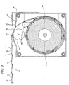
- the numeral 1 denotes in its entirety a device for protecting parts of a manufacturing machine at a zone 2 defined, for example, by two vertical walls 2a and along which there extend, for example, two guides 3 for an element 4 that moves in both directions along these guides 2.
- the protective device 1 comprises a flexible member 5 such as, for example, a belt-like element 6, having one end 6a fixed to the mobile element 4 and a second end 6b connected to a customary roller 7, illustrated in Figure 2, inside which there are elastic means for pre-loading the roller 7.
- a flexible member 5 such as, for example, a belt-like element 6, having one end 6a fixed to the mobile element 4 and a second end 6b connected to a customary roller 7, illustrated in Figure 2, inside which there are elastic means for pre-loading the roller 7.
- the belt-like element 6 is kept constantly tensioned as it rolls and unrolls onto and from the roller 7, whatever the position of the mobile element 4 along the guides 3, which are positioned horizontally in the drawings but which in practice may be in any position.
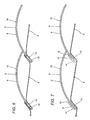
- the belt-like element 6 is connected to covering means, labelled 8 in their entirety and which, in the embodiment illustrated, consist of a plurality of cover elements 9 consisting of thin slats 10 lying transversely to the longitudinal axis 11 of the belt-like element 6 and are fixed to the latter, at a zone 12 defined by a longitudinal edge 13, through connecting means denoted generically and in their entirety by the numeral 14.
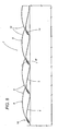
- the cover elements 9 are arranged over the belt-like element in an overlapping manner.
- the curvature radius of the slats 10 is chosen according to the radius of the roller 7 so as to minimise the space occupied by the device 1 when it is fully rolled up on the roller 7. Further, the arched shape confers rigidity on the slats 10.
- the connecting means 14 may be embodied in several ways. In Figure 4, they consist of a layer 15 of adhesive material 15 placed between the longitudinal edge 13 and the belt-like element 6. In Figure 5, the connecting means 14 comprise a strip of plastic 16 positioned along the longitudinal edge 13 of each slat 10 on the side of the edge 13 opposite the belt-like element 6. To obtain this type of connection along the edges 13 of the slats 10, there are holes 17 through which the strip 16 is fixed to the belt-like element 6 by a sealing operation.
- the connecting means 14 consist of a U-shaped fold 18 of the belt-like element 6 around the longitudinal edge 13 of each slat 10. Fixing is then accomplished by heat sealing or by the use of an adhesive.
- the connecting means 14 comprise a plastic profile 19 folded in a U shape around the longitudinal edge 13 of each slat 10.
- the fixing means may be obtained by a process of vulcanising the profile 19 on the edge 13, whilst the side of the profile 19 in contact with the belt-like element 6 is fixed to the latter by heat sealing or by interposition of a layer of adhesive material.
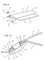
- the connecting means 14 comprise fastening means, labelled 20 in their entirety, and comprising a head 21 equipped with a stem 22 insertable into a matching hole 17 made in the edge 13 of the slat 10 and into a matching hole 23 made in the belt-like element 6 coaxially with the hole 17. It should be noticed that there may be any number of holes 23 and 17 along the edge 13.
- the free end 24 of the stem 22 protruding from the hole 17 is beaten out on the slat 10 with an interposed washer 25 with a curved surface whose concave section is opposite the respective contact zone and which, together with the beaten out end 24, forms a fastening counterhead 26.
- the head 21 and the counterhead 26 are equipped with curved surfaces 29 and 30 that define the contact zones 27 and 28 which are coaxial with the holes 17 and 23 and spaced from the edges of the latter.
- the cover elements 9 consist of a plurality of tiles 31 that overlap each other not only along the longitudinal axis 11 of the belt-like element 6, in the same way as the slats 10 of Figure 1, but also transversely to the longitudinal axis 11.
- the tiles 31 in the embodiment of Figure 11 are also arch shaped. It should be noted, however, that both the slats 10 and the tiles 31 may present a flat structure (not illustrated) and that the means 14 for connecting the tiles 31 to the belt-like element 6 may be the same as the means 14 described with reference to the slats 10.
- the cover elements 9 may be made preferably of a rigid or elastically flexible material such as plastic or metal, especially harmonic steel.
- the protective cover device 1 effectively overcomes all the drawbacks linked to different types of chippings and swarf, is extremely compact when rolled up around the roller 7, much like an ordinary belt, and guarantees a perfect protective seal.
- cleaning scraper means 32 are provided, consisting, for example, of flexible plates 33 which scrape the outside surface of the elements 9. It should be noticed that these cleaning scraper means 32 act in conjunction with respective opposing contact and support means 34 of the belt-like element 6 positioned at an opening 35 made in a container 36 that houses the roller 7.
- the opposing contact and support means 34 may consist of an arch shaped surface 37, as illustrated in Figure 2, or of one or more rollers 38 whose axes are parallel to the axis of the roller 7.
Landscapes
- Engineering & Computer Science (AREA)
- Mechanical Engineering (AREA)
- Emergency Protection Circuit Devices (AREA)
- Extrusion Moulding Of Plastics Or The Like (AREA)
- Package Frames And Binding Bands (AREA)
- Electrotherapy Devices (AREA)
- Debugging And Monitoring (AREA)
- Seal Device For Vehicle (AREA)
Claims (20)
- Un dispositif de protection pour des parties de machines de fabrication, comprenant un organe roulant flexible (5) défini par un élément de type bande (6) et des moyens couvrants (8) consistant en une pluralité d'éléments de couverture (9) fixés à l'élément de type bande (6) par l'intermédiaire de moyens d'accouplement (14) respectifs au niveau d'une zone (12) ; ledit dispositif étant caractérisé en ce que les éléments de couverture (9) sont disposés sur l'élément de type bande (6) de manière à se chevaucher et à former une structure imbriquée.
- Le dispositif selon la revendication 1, caractérisé en ce qu'il comprend un rouleau (7) autour duquel l'organe roulant flexible (5) s'enroule et se déroule et auquel les moyens couvrants (8) sont reliés.
- Le dispositif selon la revendication 1, caractérisé en ce que les éléments de couverture (9) consistent en une pluralité de lames (10) reposant transversalement à l'axe longitudinal (11) de l'élément de type bande (6) et disposées de manière à se chevaucher le long de l'axe longitudinal (11) ; les moyens d'accouplement (14) étant positionnés entre l'élément de type bande (6) et un bord longitudinal (13) respectif de chaque lame (10).
- Le dispositif selon la revendication 1, caractérisé en ce que les éléments de couverture (9) consistent en une pluralité de plaques (31) disposées de manière à se chevaucher le long de l'axe longitudinal (11) et transversalement à ce même axe longitudinal (11) ; les moyens d'accouplement (14) étant positionnés entre l'élément de type bande (6) et chaque plaque (31).
- Le dispositif selon la revendication 3 ou 4, caractérisé en ce que les lames (10) et les plaques (31) ont une structure plate.
- Le dispositif selon la revendication 3 ou 4, caractérisé en ce que les lames (10) et les plaques (31) ont une structure incurvée dont la concavité est orientée vers l'élément de type bande (6).
- Le dispositif selon l'une quelconque des revendications précédentes de 3 à 6, caractérisé en ce que les lames (10) et les plaques (31) sont réalisées dans un matériau rigide.
- Le dispositif selon l'une quelconque des revendications précédentes de 3 à 6, caractérisé en ce que les lames (10) et les plaques (31) sont réalisées dans un matériau élastiquement flexible.
- Le dispositif selon l'une quelconque des revendications précédentes de 3 à 8, caractérisé en ce que les moyens d'accouplement (14) consistent en une couche de matière adhésive (15) placée entre le bord longitudinal (13) et l'élément de type bande (6).
- Le dispositif selon l'une quelconque des revendications précédentes de 3 à 8, caractérisé en ce que les moyens d'accouplement (14) consistent en un pli en « U » (18) de l'élément de type bande (6) entourant le bord longitudinal (13) ; des moyens étant prévus pour fixer l'élément de type bande (6) au bord longitudinal (13).
- Le dispositif selon l'une quelconque des revendications précédentes de 3 à 8, caractérisé en ce que les moyens d'accouplement (14) consistent en un profilé de plastique (19) replié en « U » autour du bord longitudinal (13) ; des moyens étant prévus pour fixer un côté du profilé (19) à l'élément de type bande (6).
- Le dispositif selon l'une quelconque des revendications précédentes de 3 à 8, caractérisé en ce que les moyens d'accouplement (14) consistent en une bande de plastique (16) placée le long du bord longitudinal (13), du côté du bord (13) opposé à l'élément de type bande (6) ; des moyens étant prévus pour fixer la bande de plastique (16) à l'élément de type bande (6).
- Le dispositif selon l'une quelconque des revendications précédentes de 10 à 12, caractérisé en ce que le bord longitudinal (13) des lames (10) ou des plaques (31) comprend au moins un trou (17).
- Le dispositif selon l'une quelconque des revendications précédentes de 3 à 8 et selon la revendication 13, caractérisé en ce que les moyens d'accouplement (14) comprennent des moyens de fixation (20) pouvant être introduits dans le trou (17) pratiqué dans le bord (13) des lames (10) ou des plaques (31) ainsi que dans un trou correspondant (23) pratiqué dans l'élément de type bande (6).
- Le dispositif selon la revendication 14, caractérisé en ce que les moyens de fixation (20) comprennent une tête (21), une tige (22) et une contre-tête de blocage (26) ; la tête (21) et la contre-tête (26) présentant des surfaces courbes (29, 30) qui définissent des zones (27, 28) respectives de contact avec le bord longitudinal (13) et avec l'élément de type bande (6) ; les zones de contact (27, 28) étant essentiellement coaxiales aux trous (17, 23) et espacées des bords de ces derniers.
- Le dispositif selon la revendication 15, caractérisé en ce que la contre-tête de blocage (26) comprend une rondelle (25) ayant une surface courbe (30) dont la concavité est à l'opposé de la zone de contact (28) respective.
- Le dispositif selon l'une quelconque des revendications précédentes de 1 à 16, caractérisé en ce qu'il comprend des moyens racleurs de nettoyage (32) qui agissent en association avec les moyens couvrants (8).
- Le dispositif selon la revendication 17, caractérisé en ce que les moyens racleurs de nettoyage (32) sont placés au niveau de moyens de support et de renvoi (34) de l'élément de type bande (6).
- Le dispositif selon l'une quelconque des revendications précédentes de 3 à 18, caractérisé en ce que les lames (10) et les plaques (31) sont réalisées en matière plastique.
- Le dispositif selon l'une quelconque des revendications précédentes de 3 à 18, caractérisé en ce que les lames (10) et les plaques (31) sont réalisées dans un matériau métallique harmonique.
Applications Claiming Priority (3)
| Application Number | Priority Date | Filing Date | Title |
|---|---|---|---|
| ITBO20030070 | 2003-02-19 | ||
| IT000070A ITBO20030070A1 (it) | 2003-02-19 | 2003-02-19 | Dispositivo di protezione. |
| PCT/IB2004/000451 WO2004073921A1 (fr) | 2003-02-19 | 2004-02-13 | Dispositif de protection |
Publications (2)
| Publication Number | Publication Date |
|---|---|
| EP1594652A1 EP1594652A1 (fr) | 2005-11-16 |
| EP1594652B1 true EP1594652B1 (fr) | 2006-09-27 |
Family
ID=32894136
Family Applications (1)
| Application Number | Title | Priority Date | Filing Date |
|---|---|---|---|
| EP04710949A Expired - Lifetime EP1594652B1 (fr) | 2003-02-19 | 2004-02-13 | Dispositif de protection |
Country Status (5)
| Country | Link |
|---|---|
| EP (1) | EP1594652B1 (fr) |
| AT (1) | ATE340673T1 (fr) |
| DE (1) | DE602004002566T2 (fr) |
| IT (1) | ITBO20030070A1 (fr) |
| WO (1) | WO2004073921A1 (fr) |
Families Citing this family (1)
| Publication number | Priority date | Publication date | Assignee | Title |
|---|---|---|---|---|
| DE202005014233U1 (de) * | 2005-09-08 | 2005-11-10 | Arno Arnold Gmbh | Gliederschürzeneinrichtung |
Family Cites Families (3)
| Publication number | Priority date | Publication date | Assignee | Title |
|---|---|---|---|---|
| DE3533767C2 (de) * | 1985-09-21 | 1994-04-21 | Schuler Gmbh L | Einrichtung zur Abdeckung eines Unterflurschachtes im Bewegungsbereich eines Schiebetisches einer Presse |
| US5067285A (en) * | 1990-04-16 | 1991-11-26 | Progressive Blasting Systems, Inc. | Seal belt assembly for compartments in which blasting, spraying and the like operations are performed |
| US5624363A (en) * | 1995-02-09 | 1997-04-29 | Brother Kogyo Kabushiki Kaisha | Machine tool having a protective cover |
-
2003
- 2003-02-19 IT IT000070A patent/ITBO20030070A1/it unknown
-
2004
- 2004-02-13 WO PCT/IB2004/000451 patent/WO2004073921A1/fr not_active Ceased
- 2004-02-13 EP EP04710949A patent/EP1594652B1/fr not_active Expired - Lifetime
- 2004-02-13 DE DE602004002566T patent/DE602004002566T2/de not_active Expired - Fee Related
- 2004-02-13 AT AT04710949T patent/ATE340673T1/de not_active IP Right Cessation
Also Published As
| Publication number | Publication date |
|---|---|
| ITBO20030070A1 (it) | 2004-08-20 |
| WO2004073921A1 (fr) | 2004-09-02 |
| DE602004002566T2 (de) | 2007-06-21 |
| DE602004002566D1 (de) | 2006-11-09 |
| ATE340673T1 (de) | 2006-10-15 |
| EP1594652A1 (fr) | 2005-11-16 |
Similar Documents
| Publication | Publication Date | Title |
|---|---|---|
| US4344474A (en) | Insulated shade | |
| JP3444672B2 (ja) | 窓遮閉体 | |
| EP2404021B1 (fr) | Porte lavable | |
| CA2936524C (fr) | Porte a enroulement rapide comprenant un rideau presentant des bords elastiques | |
| EP3460164B1 (fr) | Panneaux de porte isolés | |
| EP1216339B1 (fr) | Systeme d'etancheite pour unite de vitrage isolant | |
| CA2021789C (fr) | Store a enroulement, pour portes, fenetres et autres ouvertures similaires | |
| EP0279798B1 (fr) | Tôle profilée pour la construction | |
| US4694952A (en) | Scraper cleaning apparatus for reversible conveyor belts | |
| HU214489B (hu) | Deformálható lemezanyag főleg tetőablakok takarólemezéhez, valamint eljárás ilyen lemezanyag gyártására | |
| AU780303B2 (en) | Hanging for a roller blind with lateral guidance | |
| DK2152982T3 (en) | Fan band, especially for steep take | |
| AU2003292114B2 (en) | Planar metal element and profile element | |
| ES2311629T3 (es) | Fuelle con paneles moldeados. | |
| US20080202707A1 (en) | Roll-up protective device for slideways of elements of machines or systems | |
| CZ69894A3 (en) | Roof panel-like bordering lead-free material | |
| EP1594652A1 (fr) | Dispositif de protection | |
| LT4090B (en) | Ventilation strip | |
| EP0004455A2 (fr) | Rideau pouvant être replié ou déployé de manière sélective ainsi que méthode pour sa fabrication | |
| EP0065876A2 (fr) | Système d'étanchéité pour isolations mobiles | |
| US3842560A (en) | Industrial building construction | |
| US4241539A (en) | Seal for sides of pivoted blade structures | |
| EP1842980A2 (fr) | Protection anti-goutte pour bâches | |
| US6591888B2 (en) | Covering and protecting device for machinery | |
| PL183888B1 (pl) | Urządzenie do reprofilowania materiałów pofałdowanych |
Legal Events
| Date | Code | Title | Description |
|---|---|---|---|
| PUAI | Public reference made under article 153(3) epc to a published international application that has entered the european phase |
Free format text: ORIGINAL CODE: 0009012 |
|
| 17P | Request for examination filed |
Effective date: 20050804 |
|
| AK | Designated contracting states |
Kind code of ref document: A1 Designated state(s): AT BE BG CH CY CZ DE DK EE ES FI FR GB GR HU IE IT LI LU MC NL PT RO SE SI SK TR |
|
| AX | Request for extension of the european patent |
Extension state: AL LT LV MK |
|
| GRAP | Despatch of communication of intention to grant a patent |
Free format text: ORIGINAL CODE: EPIDOSNIGR1 |
|
| DAX | Request for extension of the european patent (deleted) | ||
| GRAS | Grant fee paid |
Free format text: ORIGINAL CODE: EPIDOSNIGR3 |
|
| GRAA | (expected) grant |
Free format text: ORIGINAL CODE: 0009210 |
|
| AK | Designated contracting states |
Kind code of ref document: B1 Designated state(s): AT BE BG CH CY CZ DE DK EE ES FI FR GB GR HU IE IT LI LU MC NL PT RO SE SI SK TR |
|
| PG25 | Lapsed in a contracting state [announced via postgrant information from national office to epo] |
Ref country code: IT Free format text: LAPSE BECAUSE OF FAILURE TO SUBMIT A TRANSLATION OF THE DESCRIPTION OR TO PAY THE FEE WITHIN THE PRESCRIBED TIME-LIMIT;WARNING: LAPSES OF ITALIAN PATENTS WITH EFFECTIVE DATE BEFORE 2007 MAY HAVE OCCURRED AT ANY TIME BEFORE 2007. THE CORRECT EFFECTIVE DATE MAY BE DIFFERENT FROM THE ONE RECORDED. Effective date: 20060927 Ref country code: FI Free format text: LAPSE BECAUSE OF FAILURE TO SUBMIT A TRANSLATION OF THE DESCRIPTION OR TO PAY THE FEE WITHIN THE PRESCRIBED TIME-LIMIT Effective date: 20060927 Ref country code: BE Free format text: LAPSE BECAUSE OF FAILURE TO SUBMIT A TRANSLATION OF THE DESCRIPTION OR TO PAY THE FEE WITHIN THE PRESCRIBED TIME-LIMIT Effective date: 20060927 Ref country code: AT Free format text: LAPSE BECAUSE OF FAILURE TO SUBMIT A TRANSLATION OF THE DESCRIPTION OR TO PAY THE FEE WITHIN THE PRESCRIBED TIME-LIMIT Effective date: 20060927 Ref country code: LI Free format text: LAPSE BECAUSE OF FAILURE TO SUBMIT A TRANSLATION OF THE DESCRIPTION OR TO PAY THE FEE WITHIN THE PRESCRIBED TIME-LIMIT Effective date: 20060927 Ref country code: CZ Free format text: LAPSE BECAUSE OF FAILURE TO SUBMIT A TRANSLATION OF THE DESCRIPTION OR TO PAY THE FEE WITHIN THE PRESCRIBED TIME-LIMIT Effective date: 20060927 Ref country code: NL Free format text: LAPSE BECAUSE OF FAILURE TO SUBMIT A TRANSLATION OF THE DESCRIPTION OR TO PAY THE FEE WITHIN THE PRESCRIBED TIME-LIMIT Effective date: 20060927 Ref country code: SI Free format text: LAPSE BECAUSE OF FAILURE TO SUBMIT A TRANSLATION OF THE DESCRIPTION OR TO PAY THE FEE WITHIN THE PRESCRIBED TIME-LIMIT Effective date: 20060927 Ref country code: RO Free format text: LAPSE BECAUSE OF FAILURE TO SUBMIT A TRANSLATION OF THE DESCRIPTION OR TO PAY THE FEE WITHIN THE PRESCRIBED TIME-LIMIT Effective date: 20060927 Ref country code: CH Free format text: LAPSE BECAUSE OF FAILURE TO SUBMIT A TRANSLATION OF THE DESCRIPTION OR TO PAY THE FEE WITHIN THE PRESCRIBED TIME-LIMIT Effective date: 20060927 Ref country code: SK Free format text: LAPSE BECAUSE OF FAILURE TO SUBMIT A TRANSLATION OF THE DESCRIPTION OR TO PAY THE FEE WITHIN THE PRESCRIBED TIME-LIMIT Effective date: 20060927 |
|
| REG | Reference to a national code |
Ref country code: GB Ref legal event code: FG4D |
|
| REG | Reference to a national code |
Ref country code: CH Ref legal event code: EP |
|
| REG | Reference to a national code |
Ref country code: IE Ref legal event code: FG4D |
|
| REF | Corresponds to: |
Ref document number: 602004002566 Country of ref document: DE Date of ref document: 20061109 Kind code of ref document: P |
|
| PG25 | Lapsed in a contracting state [announced via postgrant information from national office to epo] |
Ref country code: SE Free format text: LAPSE BECAUSE OF FAILURE TO SUBMIT A TRANSLATION OF THE DESCRIPTION OR TO PAY THE FEE WITHIN THE PRESCRIBED TIME-LIMIT Effective date: 20061227 Ref country code: BG Free format text: LAPSE BECAUSE OF FAILURE TO SUBMIT A TRANSLATION OF THE DESCRIPTION OR TO PAY THE FEE WITHIN THE PRESCRIBED TIME-LIMIT Effective date: 20061227 Ref country code: DK Free format text: LAPSE BECAUSE OF FAILURE TO SUBMIT A TRANSLATION OF THE DESCRIPTION OR TO PAY THE FEE WITHIN THE PRESCRIBED TIME-LIMIT Effective date: 20061227 |
|
| PG25 | Lapsed in a contracting state [announced via postgrant information from national office to epo] |
Ref country code: ES Free format text: LAPSE BECAUSE OF FAILURE TO SUBMIT A TRANSLATION OF THE DESCRIPTION OR TO PAY THE FEE WITHIN THE PRESCRIBED TIME-LIMIT Effective date: 20070107 |
|
| PG25 | Lapsed in a contracting state [announced via postgrant information from national office to epo] |
Ref country code: MC Free format text: LAPSE BECAUSE OF NON-PAYMENT OF DUE FEES Effective date: 20070228 |
|
| NLV1 | Nl: lapsed or annulled due to failure to fulfill the requirements of art. 29p and 29m of the patents act | ||
| PG25 | Lapsed in a contracting state [announced via postgrant information from national office to epo] |
Ref country code: PT Free format text: LAPSE BECAUSE OF FAILURE TO SUBMIT A TRANSLATION OF THE DESCRIPTION OR TO PAY THE FEE WITHIN THE PRESCRIBED TIME-LIMIT Effective date: 20070313 |
|
| REG | Reference to a national code |
Ref country code: CH Ref legal event code: PL |
|
| EN | Fr: translation not filed | ||
| PLBE | No opposition filed within time limit |
Free format text: ORIGINAL CODE: 0009261 |
|
| STAA | Information on the status of an ep patent application or granted ep patent |
Free format text: STATUS: NO OPPOSITION FILED WITHIN TIME LIMIT |
|
| 26N | No opposition filed |
Effective date: 20070628 |
|
| PG25 | Lapsed in a contracting state [announced via postgrant information from national office to epo] |
Ref country code: IE Free format text: LAPSE BECAUSE OF NON-PAYMENT OF DUE FEES Effective date: 20070213 |
|
| PG25 | Lapsed in a contracting state [announced via postgrant information from national office to epo] |
Ref country code: FR Free format text: LAPSE BECAUSE OF FAILURE TO SUBMIT A TRANSLATION OF THE DESCRIPTION OR TO PAY THE FEE WITHIN THE PRESCRIBED TIME-LIMIT Effective date: 20070525 Ref country code: GR Free format text: LAPSE BECAUSE OF FAILURE TO SUBMIT A TRANSLATION OF THE DESCRIPTION OR TO PAY THE FEE WITHIN THE PRESCRIBED TIME-LIMIT Effective date: 20061228 |
|
| PG25 | Lapsed in a contracting state [announced via postgrant information from national office to epo] |
Ref country code: EE Free format text: LAPSE BECAUSE OF FAILURE TO SUBMIT A TRANSLATION OF THE DESCRIPTION OR TO PAY THE FEE WITHIN THE PRESCRIBED TIME-LIMIT Effective date: 20060927 |
|
| GBPC | Gb: european patent ceased through non-payment of renewal fee |
Effective date: 20080213 |
|
| PG25 | Lapsed in a contracting state [announced via postgrant information from national office to epo] |
Ref country code: FR Free format text: LAPSE BECAUSE OF FAILURE TO SUBMIT A TRANSLATION OF THE DESCRIPTION OR TO PAY THE FEE WITHIN THE PRESCRIBED TIME-LIMIT Effective date: 20060927 |
|
| PGFP | Annual fee paid to national office [announced via postgrant information from national office to epo] |
Ref country code: DE Payment date: 20090206 Year of fee payment: 6 |
|
| PG25 | Lapsed in a contracting state [announced via postgrant information from national office to epo] |
Ref country code: GB Free format text: LAPSE BECAUSE OF NON-PAYMENT OF DUE FEES Effective date: 20080213 |
|
| PG25 | Lapsed in a contracting state [announced via postgrant information from national office to epo] |
Ref country code: CY Free format text: LAPSE BECAUSE OF FAILURE TO SUBMIT A TRANSLATION OF THE DESCRIPTION OR TO PAY THE FEE WITHIN THE PRESCRIBED TIME-LIMIT Effective date: 20060927 Ref country code: LU Free format text: LAPSE BECAUSE OF NON-PAYMENT OF DUE FEES Effective date: 20070213 |
|
| PGFP | Annual fee paid to national office [announced via postgrant information from national office to epo] |
Ref country code: IT Payment date: 20090226 Year of fee payment: 6 |
|
| PG25 | Lapsed in a contracting state [announced via postgrant information from national office to epo] |
Ref country code: TR Free format text: LAPSE BECAUSE OF FAILURE TO SUBMIT A TRANSLATION OF THE DESCRIPTION OR TO PAY THE FEE WITHIN THE PRESCRIBED TIME-LIMIT Effective date: 20060927 Ref country code: HU Free format text: LAPSE BECAUSE OF FAILURE TO SUBMIT A TRANSLATION OF THE DESCRIPTION OR TO PAY THE FEE WITHIN THE PRESCRIBED TIME-LIMIT Effective date: 20070328 |
|
| PG25 | Lapsed in a contracting state [announced via postgrant information from national office to epo] |
Ref country code: DE Free format text: LAPSE BECAUSE OF NON-PAYMENT OF DUE FEES Effective date: 20100901 |
|
| PG25 | Lapsed in a contracting state [announced via postgrant information from national office to epo] |
Ref country code: IT Free format text: LAPSE BECAUSE OF NON-PAYMENT OF DUE FEES Effective date: 20100213 |