EP1594023A2 - Method for automatic configuration of a process control system and corresponding process control system - Google Patents
Method for automatic configuration of a process control system and corresponding process control system Download PDFInfo
- Publication number
- EP1594023A2 EP1594023A2 EP05009601A EP05009601A EP1594023A2 EP 1594023 A2 EP1594023 A2 EP 1594023A2 EP 05009601 A EP05009601 A EP 05009601A EP 05009601 A EP05009601 A EP 05009601A EP 1594023 A2 EP1594023 A2 EP 1594023A2
- Authority
- EP
- European Patent Office
- Prior art keywords
- slave
- master
- process control
- control system
- bus system
- Prior art date
- Legal status (The legal status is an assumption and is not a legal conclusion. Google has not performed a legal analysis and makes no representation as to the accuracy of the status listed.)
- Granted
Links
Images


Classifications
-
- G—PHYSICS
- G05—CONTROLLING; REGULATING
- G05B—CONTROL OR REGULATING SYSTEMS IN GENERAL; FUNCTIONAL ELEMENTS OF SUCH SYSTEMS; MONITORING OR TESTING ARRANGEMENTS FOR SUCH SYSTEMS OR ELEMENTS
- G05B19/00—Program-control systems
- G05B19/02—Program-control systems electric
- G05B19/04—Program control other than numerical control, i.e. in sequence controllers or logic controllers
- G05B19/042—Program control other than numerical control, i.e. in sequence controllers or logic controllers using digital processors
-
- G—PHYSICS
- G06—COMPUTING OR CALCULATING; COUNTING
- G06F—ELECTRIC DIGITAL DATA PROCESSING
- G06F13/00—Interconnection of, or transfer of information or other signals between, memories, input/output devices or central processing units
- G06F13/38—Information transfer, e.g. on bus
- G06F13/42—Bus transfer protocol, e.g. handshake; Synchronisation
- G06F13/4204—Bus transfer protocol, e.g. handshake; Synchronisation on a parallel bus
- G06F13/4208—Bus transfer protocol, e.g. handshake; Synchronisation on a parallel bus being a system bus, e.g. VME bus, Futurebus, Multibus
-
- G—PHYSICS
- G05—CONTROLLING; REGULATING
- G05B—CONTROL OR REGULATING SYSTEMS IN GENERAL; FUNCTIONAL ELEMENTS OF SUCH SYSTEMS; MONITORING OR TESTING ARRANGEMENTS FOR SUCH SYSTEMS OR ELEMENTS
- G05B2219/00—Program-control systems
- G05B2219/20—Pc systems
- G05B2219/22—Pc multi processor system
- G05B2219/2228—Leader detects and configures followers
-
- G—PHYSICS
- G05—CONTROLLING; REGULATING
- G05B—CONTROL OR REGULATING SYSTEMS IN GENERAL; FUNCTIONAL ELEMENTS OF SUCH SYSTEMS; MONITORING OR TESTING ARRANGEMENTS FOR SUCH SYSTEMS OR ELEMENTS
- G05B2219/00—Program-control systems
- G05B2219/20—Pc systems
- G05B2219/25—Pc structure of the system
- G05B2219/25296—Identification module, type connected I-O, device
Definitions
- the present invention relates to a method for automatic configuration of a process control system and a process control system adapted to carry out the method.
- process control systems With respect to measurement and control technology, and also with respect to process control systems, frequently sensors have to be connected to a control unit or to an analyzing system. Besides the physical connection of the components involved, usually also it is required to adapt the apparatus configuration of the processing system, i.e. the control unit, to the origin of the input data, i.e. the sensors.
- the arrangement of process control systems can basically be described as follows: on one hand, there is a field apparatus. This can for example be a sensor like a pressure measuring transducer, a level switch, a flow meter, and so on. Or this can also be an actuator like a valve, a slide valve, and so on.
- the senor provides measurement values via a bus system to the control unit, whereby respective measurement values have a different relevance according to the measuring method used.
- pressure sensors provide for example measurement values which are calibrated in pressure units as bar, Pascal or mmH 2 O
- distance measuring sensors provide values, being calibrated in m, mm, or ft.
- Flow rates are usually measured by the systems in 1/s, m 3 /h, or cftps, and so on.
- control units being termed as analyzing systems in the following.
- the control units typically are connected to a field apparatus via the above mentioned bus system.
- the task of analyzing systems is based on reading the input measurement values (of the field apparatus), to process them adequately, and then generate output control signals (switching signals, current signals, digital values, and so on) from the derived results.
- Configuration of the analyzing system typically results via an input unit (keys and display) on the apparatus side, however, it can also result via a configuration interface by means of a PC.
- the processed data can also be transmitted via bus systems through gateways or further process control systems.
- Each software block represents a black box.
- the black box comprises inputs for receiving input signals, and outputs for providing the processed signals.
- These software blocks respectively represent an object, classifying associated tasks such that the respective result values can be used as virtually calibrated for arbitrary subsequent blocks.
- Typical functions can be:
- Function components provide their resulting values for use in output components.
- a plurality of measurement loop can be processed. Therefore, if a control is connected to a plurality of field apparatuses via a bus system, then, by adequate configuring of the control unit, a corresponding set of measurement loops can be composed in the control unit from the pool of components.
- the configuration either results from an operating desk connected to the control or alternatively via a configuration computer via a bus connection. By this procedure, it is necessary for a user operating the system, to not only take account of the installation of the apparatus and its wiring, but rather to also carry out complicated configurations at the apparatus.
- control should be able to identify a sensor connected to its output and matching to a certain sensor profile, and then automatically set up the corresponding measurement loop profile. An immediately functioning measurement can be thus provided.
- this process should be applicable via different bus systems (as HART, Profibus, Fieldbus Foundation, and so on), containing the necessary information for the sensors in form of parameters via the respective bus per definition.
- Implementations of the invention can include one or more of the following features.
- a method for automatic configuration of a process control system comprising a master and at least one slave, whereby the master controls the at least one slave, which is connected to and communicates with the master via a bus system, and processes data received from the at least one slave, whereby the master automatically identifies the at least one slave via the bus system, and subsequently automatically generates an apparatus configuration for setting up the slave according to its identification such that the slave is ready to be operated in the process control system.
- the master is an analyzing apparatus, in particular a control unit, comprising allocation tables, from which the master selects the adequate apparatus configuration for the slave identified.
- the slave is a field apparatus, in particular a sensor or an actuator.
- the identification of the connected slave is carried out by means of the functionality of the master.
- communication towards the bus system is initiated by the master.
- Yet another aspect of the invention is that for identifying the field apparatus, the master retrieves information concerning manufacturer, type, apparatus TAG by means of standardized commands. The master compares the identification data of the slave to apparatus profiles, contained in the allocation tables, to find the adequate apparatus profile to set up the slave for operation in the process control system.
- the master generates a measurement loop comprising an input component, an output component, and a function component for the apparatus configuration.
- the allocation table can also be supplemented by reloadable adapted apparatus profiles.
- the automatically generated measurement loops are corrected interactively. During the correction of the measurement loops, the automatic generation of measurement loops is deactivated until new slaves are connected to the master or until the automatic measurement loop generation is reactivated.
- the automatic adaptation of already present measurement loops is carried out when an already connected slave is replaced by another type of slave.
- a method for automatic configuration of a process control system comprising at least one field apparatus, which is connected via a bus system to an analyzing apparatus, whereby upon starting the analyzing apparatus, the latter verifies the presence of the field apparatus at the bus system at a certain bus address, and, upon response of the bus system, for identification of the field apparatus, requests information concerning manufacturer, type, and apparatus TAG of the field apparatus via the bus system, and subsequent to the identification, the analyzing system compares data retrieved during the identification process to field apparatus profiles stored in allocation tables of the analyzing apparatus, and, upon an coincidence, generates an apparatus configuration in form of a measurement loop, comprising an input component, a function component, and an output component, by means of which the field apparatus is ready for operation.
- a further aspect of the present invention is a process control system, comprising a master and at least one slave, whereby the master is adapted to control the slave and to process data received from the slave, and the slave is adapted to be connected to and to communicate with the master via a bus system, whereby the master is adapted to automatically identify the slave via the bus system, and to subsequently generate an apparatus configuration for setting up the slave according to its identification such that the slave is ready to be operated in the process control system.
- the master is an analyzing apparatus and the slave is a field apparatus according to an aspect of the invention.
- the master is a control unit and the slave is a sensor or an actuator.
- the master comprises allocation tables, which contain a number of predefined apparatus configurations suitable for a number of the field apparatuses.
- the allocation tables are supplementable via an input device.
- the bus system is a HART-bus system according to a further aspect of the invention.
- the bus system comprises commands for the master for requesting the presence of a slave at the bus system.
- the allocation tables are supplementable by reloadable adapted apparatus profiles.
- the master is adapted to generate a measurement loop for a specific identified slave.
- the measurement loop comprises at least one input component, at least one output component, and at least one function component.
- allocation tables comprise fixed measurement loop profiles for each apparatus profile.
- Fig. 1 is a schematic diagram of a process control system.
- a control unit 4 is connected via a bus system 5 to two sensors 14 and an actuator 15.
- a PC 10 is connected to the control unit 4 via a configuration interface 3.
- the configuration of the process control system 1 results by means of an operating desk (e.g. a keyboard and a display).
- Fig. 2 is another schematic diagram of a further arrangement of a process control system.
- a gateway 16 is connected between the control unit 4 and the PC 10.
- the processed data can be transferred to gateways 16 or to other process control systems.
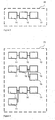
- Fig. 3 shows a measurement loop 23, comprising an input component or input block 11, a function component or function block 12, and an output component or output block 13.
- the function component 12 receives data directly form input component 11, and output component 13 in turn receives data from function component 12.
- Fig. 4 shows a control unit comprising several measurement loops. In case, the control unit 4 is connected to a plurality of field apparatuses 14 via the bus system 5, by adequate configuring of the control unit 4, a set of measurement loops 23 can be composed from a pool of components.
- a system comprising a plurality of sensors 14, connected via a bus system 5 to the control unit 4.
- the control unit in turn is connected to a PC 10.
- the control unit 4 comprises a number of input components 11, function components 12, output components 13, and message components 15. All components, in the delivery state, are unconfigured, that means without any relation with respect to each other.
- the process control system comprises the control unit 4 as master of the system and a couple of sensors as slaves of the system, connected thereto over a bus system 5,
- a PC 10 is connected to the control unit 4.
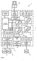
- the components, namely input components 11, function components 12, and output components 13 for establishing a measurement loop 23 are still in the unconfigured state.
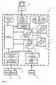
- the control unit 4 comprises the allocation tables 42, comprising sensor profiles and type of measurement loop fitting thereto.
- HART sensors are used having certain characteristics, these can be verified at HART input terminals; otherwise used PA sensors can e.g. be verified at Profibus inputs and so on.
- HART sensors instead of smart sensors, pure 4 - 20 mA sensors can also be identified. This assumption is made, if the connection of a sensor is detected (by means of current consumption within certain limits), but, however, no reaction to the digital signal results.
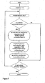
- the identification of the connected sensor is carried out by means of the functionality 41, the data flow of which is shown in Fig. 7 in principle.
- the automatic measurement loop operation is started. That means that the control unit 4 automatically takes up communication towards the bus system 5.
- the control unit requests - as master of the system - by means of "trial and error" - to a certain bus address, whether a slave 14, 15 is connected to the bus system 5 or not.
- bus systems provide special commands (e.g. according to HART, Universal Commands are used).
- the analyzing apparatus receives a response after such a trial, then information with respect to manufacturer and type of apparatus is selectively inquired. This information can also be requested by means of standardized commands with respect to the already mentioned bus systems (excerpt of the definitions, see tables 1 - 3).
- the slaves provide information over fixedly defined commands for the stored apparatus TAG. According to information received concerning the type of apparatus, an advanced analysis for the sensor connected thereto can be carried out. Thus, for example it can be determined, in which measurement range and according to which physical measurement category the sensor is operated.
- control unit i.e. the analyzing apparatus
- the control unit carries out a comparison of the input data with sensor profiles fixedly stored in the control unit 4 in allocation tables 42.
- the control automatically generates adequate measurement loop configurations. It also generates a complete measurement loop 23 according to Fig. 5, consisting of an appropriate input component 11, a function component 12, and an output component 13.
- the control unit 4 receives a response under HART address 2 from a slave 14 (see Fig. 7).
- the further communication procedures provide data from the example shown above.
- Fig. 8 it can be seen that the analyzing apparatus generates an input component for distance measurement and generates the measuring principle RADAR for HART address 2.
- control unit generates a function component for level measurement comprising the calibration unit "meter” (see Fig. 9). According to a known measurement range, the latter is automatically entered into the function component as calibration range (see Fig. 10).
- the control unit selects for this purpose the output component type most frequently required, namely a switching output, configured for the switching function "overfill protection" (Fig. 11).
- the user When starting the process control system, the user receives - without any further assistance - an adequate measurement loop for the sensor connected, comprising an input component, a function component, and an output component, rendering the system ready to be operated.
- the allocation table 42 can also be adapted to be supplementable by reloadable profiles. According to this, the allocation table contains two types of data set entries:
- automatically generated measurement loop profiles can be interactively corrected by the user.
- the automatic generation of measurement units 23 is deactivated until either new slaves (having different identification characteristics) are connected to the control unit / analyzing apparatus, or the control unit is reactivated by means of a function defined for this purpose (for example a reset key or a function initiated by software) for carrying out the automatic measurement loop generation.
- the invention can be applied to simple one-channel analyzing systems as well as to complex systems.
Landscapes
- Engineering & Computer Science (AREA)
- Physics & Mathematics (AREA)
- General Physics & Mathematics (AREA)
- Theoretical Computer Science (AREA)
- Automation & Control Theory (AREA)
- General Engineering & Computer Science (AREA)
- Testing And Monitoring For Control Systems (AREA)
- Control By Computers (AREA)
- Programmable Controllers (AREA)
Abstract
Description
- Input blocks or input components, respectively,
comprising the set of information with respect to a connected field apparatus (address command, type of apparatus, input values). The input components receive their measurement values from the bus interface (possibly a communication component), and usually transmit them without any change to function components. - Function components or function blocks, respectively,
function components receive their input data, e.g. directly, from input components. During the processing of field apparatus input data, it has to be considered that for a further processing of e.g. pressure measurement values, other rules and functions are reasonable than they are for further processing of distance or flow values.
- "difference measurement",
- "measurement in a pressurized container",
- "continous interface measurement, and
- "averaging".
- Output components or output blocks
output components receive their input data directly from function components. They serve for controlling and generating, of output signals, respectively (switching signals, current-voltage output or digital information).
- Fig. 1
- is a schematic diagram of an arrangement of a process control system.
- Fig. 2
- is a schematic diagram of another arrangement of a process control system.
- Fig. 3
- is a schematic diagram, showing a measurement loop block.
- Fig. 4
- is another schematic diagram, showing an arrangement of several measurement loop blocks.
- Fig. 5
- is a schematic diagram of a process control system according to the invention.
- Fig. 6
- is a further schematic diagram of the process control system according to the invention.
- Fig. 7
- is a flow chart of the inventive method.
- Fig. 8
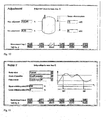
- is a screenshot of a window for allocation of an input to a measurement loop.
- Fig. 9
- is a screenshot of a window for the basic setting for a measurement loop.
- Fig. 10
- is a screenshot of a window for allocation of percentage values to sensor input data.
- Fig. 11
- is a screenshot of a window for settings for a relais.
Fig. 4 shows a control unit comprising several measurement loops. In case, the
| Examples for manufacturer IDs | ||
| Identifier | Value | Meaning |
| Manufacturer ID | 98 | Manufacturer: |
| Manufacturer ID | ||
| 42 | Manufacturer: Siemens | |
| Manufacturer ID | 17 | Manufacturer: E+H |
| Device Type Codes HART-Sensors Series 60 | ||
| Type | Apparatus designation | Device type code (HART) |
| PULS | VEGAPULS | 232/0xE8 |
| FLEX | VEGAFLEX | 231/0xE7 |
| SON | VEGASON | 230/0xE6 |
| SWING | VEGASWING | 229/0xE5 |
| VIB | VEGAVIB | 228/0xE4 |
| CAP | VEGACAP | 227/0xE3 |
| BAR | VEGABAR | 226/0xE2 |
| DIF | VEGADIF | 225/0xE1 |
| Device Type Codes Profibus-Sensors Series 60 | |||
| Apparatus | |||
| VEGA | Profile | ||
| 3 | |||
| SON | VEGASON | 0x0770 | 0x9701 |
| FLEX | VEGAFLEX | 0x0771 | 0x9700 |
| PULS | VEGAPULS | 0x0772 | 0x9700 |
| CAP | VEGACAP | 0x076E | 0x9700 |
| BAR | VEGABAR | 0x076F | 0x9701 |
| Excerpt of the allocation instruction for input components | ||
| Input component initialization | ||
| Sensor profile | Input value | HART address |
| Son | Distance | Appropriate for slave |
| Puls | Distance | Appropriate for slave |
| Flex | Distance | Appropriate for slave |
| Bar | Pressure | Appropriate for slave |
| HART Generic | PV | Appropriate for slave |
| 4 - 20 mA | Current | - |
| Excerpt of the allocation instruction for function components | |||
| Function component initialization | |||
| Sensor profile | measurement loop tag | Application | Calibration unit |
| Son | Device TAG | Level | m |
| Puls | Device TAG | Level | m |
| Flex | Device TAG | Level | m |
| Bar | Device TAG | Level | bar |
Claims (24)
- A method for automatic configuration of a process control system (1) comprising a master and at least one slave,
whereby the master controls the at least one slave, which is connected to and communicates with the master via a bus system (5), and processes data received from the at least one slave,
whereby the master automatically identifies the at least one slave via the bus system (5), and subsequently automatically generates an apparatus configuration for setting up the slave according to its identification such that the slave is ready to be operated in the process control system (1). - The method according to claim 1, whereby the master is an analyzing apparatus, in particular a control unit (4), comprising allocation tables, from which it selects the adequate apparatus configuration for the slave identified.
- The method according to claim 1 or 2, whereby the slave is a field apparatus, in particular a sensor (14) or an actuator (15).
- The method according to any of claims 1 to 3, whereby the identification of the connected slave is carried out by means of the functionality (41) of the master.
- The method according to any of claims 1 to 4, whereby upon starting the process control system (1), communication towards the bus system (5) is initiated by the master.
- The method according to any of claims 1 to 5, whereby for identifying the field apparatus, the master retrieves information concerning manufacturer, type, apparatus TAG by means of standardized commands.
- The method according to any of claims 1 to 6, whereby the master compares the identification data of the slave to apparatus profiles, contained in the allocation tables, to find the adequate apparatus profile to set up the slave for operation in the process control system (1).
- The method according to any of claims 1 to 7, whereby the master generates a measurement loop (23) comprising an input component (11), an output component (13), and a function component (12) for the apparatus configuration.
- The method according to any of claims 1 to 8, whereby the allocation table is supplemented by reloadable adapted apparatus profiles.
- The method according to claim 8 or 9, whereby automatically generated measurement loop (23) are corrected interactively.
- The method according to any of claims 8 to 10, whereby during the correction of the measurement loop (23), the automatic generation of measurement loop (23) is deactivated until new slaves are connected to the master or until the automatic measurement loop generation is reactivated.
- The method according to any of claims 1 to 11, whereby the automatic adaptation of already present measurement loop (23) is carried out when an already connected slave is replaced by another type of slave.
- A method for automatic configuration of a process control system (1), comprising at least one field apparatus, which is connected via a bus system to an analyzing apparatus, whereby
upon starting the analyzing apparatus, the latter verifies the presence of the field apparatus at the bus system (5) at a certain bus address, and
upon response of the bus system (5), for identification of the field apparatus, requests information concerning manufacturer, type, and apparatus TAG of the field apparatus via the bus system (5), and
subsequent to the identification, the analyzing system compares data retrieved during the identification process to field apparatus profiles stored in allocation tables of the analyzing apparatus, and
upon an coincidence, generates an apparatus configuration in form of a measurement loop (23), comprising an input component (11), a function component (12), and an output component (13), by means of which the field apparatus is ready for operation. - A process control system (1) comprising
a master, and
at least one slave,
whereby the master is adapted to control the slave and to process data received from the slave,
whereby the slave is adapted to be connected to and to communicate with the master via a bus system (5),
whereby the master is adapted to automatically identify the slave via the bus system (5), and to subsequently, generate an apparatus configuration for setting up the slave according to its identification such that the slave is ready to be operated in the process control system (1). - The process control system (1) according to claim 14, whereby the master is an analyzing apparatus and the slave is a field apparatus.
- The process control system (1) according to claim 14 or 16, whereby the master is a control unit (4) and the slave is a sensor (14) or an actuator (15).
- The process control system (1) according to any of claims 14 to 16, whereby the master comprises allocation tables, which contain a number of predefined apparatus configurations suitable for a number of the field apparatuses.
- The process control system (1) according to claim 17, whereby the allocation tables are supplementable via an input device (10).
- The process control system (1) according to any of claims 14 to 18, whereby the bus system (5) is a HART-bus system.
- The process control system (1) according to any of claims 14 to 19, whereby the bus system (5) comprises commands for the master for requesting the presence of a slave at the bus system (5).
- The process control system (1) according to any of claims 17 to 20, whereby the allocation tables are supplementable by reloadable adapted apparatus profiles.
- The process control system (1) according to any of claims 14 to 21, whereby the master is adapted to generate a measurement loop (23) for a specific identified slave.
- The process control system (1) according to claim 22, whereby the measurement loop (23) comprises at least one input component (11), at least one output component (13), and at least one function component (12).
- The process control system (1) according to any of claims 17 to 23, whereby the allocation tables comprise fixed measurement loop profiles for each apparatus profile.
Applications Claiming Priority (2)
| Application Number | Priority Date | Filing Date | Title |
|---|---|---|---|
| US56820304P | 2004-05-05 | 2004-05-05 | |
| US568203P | 2004-05-05 |
Publications (3)
| Publication Number | Publication Date |
|---|---|
| EP1594023A2 true EP1594023A2 (en) | 2005-11-09 |
| EP1594023A3 EP1594023A3 (en) | 2006-01-11 |
| EP1594023B1 EP1594023B1 (en) | 2007-09-26 |
Family
ID=34936044
Family Applications (1)
| Application Number | Title | Priority Date | Filing Date |
|---|---|---|---|
| EP05009601A Ceased EP1594023B1 (en) | 2004-05-05 | 2005-05-02 | Method for automatic configuration of a process control system and corresponding process control system |
Country Status (5)
| Country | Link |
|---|---|
| US (2) | US20050268012A1 (en) |
| EP (1) | EP1594023B1 (en) |
| CN (1) | CN1700125B (en) |
| DE (1) | DE602005002585T2 (en) |
| RU (1) | RU2372636C2 (en) |
Cited By (13)
| Publication number | Priority date | Publication date | Assignee | Title |
|---|---|---|---|---|
| DE102007053592A1 (en) * | 2007-11-09 | 2009-05-14 | Bürkert Werke GmbH & Co. KG | Sensor e.g. temperature sensor, detecting method, involves selectively connecting sensor with inputs of evaluation circuits, and carrying out test by sensor to determine whether feasible measured variable is set to output of circuits |
| EP2109020A1 (en) | 2008-04-10 | 2009-10-14 | Siemens Aktiengesellschaft | Automation system and method for diagnosis, customisation and optimisation of automation device |
| WO2010099811A1 (en) | 2009-03-02 | 2010-09-10 | Khs Ag | Method and device for automatically integrating sensor devices in a central controller |
| CN101958939A (en) * | 2010-10-15 | 2011-01-26 | 德讯科技股份有限公司 | Automatic distribution method and system for multi-machine communication node equipment key address |
| CN102608938A (en) * | 2012-04-13 | 2012-07-25 | 丁洪斌 | Automatic control device for manual switch of medical X-ray machine |
| WO2013045174A1 (en) * | 2011-08-18 | 2013-04-04 | Abb Technology Ag | Distributing data in a control system of a power converter |
| WO2015036462A1 (en) * | 2013-09-13 | 2015-03-19 | Abb Technology Ag | Integration method and system |
| EP2899603A1 (en) * | 2014-01-24 | 2015-07-29 | Siemens Aktiengesellschaft | Planning of a field bus system |
| EP3444682A1 (en) * | 2017-08-16 | 2019-02-20 | Siemens Aktiengesellschaft | Method for the computer-assisted coupling of a processing module into a modular technical system and modular technical system |
| EP3467605A1 (en) * | 2017-10-05 | 2019-04-10 | Schneider Electric Industries SAS | Method for monitoring a temperature control system associated with an electrical cabinet |
| EP3940997A4 (en) * | 2019-03-14 | 2022-12-07 | OMRON Corporation | CONTROL SYSTEM AND CONTROL DEVICE |
| US12019419B2 (en) | 2019-03-14 | 2024-06-25 | Omron Corporation | Control system and control apparatus |
| US12117786B2 (en) | 2019-03-14 | 2024-10-15 | Omron Corporation | Control system and control apparatus |
Families Citing this family (21)
| Publication number | Priority date | Publication date | Assignee | Title |
|---|---|---|---|---|
| CN100424603C (en) * | 2006-05-25 | 2008-10-08 | 天津大学 | Modular and Reconfigurable Networked Open CNC System |
| US9411769B2 (en) | 2006-09-19 | 2016-08-09 | Fisher-Rosemount Systems, Inc. | Apparatus and methods to communicatively couple field devices to controllers in a process control system |
| US8332567B2 (en) | 2006-09-19 | 2012-12-11 | Fisher-Rosemount Systems, Inc. | Apparatus and methods to communicatively couple field devices to controllers in a process control system |
| JP2010204940A (en) * | 2009-03-03 | 2010-09-16 | Fujitsu Ltd | Link up state forming method, information processor and link up state forming program |
| DE102010048588A1 (en) | 2010-10-18 | 2012-04-19 | Phoenix Contact Gmbh & Co. Kg | Method and device for configuring network subscribers |
| CN103597777B (en) * | 2011-06-21 | 2016-12-07 | 松下知识产权经营株式会社 | measuring system |
| RU2464629C2 (en) * | 2011-12-19 | 2012-10-20 | Евгений Алексеевич Коняев | System for identifying parameters of ultrasonic excitation of vibrations of slide valve body for preventing sticking of slide valve on given frictional force |
| EP2711795A1 (en) * | 2012-09-25 | 2014-03-26 | VEGA Grieshaber KG | Method for remote controlling a device, in particular a field device, and device assembly |
| CN103558829B (en) * | 2013-11-11 | 2016-03-23 | 上海航天测控通信研究所 | A kind of can the signal regulating device of management logic passage and method automatically |
| CN104915306B (en) * | 2014-03-12 | 2018-10-02 | 深圳市顶峰科技有限公司 | A kind of data manipulation control method and equipment manager |
| US10204311B2 (en) | 2014-04-30 | 2019-02-12 | Bristol, Inc. | Configuring workflows in a host device operating in a process control system |
| DE102014215580B4 (en) * | 2014-08-06 | 2019-10-02 | Continental Automotive Gmbh | Method and system for programming a sensor network |
| WO2017010904A1 (en) * | 2015-07-14 | 2017-01-19 | Общество С Ограниченной Ответственностью "Элехант" | Method and system for decentralized control of plurality of devices |
| DE112016004667T5 (en) * | 2015-10-12 | 2018-07-05 | Fisher-Rosemount Systems, Inc. | ATTACHING DEVICES IN A PROCESS PLANT USING I / O ABUSED CONFIGURATIONS OF FIELD DEVICES |
| CN105897936B (en) * | 2016-06-23 | 2019-04-26 | 北京东土科技股份有限公司 | Method, device and system for processing control configuration information based on industrial Internet |
| CN106506725B (en) * | 2016-11-25 | 2019-05-31 | 阳光电源股份有限公司 | Master-slave multi-machine communication system, master, slave and slave ID allocation method |
| CN106807260B (en) * | 2016-12-23 | 2020-01-07 | 北京雪迪龙科技股份有限公司 | Multi-standard gas generator control system and combined system and method |
| DE102019131773B4 (en) * | 2019-11-25 | 2022-01-13 | Krohne Messtechnik Gmbh | Method for initializing a bus system for a process plant and bus system |
| BE1028488B1 (en) | 2020-07-17 | 2022-02-15 | Phoenix Contact Gmbh & Co | Field device and method of integrating a field device |
| DE102020118958A1 (en) | 2020-07-17 | 2022-01-20 | Phoenix Contact Gmbh & Co. Kg | Field device and method of integrating a field device |
| DE102021124582A1 (en) * | 2021-09-22 | 2023-03-23 | Balluff Gmbh | Method for parameterizing at least one device |
Family Cites Families (16)
| Publication number | Priority date | Publication date | Assignee | Title |
|---|---|---|---|---|
| US5544163A (en) * | 1994-03-08 | 1996-08-06 | Excel, Inc. | Expandable telecommunications system |
| CA2141092C (en) * | 1995-01-25 | 1999-01-05 | James F. White | Communication between components of a machine |
| US5841654A (en) * | 1995-10-16 | 1998-11-24 | Smar Research Corporation | Windows based network configuration and control method for a digital control system |
| SE518408C2 (en) * | 1996-04-19 | 2002-10-08 | Kvaser Consultant Ab | Method and apparatus for developing system protocols for control and / or control equipment |
| US5980078A (en) * | 1997-02-14 | 1999-11-09 | Fisher-Rosemount Systems, Inc. | Process control system including automatic sensing and automatic configuration of devices |
| US6013108A (en) * | 1997-03-18 | 2000-01-11 | Endevco Corporation | Intelligent sensor system with network bus |
| US5923557A (en) * | 1997-08-01 | 1999-07-13 | Hewlett-Packard Company | Method and apparatus for providing a standard interface to process control devices that are adapted to differing field-bus protocols |
| US6263387B1 (en) * | 1997-10-01 | 2001-07-17 | Micron Electronics, Inc. | System for automatically configuring a server after hot add of a device |
| JP2000270384A (en) * | 1999-03-12 | 2000-09-29 | Omron Corp | Sensors and controllers and sensor systems |
| US6449715B1 (en) * | 1999-10-04 | 2002-09-10 | Fisher-Rosemount Systems, Inc. | Process control configuration system for use with a profibus device network |
| US6720887B1 (en) * | 2000-08-18 | 2004-04-13 | James Michael Zunti | Flexible, reconfigurable wireless sensor system |
| US20020103946A1 (en) * | 2001-01-31 | 2002-08-01 | Martin Gaiser | Data transmission devices and data communication systems capable of operating with a plurality of protocols |
| JP3671891B2 (en) * | 2001-10-04 | 2005-07-13 | オムロン株式会社 | Sensor network system management method, sensor network system management program, recording medium storing sensor network system management program, and sensor network system management apparatus |
| JP4194108B2 (en) * | 2001-10-12 | 2008-12-10 | オムロン株式会社 | Information processing apparatus, sensor network system, information processing program, and computer-readable recording medium on which information processing program is recorded |
| DE10243781A1 (en) * | 2002-09-20 | 2004-03-25 | Sick Ag | Electronic device for a bus system |
| JP4321159B2 (en) * | 2003-08-11 | 2009-08-26 | 株式会社日立製作所 | Sensor network system |
-
2005
- 2005-04-28 US US11/117,011 patent/US20050268012A1/en not_active Abandoned
- 2005-04-29 CN CN2005100817121A patent/CN1700125B/en not_active Expired - Fee Related
- 2005-05-02 EP EP05009601A patent/EP1594023B1/en not_active Ceased
- 2005-05-02 DE DE602005002585T patent/DE602005002585T2/en not_active Expired - Lifetime
- 2005-05-04 RU RU2005113662/09A patent/RU2372636C2/en active
-
2008
- 2008-11-26 US US12/323,973 patent/US20090083465A1/en not_active Abandoned
Cited By (16)
| Publication number | Priority date | Publication date | Assignee | Title |
|---|---|---|---|---|
| DE102007053592A1 (en) * | 2007-11-09 | 2009-05-14 | Bürkert Werke GmbH & Co. KG | Sensor e.g. temperature sensor, detecting method, involves selectively connecting sensor with inputs of evaluation circuits, and carrying out test by sensor to determine whether feasible measured variable is set to output of circuits |
| EP2109020A1 (en) | 2008-04-10 | 2009-10-14 | Siemens Aktiengesellschaft | Automation system and method for diagnosis, customisation and optimisation of automation device |
| WO2010099811A1 (en) | 2009-03-02 | 2010-09-10 | Khs Ag | Method and device for automatically integrating sensor devices in a central controller |
| CN101958939A (en) * | 2010-10-15 | 2011-01-26 | 德讯科技股份有限公司 | Automatic distribution method and system for multi-machine communication node equipment key address |
| WO2013045174A1 (en) * | 2011-08-18 | 2013-04-04 | Abb Technology Ag | Distributing data in a control system of a power converter |
| CN102608938A (en) * | 2012-04-13 | 2012-07-25 | 丁洪斌 | Automatic control device for manual switch of medical X-ray machine |
| US10091066B2 (en) | 2013-09-13 | 2018-10-02 | Abb Schweiz Ag | Integration method and system |
| WO2015036462A1 (en) * | 2013-09-13 | 2015-03-19 | Abb Technology Ag | Integration method and system |
| EP2899603A1 (en) * | 2014-01-24 | 2015-07-29 | Siemens Aktiengesellschaft | Planning of a field bus system |
| EP3444682A1 (en) * | 2017-08-16 | 2019-02-20 | Siemens Aktiengesellschaft | Method for the computer-assisted coupling of a processing module into a modular technical system and modular technical system |
| EP3467605A1 (en) * | 2017-10-05 | 2019-04-10 | Schneider Electric Industries SAS | Method for monitoring a temperature control system associated with an electrical cabinet |
| FR3072188A1 (en) * | 2017-10-05 | 2019-04-12 | Schneider Electric Industries Sas | METHOD FOR MONITORING A TEMPERATURE CONTROL SYSTEM ASSOCIATED WITH AN ELECTRICAL CABINET |
| EP3940997A4 (en) * | 2019-03-14 | 2022-12-07 | OMRON Corporation | CONTROL SYSTEM AND CONTROL DEVICE |
| US12019419B2 (en) | 2019-03-14 | 2024-06-25 | Omron Corporation | Control system and control apparatus |
| US12117786B2 (en) | 2019-03-14 | 2024-10-15 | Omron Corporation | Control system and control apparatus |
| US12356218B2 (en) | 2019-03-14 | 2025-07-08 | Omron Corporation | Control system and control apparatus |
Also Published As
| Publication number | Publication date |
|---|---|
| DE602005002585D1 (en) | 2007-11-08 |
| US20090083465A1 (en) | 2009-03-26 |
| RU2372636C2 (en) | 2009-11-10 |
| EP1594023A3 (en) | 2006-01-11 |
| DE602005002585T2 (en) | 2008-06-05 |
| EP1594023B1 (en) | 2007-09-26 |
| US20050268012A1 (en) | 2005-12-01 |
| CN1700125A (en) | 2005-11-23 |
| CN1700125B (en) | 2010-11-24 |
| RU2005113662A (en) | 2006-11-10 |
Similar Documents
| Publication | Publication Date | Title |
|---|---|---|
| EP1594023B1 (en) | Method for automatic configuration of a process control system and corresponding process control system | |
| JP4629440B2 (en) | System and method for providing a virtual radio transmitter | |
| US6839790B2 (en) | Plug and play reconfigurable USB interface for industrial fieldbus network access | |
| US9124445B2 (en) | Apparatus for integrating device objects into a superordinated control unit | |
| EP2087696B1 (en) | Field device tool for eddl-based field devices | |
| US20130131833A1 (en) | Method, computer program, computer-readable medium and processing unit for controlling field devices | |
| US8219790B2 (en) | Determining device-internal parameter addresses from fieldbus-specific parameter addresses of a field device | |
| US9645572B2 (en) | Device class information support for multi-option devices | |
| EP2725436B1 (en) | Communication device connectable to a control device and a plurality of sensors | |
| JPH08137515A (en) | Dispersion type measuring/controlling device | |
| EP1611559A2 (en) | Transmitter with dual protocol interface | |
| US9081380B2 (en) | Apparatus for determining and/or monitoring a chemical or physical process variable in automation technology | |
| CN107924171B (en) | Slave device, control method for slave device, and recording medium | |
| CN101828152A (en) | Method for operating a field device for process automation having at least two measurement channels and field device for process automation having at least two measurement channels and suitable for performing said method | |
| US20230274631A1 (en) | Measuring device | |
| US10156880B2 (en) | Process calibrator | |
| EP3656512A1 (en) | Device, system and method for plug-and-play integration of components in robotic systems | |
| HK1082059A (en) | Method for automatic configuration of a process control system and corresponding process control system | |
| US20220155745A1 (en) | Settings information generation device, settings information generation method, and recording medium | |
| JP4834562B2 (en) | Weighing equipment | |
| US20020040348A1 (en) | Method for providing measured values for end customers | |
| US20060233119A1 (en) | Method for Parameterizing a Field Device Used in Automation Technology | |
| JP2002015968A (en) | Method for automatically recognizing input / output board in semiconductor manufacturing apparatus and semiconductor manufacturing apparatus | |
| US20130187790A1 (en) | Measurement transmitter having a plurality of fieldbus addresses and method for retrieving measured values from such a measurement transmitter | |
| EP3816740A1 (en) | Method for virtual configuration of an automation system |
Legal Events
| Date | Code | Title | Description |
|---|---|---|---|
| PUAI | Public reference made under article 153(3) epc to a published international application that has entered the european phase |
Free format text: ORIGINAL CODE: 0009012 |
|
| AK | Designated contracting states |
Kind code of ref document: A2 Designated state(s): AT BE BG CH CY CZ DE DK EE ES FI FR GB GR HU IE IS IT LI LT LU MC NL PL PT RO SE SI SK TR |
|
| AX | Request for extension of the european patent |
Extension state: AL BA HR LV MK YU |
|
| PUAL | Search report despatched |
Free format text: ORIGINAL CODE: 0009013 |
|
| AK | Designated contracting states |
Kind code of ref document: A3 Designated state(s): AT BE BG CH CY CZ DE DK EE ES FI FR GB GR HU IE IS IT LI LT LU MC NL PL PT RO SE SI SK TR |
|
| AX | Request for extension of the european patent |
Extension state: AL BA HR LV MK YU |
|
| RIC1 | Information provided on ipc code assigned before grant |
Ipc: G05B 19/042 19950101AFI20051119BHEP |
|
| 17P | Request for examination filed |
Effective date: 20060224 |
|
| REG | Reference to a national code |
Ref country code: HK Ref legal event code: DE Ref document number: 1082059 Country of ref document: HK |
|
| AKX | Designation fees paid |
Designated state(s): DE FR GB |
|
| GRAP | Despatch of communication of intention to grant a patent |
Free format text: ORIGINAL CODE: EPIDOSNIGR1 |
|
| GRAS | Grant fee paid |
Free format text: ORIGINAL CODE: EPIDOSNIGR3 |
|
| GRAA | (expected) grant |
Free format text: ORIGINAL CODE: 0009210 |
|
| AK | Designated contracting states |
Kind code of ref document: B1 Designated state(s): DE FR GB |
|
| REG | Reference to a national code |
Ref country code: GB Ref legal event code: FG4D |
|
| REF | Corresponds to: |
Ref document number: 602005002585 Country of ref document: DE Date of ref document: 20071108 Kind code of ref document: P |
|
| ET | Fr: translation filed | ||
| PLBE | No opposition filed within time limit |
Free format text: ORIGINAL CODE: 0009261 |
|
| STAA | Information on the status of an ep patent application or granted ep patent |
Free format text: STATUS: NO OPPOSITION FILED WITHIN TIME LIMIT |
|
| 26N | No opposition filed |
Effective date: 20080627 |
|
| REG | Reference to a national code |
Ref country code: HK Ref legal event code: WD Ref document number: 1082059 Country of ref document: HK |
|
| REG | Reference to a national code |
Ref country code: FR Ref legal event code: PLFP Year of fee payment: 12 |
|
| REG | Reference to a national code |
Ref country code: FR Ref legal event code: PLFP Year of fee payment: 13 |
|
| REG | Reference to a national code |
Ref country code: FR Ref legal event code: PLFP Year of fee payment: 14 |
|
| REG | Reference to a national code |
Ref country code: DE Ref legal event code: R082 Ref document number: 602005002585 Country of ref document: DE Representative=s name: MAIWALD GMBH, DE Ref country code: DE Ref legal event code: R082 Ref document number: 602005002585 Country of ref document: DE Representative=s name: MAIWALD PATENTANWALTS- UND RECHTSANWALTSGESELL, DE |
|
| PGFP | Annual fee paid to national office [announced via postgrant information from national office to epo] |
Ref country code: FR Payment date: 20210521 Year of fee payment: 17 |
|
| PGFP | Annual fee paid to national office [announced via postgrant information from national office to epo] |
Ref country code: GB Payment date: 20210526 Year of fee payment: 17 |
|
| PGFP | Annual fee paid to national office [announced via postgrant information from national office to epo] |
Ref country code: DE Payment date: 20220519 Year of fee payment: 18 |
|
| GBPC | Gb: european patent ceased through non-payment of renewal fee |
Effective date: 20220502 |
|
| PG25 | Lapsed in a contracting state [announced via postgrant information from national office to epo] |
Ref country code: FR Free format text: LAPSE BECAUSE OF NON-PAYMENT OF DUE FEES Effective date: 20220531 |
|
| PG25 | Lapsed in a contracting state [announced via postgrant information from national office to epo] |
Ref country code: GB Free format text: LAPSE BECAUSE OF NON-PAYMENT OF DUE FEES Effective date: 20220502 |
|
| P01 | Opt-out of the competence of the unified patent court (upc) registered |
Effective date: 20230428 |
|
| REG | Reference to a national code |
Ref country code: DE Ref legal event code: R119 Ref document number: 602005002585 Country of ref document: DE |
|
| PG25 | Lapsed in a contracting state [announced via postgrant information from national office to epo] |
Ref country code: DE Free format text: LAPSE BECAUSE OF NON-PAYMENT OF DUE FEES Effective date: 20231201 |