EP1593987A2 - Deployment of seismic sensor - Google Patents
Deployment of seismic sensor Download PDFInfo
- Publication number
- EP1593987A2 EP1593987A2 EP05251827A EP05251827A EP1593987A2 EP 1593987 A2 EP1593987 A2 EP 1593987A2 EP 05251827 A EP05251827 A EP 05251827A EP 05251827 A EP05251827 A EP 05251827A EP 1593987 A2 EP1593987 A2 EP 1593987A2
- Authority
- EP
- European Patent Office
- Prior art keywords
- sensor node
- seabed
- container
- deployment
- sensor
- Prior art date
- Legal status (The legal status is an assumption and is not a legal conclusion. Google has not performed a legal analysis and makes no representation as to the accuracy of the status listed.)
- Granted
Links
Images


Classifications
-
- G—PHYSICS
- G01—MEASURING; TESTING
- G01V—GEOPHYSICS; GRAVITATIONAL MEASUREMENTS; DETECTING MASSES OR OBJECTS; TAGS
- G01V1/00—Seismology; Seismic or acoustic prospecting or detecting
- G01V1/38—Seismology; Seismic or acoustic prospecting or detecting specially adapted for water-covered areas
- G01V1/3843—Deployment of seismic devices, e.g. of streamers
- G01V1/3852—Deployment of seismic devices, e.g. of streamers to the seabed
-
- G—PHYSICS
- G01—MEASURING; TESTING
- G01V—GEOPHYSICS; GRAVITATIONAL MEASUREMENTS; DETECTING MASSES OR OBJECTS; TAGS
- G01V1/00—Seismology; Seismic or acoustic prospecting or detecting
- G01V1/16—Receiving elements for seismic signals; Arrangements or adaptations of receiving elements
Definitions
- the invention relates to an arrangement as indicated in the introductory part of claim 1, for the deployment of seismic sensor arrangements on the seabed.
- a plurality of seismic nodes are arranged on the seabed, preferably in an orderly manner. These sensor nodes must be in contact with a solid medium, leading to requirements for the deployment operation.
- An arrangement is known (from Norwegian Patent Application no. 20025896), where a remotely operated registration and reporting unit is connected to each sensor node, for telemetric transmission of data to a control centre located in an above-water receiver.
- the registered data is transferred either by physically removing the storage medium, or by transferring the data on the storage medium through a temporary, externally connected cable connection.
- each sensor node is provided with a handle or a bracket that can be grabbed by the gripping means of a remotely operated vehicle (ROV) or a remotely operated tool (ROT).
- ROV remotely operated vehicle
- ROT remotely operated tool
- Each sensor arrangement comprised of a sensor node with accompanying data registration unit and auxiliary equipment, is then lowered onto the seabed with a crane. Under good conditions, the surface vessel can control the position of the deployment with an accuracy of within a few meters.
- An ROV is then used, primarily for moving the sensor node from a position on the sensor arrangement to a free position.
- the ROV may also be used to correct the position of the sensor arrangement and to release the crane attachment. In this operation, the ROV may be used to arrange the sensor node in the correct position.
- Influence from currents for instance due to river mouths, strong wave motions, bad weather, and an inclined seabed, may cause the inaccuracy to increase.
- the use of an ROV will generally involve risk of damage, which will increase in poor deployment conditions.
- an ROV can be used to grab the sensor arrangement, with the sensor node attached, while the arrangement is hanging in the water from a crane hook. It may then land the parts on the seabed in the manner described above. If the visibility is poor, and limited to a few meters above the seabed, this method will allow the ROV to grab the sensor arrangement under good visibility conditions. However, if the crane does not compensate for the sea condition, the suspended sensor arrangement will move up and down, whereas the ROV lies steady in the water. Depending on the sea conditions, such use of an ROV may result in severe damage to the sensor arrangement. This embodiment is burdened with the same drawbacks as mentioned above, with regard to the deployment of the sensor nodes on the seabed, under poor visibility and soft seabed.
- the main object of the invention is to provide an arrangement for the deployment of sensor nodes, which substantially reduces the disadvantages of known equipment and methods. More specificially, it is an object to provide such an arrangement, which can deploy sensor nodes in an easy, accurate, repeatable, and damage-free manner.
- accurate is meant both the position on the seabed, and the insertion into the seabed, particularly with regard to the vertical orientation.
- Another object is to provide an arrangement which is easy to use and which can reduce expenses compared to the use of an ROV, which is also effective in poor visibility.
- the invention makes it possible to perform a quicker deployment than is possible with known equipment. The deployment can take place with satisfactory positional accuracy, even at zero visibility, and with an inclined seabed.
- claims 2-7 Details of the invention are provided in claims 2-7, whereas claims 8 and 9 describe a method for the deployment of a sensor node.
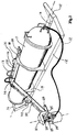
- Fig. 1 is a cylindrical container 11 with a longitudinal main axis, which contains registering and reporting equipment, and a power supply for the operation of a submerged sensor node.
- the container 11 is supported by two parallel skids 12, 13, which are made of a pipe material, which have upwardly bent ends 14, 15, that are connected to each other.
- a yoke 16, with a lifting bow 17, is coupled to the top side of the container 11.
- the yoke 16 is coupled to the container 11 with rings 18, 19, which encircle the container 11 at each end of the yoke.
- a carrier arm 20 extends out, which at its inner end is removably attached to the yoke 16, and at its outer end carries an outwardly extending bracket 21.
- the bracket 21 has a downwardly extending, releasable fastener 22, for coupling to a carrier bracket 23 located on the top of a sensor node 24.
- the carrier bracket 23 can be arranged for gripping by an ROV or an ROT, so that the sensor node 24 can be moved by means of such an auxiliary device.
- the releasable fastener 22 which is biased with a mechanical spring (not shown), comprises a latch pin 25 that can be pulled out with a wire (not shown) to release the sensor node 24 when the carrier arm 20 is to be pulled up.
- the carrier arm 20 is releasably coupled to the yoke 16 with an upside down U-clamp 26, which is held in position by a remotely releasable locking means (not shown).
- a carrier arm 27 This is similar to the carrier arm 20, and is located symmetrically to this about the main axis.
- a horizontal support plate 28 is mounted at the outer end of the carrier arm 27, . This comes into contact with the seabed as the sensor node 24 penetrates the seabed.
- the outer end of the carrier arm 20 has a similar horizontal support plate 29. The vertical placing of the plate 29 is such that it comes into contact with the seabed, when the lower part of the sensor node has been inserted into the seabed.
- the respective areas of the support plates are chosen so that the area-moment of the support plate 28, about the main axis, is approximately the sum of the area-moment of the support plate 29 and the sensor node 24, when the lower part of this is inserted into the seabed.
- Replaceable weights 30 and 31 can be attached to each carrier arm 20 and 27, to adapt the overall system weight when in water, to the solidity and density of the seabed in question. It also helps to balance the structure about the main axis. This solution ensures that the sensor node 24 is forced vertically into the seabed, and that the U-clamp 26 is not jammed to the yoke 16 when these are separated from each other.
- the overall system including the container 11, the carrier arm 20, and the sensor node 24, is deployed either with a wire or with a cable.
- the actuators may be acoustic triggered mechanical springs, electric, or hydraulic.
- the sensor node 24 is connected to the container 11 through an acoustically insulated signal cable 32. This may serve as a lifting means when the sensor nodes are collected.
- the signal cable 32 is of adequately length to avoid tightening when the sensor node 24 is inserted into the seabed.
- the illustrated equipment When deploying, the illustrated equipment is lowered to the chosen position.
- the position can be determined precisely in a co-ordinate system with GPS.
- the weight of the apparatus which shall be lowered can be adapted according to the seabed conditions, so that the sensor node 24 is forced down with sufficient force.
- With a two-axis inclinometer the orientation of the sensor node 24 can be monitored, so that it is inserted with an accurate vertical axis. If the orientation of the sensor node 24 is considered to be acceptable, the latch pin 25 is pulled out without a change of position, and the carrier arm 20 can be lifted up so that the area adjacent to the sensor node is not disturbed.
- Fig. 2 illustrates an alternative embodiment of a sensor arrangement including a container 33, which corresponds to the container 11 in Fig. 1.
- Container 33 can be identical to this.
- the container 33 is attached beneath a deployment frame 34.
- the deployment frame 34 has a central stem 35, which is in the shape of a short, tube-formed part with a vertical axis, with four lateral extending arms 36, 37, 38, and 39 that extend pairwise in opposite directions, with a mutual angle between the arms in each pair 36, 37 and 38, 39.
- a bar-shaped, vertically oriented leg 40 is arranged, with a shoe 41 at a pointed end 42.
- the legs 40 can be connected to a motor (not shown), which can be controlled for individually raising and lowering the legs.
- the legs 40 can be released with a remotely controlled latch for each leg, so that they fall down onto the seabed. Then the latches can be reactivated, so that the deployment frame 34 stays horizontal until it is to be lifted away.
- the deployment frame 34 has a cross beam 43 between two of the arms 36, 37 at one end.
- the cross beam 43 may for instance be formed with a case profile with a central, downward facing recess 44.
- the recess 44 has two opposite flanges 45, 46 at the lower edge, which extend into and define an opening that gives room for the upper part of a sensor node 24, as described in connection with Fig. 1.
- the flanges 45, 46 bear against the upper side of the lower part of the sensor node 24.
- Fig. 3 illustrates the recess 44 in more detail. It shows two gripping claws 47, 48 at the upper edge, which hold onto the carrier bracket 23 located on the top of the sensor node 24, before the deployment of the sensor node 24.
- the gripping claws 47, 48 are releasable by remote control, and are released after the lower part of the sensor node 24 has been forced into the seabed.
- a thruster unit 49 located within a tube 50, with a traverse axis with regard to the longitudinal axis of the deployment frame. This can be operated in the cases where one desires to change the compass direction of the deployment frame 34, for instance, when deploying in an area with a current, where one can make the deployment frame less exposed to currents.
- a tilting meter for instance a gyro with a sensor for pitch, roll, and direction, an altimeter, and an acoustic position transponder.
- a video camera, a water depth meter, and a contact sensor for registering contact with the seabed can be installed.
- a line 51 is used for the deployment of the deployment frame 34 from a vessel.
- a line 51 is used above the deployment frame 34, it branches off into four branch lines 52, which each extend out to an attachment point 53 at the free end of each arm 36-39.
- branch lines 52 stay clear off the deployment frame 34, a floating body (not shown) is arranged at the branch point 54.
- the line 51 is attached to the branch point 54.
- the container 33 is attached to the deployment frame 34 with a releasable attachment arrangement, so that the deployment frame can be released before it is raised up again.
- the active length of the legs 40 can be adapted so that the deployment frame rests against the seabed when a part of the skirt of the sensor node 24 has penetrated down into the loose floor mass.
- the invention comprises a method for deploying sensor nodes, where a sensor node is attached to a deployment frame, and a container for containment of data registration equipment, which is lowered down into the sea.
- the deployment frame 34 is lowered until the sensor node 24 has penetrated down into the seabed, after which the shoe members 41, 42 of the deployment frame are lowered until they come into contact with the seabed, in a position that keeps the deployment frame horizontal, after which the sensor node and the container can be released and the deployment frame can be raised up to a support vessel.
- It also comprises a method for retrieving the deployment frame 34 after the sensor node 24 has been released.
- the shoe members 41, 42 of the deployment frame 34 are kept in contact with the seabed until the deployment frame has been lifted up from the container and the sensor node, to reduce the risk of altering the orientation of the sensor node.
- the deployment frame 34 can be modified in different ways, with more or less arms, or with a square or ring shape.
- the flanges 45, 46 can have built-in force sensors, which register when the sensor node 24 touches the seabed, and measure the downward insertion force.
Landscapes
- Life Sciences & Earth Sciences (AREA)
- Physics & Mathematics (AREA)
- Engineering & Computer Science (AREA)
- Acoustics & Sound (AREA)
- Environmental & Geological Engineering (AREA)
- Geology (AREA)
- Remote Sensing (AREA)
- General Life Sciences & Earth Sciences (AREA)
- General Physics & Mathematics (AREA)
- Geophysics (AREA)
- Oceanography (AREA)
- Geophysics And Detection Of Objects (AREA)
Abstract
Description
Claims (9)
- Arrangement for deployment of seismic sensor units, such as sensor nodes (24), on the seabed, with a frame structure that carries a container (11; 33) for containment of a data registration unit, which is adapted for remotely controlled registration of seismic data, collected by a connected sensor unit, and for containment of additional auxiliary equipment for the sensor node (24), and with supports (12, 13; 36 - 42) that can rest against the seabed and with an attachment means (17; 52, 53) for a lifting hook, for the lifting and lowering by means of a crane, where a holder (20, 47 - 48) exists for the sensor node (24), which shall be lowered down together with the container (11;33) and positioned on the seabed and which is connected to the container through a signal cable (32), characterized in thatit comprises a releasable attachment means (22; 47, 48), which holds the sensor node (24) in a downward extending position with regard to the frame structure that carries the container (11; 33),as the attachment means (22; 47, 48) is arranged with a horizontal distance from the container (11; 33), andwhere a latch mechanism (25) for the attachment means (22; 47, 48) is adapted for releasable holding of the sensor node (24).
- Arrangement according to claim 1, characterized in that the attachment means (22) for the sensor node (24) is arranged on a carrier arm (20), which extends laterally out from the container (11).
- Arrangement according to claim 2, characterized in that the carrier arm (20) at its inner end is provided with a gripping collar (26), which can be releasably attached to elements (16) on the container (11).
- Arrangement according to any one of the claims 1 - 3, characterized in that the latch mechanism is a latch pin (25) that can be pulled out for release before raising.
- Arrangement according to claim 1, characterized in that it comprises a deployment frame (34), which has at least three legs (36 - 39) that extend out from a central carrier (35) with a leg (40) that can be lowered at each free end.
- Arrangement according to any one of the claims 1 - 5, characterized in that it comprises a thruster unit (47) for the control of the direction of the deployment frame (34) with regard to sea currents, waves, and the inclination of the seabed.
- Arrangement according to claim 6, characterized in that it comprises transducers and sensors for water pressure, inclination, altitude above the seabed, direction, and/or position.
- Method for deployment of sensor nodes, where a sensor node is attached to a deployment frame with a container for data registration equipment, which is lowered down into the sea, characterized in that the deployment frame (34) is lowered down until the sensor node (24) has penetrated into the seabed, after which the shoe members (41, 42) of the deployment frame are lowered down until they come into contact with the seabed in a position that keeps the deployment frame horizontal, after which the sensor node and the container are released and the deployment frame is raised up to a support vessel.
- Method according to claim 8, for retrieving the deployment frame (34) after the sensor node (24) has been released, characterized in that the shoe members (41, 42) of the deployment frame (34) are kept in contact with the seabed until the deployment frame is raised up from the container and the sensor node, to reduce the risk of altering the position of the sensor node.
Applications Claiming Priority (2)
| Application Number | Priority Date | Filing Date | Title |
|---|---|---|---|
| NO20041900A NO334545B1 (en) | 2004-05-07 | 2004-05-07 | Device and method for launching seismic sensor devices on the seabed |
| NO20041900 | 2004-07-05 |
Publications (3)
| Publication Number | Publication Date |
|---|---|
| EP1593987A2 true EP1593987A2 (en) | 2005-11-09 |
| EP1593987A3 EP1593987A3 (en) | 2011-10-26 |
| EP1593987B1 EP1593987B1 (en) | 2019-01-23 |
Family
ID=34880509
Family Applications (1)
| Application Number | Title | Priority Date | Filing Date |
|---|---|---|---|
| EP05251827.1A Expired - Lifetime EP1593987B1 (en) | 2004-05-07 | 2005-03-23 | Deployment of seismic sensor |
Country Status (4)
| Country | Link |
|---|---|
| US (1) | US7675821B2 (en) |
| EP (1) | EP1593987B1 (en) |
| MX (1) | MXPA05004783A (en) |
| NO (1) | NO334545B1 (en) |
Cited By (2)
| Publication number | Priority date | Publication date | Assignee | Title |
|---|---|---|---|---|
| NO20200051A1 (en) * | 2020-01-15 | 2021-07-16 | Shearwater Invest As | Method for deployment of ocean seabed node |
| US12529814B2 (en) | 2020-10-09 | 2026-01-20 | Stryde Limited | Systems and methods for deploying seismic nodes |
Families Citing this family (21)
| Publication number | Priority date | Publication date | Assignee | Title |
|---|---|---|---|---|
| US7310287B2 (en) | 2003-05-30 | 2007-12-18 | Fairfield Industries Incorporated | Method and apparatus for seismic data acquisition |
| US8534959B2 (en) | 2005-01-17 | 2013-09-17 | Fairfield Industries Incorporated | Method and apparatus for deployment of ocean bottom seismometers |
| US8075223B2 (en) * | 2009-03-27 | 2011-12-13 | The United States Of America As Represented By The Secretary Of The Navy | Deployment system for fiber-optic line sensors |
| US9720116B2 (en) | 2012-11-02 | 2017-08-01 | Fairfield Industries Incorporated | Land based unit for seismic data acquisition |
| US9381986B2 (en) | 2012-11-21 | 2016-07-05 | Seabed Geosolutions B.V. | Jet-pump-based autonomous underwater vehicle and method for coupling to ocean bottom during marine seismic survey |
| US9457879B2 (en) | 2012-12-17 | 2016-10-04 | Seabed Geosolutions B.V. | Self-burying autonomous underwater vehicle and method for marine seismic surveys |
| US20150003194A1 (en) * | 2013-06-26 | 2015-01-01 | Cgg Services Sa | Directional self-burying sensor system and method |
| US9768626B2 (en) | 2014-08-19 | 2017-09-19 | Seabed Geosolutions B.V. | Simultaneous charging of a plurality of autonomous seismic nodes |
| US9873496B2 (en) | 2014-10-29 | 2018-01-23 | Seabed Geosolutions B.V. | Deployment and retrieval of seismic autonomous underwater vehicles |
| EP3213121B1 (en) | 2014-10-29 | 2021-05-05 | Seabed Geosolutions B.V. | Touch down monitoring of an ocean bottom seismic node |
| CA2974009A1 (en) * | 2015-01-14 | 2016-07-21 | Ion Geophysical Corporation | Ocean sensor system |
| US10514473B2 (en) | 2015-05-29 | 2019-12-24 | Seabed Geosolutions B.V. | Seabed coupling plate for an ocean bottom seismic node |
| US10345462B2 (en) | 2015-05-29 | 2019-07-09 | Seabed Geosolutions B.V. | Flat contact quick connect connection for an autonomous seismic node |
| US10641914B2 (en) | 2016-10-17 | 2020-05-05 | Seabed Geosolutions B.V. | Removable fastening mechanism for marine deployment of autonomous seismic nodes |
| US11442191B2 (en) | 2017-05-02 | 2022-09-13 | Seabed Geosolutions B.V. | System and method for deploying ocean bottom seismic nodes using a plurality of underwater vehicles |
| NO344540B1 (en) | 2018-03-21 | 2020-01-27 | Magseis Asa | System for attaching subsea equipment to a line |
| EP4276008A3 (en) | 2018-05-23 | 2024-05-29 | Blue Ocean Seismic Services Limited | An autonomous data acquisition system |
| CN111399058A (en) * | 2020-04-28 | 2020-07-10 | 中国石油大学(华东) | Combined type submarine earthquake acquisition node |
| WO2024161139A1 (en) | 2023-02-01 | 2024-08-08 | Pxgeo Uk Limited | System and method for using autonomous underwater vehicles for ocean bottom seismic nodes |
| EP4662514A1 (en) | 2023-02-10 | 2025-12-17 | PXGEO UK Limited | Autonomous seismic node for the seabed |
| WO2025168935A1 (en) | 2024-02-06 | 2025-08-14 | Pxgeo Uk Limited | System and method for using autonomous underwater vehicles for ocean bottom seismic nodes |
Family Cites Families (28)
| Publication number | Priority date | Publication date | Assignee | Title |
|---|---|---|---|---|
| US4007436A (en) * | 1975-07-07 | 1977-02-08 | Her Majesty The Queen In Right Of Canada As Represented By The Minister Of National Defense | Self-deploying instrument assembly |
| FR2353866A1 (en) * | 1976-06-04 | 1977-12-30 | Nal Expl Des Oceans Centre | SIGNAL SENSOR, SUCH AS A SISMOGRAPH, USABLE AT THE SEA BOTTOM |
| US4300254A (en) * | 1980-04-28 | 1981-11-17 | Mobil Oil Corporation | Release mechanism for underwater device, such as seismograph |
| US4462094A (en) * | 1980-06-19 | 1984-07-24 | Mobil Oil Corporation | Method and apparatus for determining angle of inclination of seismometer and leveling seismic motion detectors |
| US4446537A (en) * | 1980-06-27 | 1984-05-01 | Mobil Oil Corporation | Electronic system for release of on-bottom seismometer unit |
| US4442916A (en) * | 1980-12-04 | 1984-04-17 | Conoco Inc. | Underwater shear wave vibrator coupling |
| US4516227A (en) * | 1981-12-04 | 1985-05-07 | Marathon Oil Company | Subocean bottom explosive seismic system |
| US4780863A (en) * | 1984-01-04 | 1988-10-25 | Mobil Oil Corporation | Removable power supply for an ocean bottom seismometer |
| US4838379A (en) * | 1987-10-23 | 1989-06-13 | Geosource, Inc. | Geophone implanting and positioning apparatus |
| US4870625A (en) * | 1988-09-26 | 1989-09-26 | Exxon Production Research Company | Marine shear-wave detection system using single mode reflection boundary conversion technique |
| US5007031A (en) * | 1988-12-30 | 1991-04-09 | Union Oil Company Of California | Apparatus for positioning geophones in shallow holes |
| US4924449A (en) * | 1989-04-13 | 1990-05-08 | Nordco Limited | Acoustic sub-surface interrogator |
| NO168557C (en) * | 1989-10-26 | 1992-03-04 | Norske Stats Oljeselskap | SEISMIC DEVICE. |
| NO168611C (en) * | 1989-10-26 | 1992-03-11 | Norske Stats Oljeselskap | SEISMIC CABLE DEVICE |
| US5142499A (en) * | 1991-02-25 | 1992-08-25 | Fletcher Gerald L | Method and apparatus for shallow water seismic operations |
| US5243565A (en) * | 1991-08-13 | 1993-09-07 | University Of Miami | Method of measuring directional spectra of surface gravity waves |
| NO178358C (en) * | 1993-02-25 | 1996-03-06 | Statoil As | Procedure for conducting marine, seismic measurements, and seismic seabed cable for carrying out this method |
| US5654939A (en) * | 1996-02-08 | 1997-08-05 | Hazeltine Corporation | Retrievable volumetric/planar acoustic array apparatus |
| US6474254B1 (en) * | 1997-12-30 | 2002-11-05 | Westerngeco Llc | Submarine deployed ocean bottom seismic system |
| FR2795527B1 (en) * | 1999-06-22 | 2001-09-07 | Thomson Marconi Sonar Sas | UNDERWATER SEISMIC PROSPECTION SYSTEM, ESPECIALLY FOR LARGE FUNDS |
| US6814160B1 (en) * | 1999-07-03 | 2004-11-09 | Westerngeco, Llc | Automated seismic geophone deployment |
| NO310747B1 (en) * | 1999-12-10 | 2001-08-20 | Norges Geotekniske Inst | Generator for seismic shear waves with hydrostatic connection to the seabed |
| CA2635367C (en) * | 2001-07-13 | 2011-10-11 | Triton Resources Inc. | Method and apparatus for underwater tree cutting and retrieval |
| GB2387039B (en) * | 2002-02-28 | 2005-10-26 | Abb Offshore Systems Inc | Subsea deployable drum for laying lines |
| US6975560B2 (en) * | 2002-03-27 | 2005-12-13 | Bp Corporation North America Inc. | Geophysical method and apparatus |
| FR2843805B1 (en) * | 2002-08-22 | 2004-12-17 | Inst Francais Du Petrole | METHOD AND DEVICE FOR ACQUISITION FOR SEISMIC EXPLORATION OF A GEOLOGICAL FORMATION BY PERMANENT RECEPTORS IMPLANTED AT THE BOTTOM OF THE SEA |
| NO318314B1 (en) * | 2002-12-09 | 2005-02-28 | Seabed Geophysical As | Sensor device for seismic waves |
| US7210556B2 (en) * | 2004-01-15 | 2007-05-01 | Saipem America Inc. | Method and apparatus for installing a sensor array |
-
2004
- 2004-05-07 NO NO20041900A patent/NO334545B1/en not_active IP Right Cessation
-
2005
- 2005-03-18 US US11/084,277 patent/US7675821B2/en not_active Expired - Lifetime
- 2005-03-23 EP EP05251827.1A patent/EP1593987B1/en not_active Expired - Lifetime
- 2005-05-04 MX MXPA05004783A patent/MXPA05004783A/en active IP Right Grant
Cited By (4)
| Publication number | Priority date | Publication date | Assignee | Title |
|---|---|---|---|---|
| NO20200051A1 (en) * | 2020-01-15 | 2021-07-16 | Shearwater Invest As | Method for deployment of ocean seabed node |
| WO2021145775A1 (en) * | 2020-01-15 | 2021-07-22 | Polarcus Shipholding As | Method for deployment of ocean seabed node |
| NO346161B1 (en) * | 2020-01-15 | 2022-03-28 | Shearwater Invest As | Method for deployment of ocean seabed node |
| US12529814B2 (en) | 2020-10-09 | 2026-01-20 | Stryde Limited | Systems and methods for deploying seismic nodes |
Also Published As
| Publication number | Publication date |
|---|---|
| US20060002230A1 (en) | 2006-01-05 |
| NO20041900D0 (en) | 2004-05-07 |
| EP1593987B1 (en) | 2019-01-23 |
| NO20041900L (en) | 2005-11-08 |
| EP1593987A3 (en) | 2011-10-26 |
| US7675821B2 (en) | 2010-03-09 |
| MXPA05004783A (en) | 2005-11-17 |
| NO334545B1 (en) | 2014-04-07 |
Similar Documents
| Publication | Publication Date | Title |
|---|---|---|
| EP1593987B1 (en) | Deployment of seismic sensor | |
| EP3775492B1 (en) | Device, system and method for collecting samples from a bed of a waterbody | |
| CN101360646B (en) | Recovery of underwater equipment | |
| US10900189B2 (en) | Anchor driving device | |
| CN103713326A (en) | Anti-trawl seabed base of ocean bottom seismograph | |
| EP1674888A2 (en) | Sensor arrangement and method for the installation and moving of this | |
| JP2010207106A (en) | Method for recovering middle-layer floating fish bank and metal fitting for recovery, usable therefor | |
| CN111750920B (en) | Self-separating seabed foundation suitable for weak and inclined seabed and method of laying the same | |
| CN107044917A (en) | Myriametre level deep-sea autonomous type substrate, which is visited, takes device | |
| WO2013140421A1 (en) | A seabed anchoring device | |
| CN108614291A (en) | A kind of anchoring type deep-sea sulfide seismic exploration data reception device and method of reseptance | |
| KR102648692B1 (en) | mooring type monitoring apparatus for marine environment | |
| JP5333751B2 (en) | Suspension frame and heavy structure sinking device and sinking method | |
| US4580926A (en) | Foundation level and orientation tool | |
| KR101368592B1 (en) | Unmanned ship for wave induced current obbservation | |
| JP5773748B2 (en) | Heavy equipment underwater separation device, suspension frame, heavy equipment settling device and settling method | |
| US6132144A (en) | Passive anchor latch | |
| CN217213189U (en) | Seabed micro-motion stratum detection device | |
| CN214356538U (en) | Buoy system | |
| NO346161B1 (en) | Method for deployment of ocean seabed node | |
| JP2002340924A (en) | Marine wind condition observation device and its laying method | |
| EP3670983B1 (en) | A ferry and a method for assembling weights on underwater pipes | |
| NO20150754A1 (en) | System for deploying an instrument at a seafloor | |
| NO349252B1 (en) | A deployment system for deploying equipment to a floor of a body of water from a vessel, and methods of deploying and retrieving equipment | |
| CN120473898A (en) | Submarine cable protection device deployment system and method |
Legal Events
| Date | Code | Title | Description |
|---|---|---|---|
| PUAI | Public reference made under article 153(3) epc to a published international application that has entered the european phase |
Free format text: ORIGINAL CODE: 0009012 |
|
| AK | Designated contracting states |
Kind code of ref document: A2 Designated state(s): AT BE BG CH CY CZ DE DK EE ES FI FR GB GR HU IE IS IT LI LT LU MC NL PL PT RO SE SI SK TR |
|
| AX | Request for extension of the european patent |
Extension state: AL BA HR LV MK YU |
|
| RAP1 | Party data changed (applicant data changed or rights of an application transferred) |
Owner name: SEABIRD TECHNOLOGIES AS |
|
| PUAL | Search report despatched |
Free format text: ORIGINAL CODE: 0009013 |
|
| AK | Designated contracting states |
Kind code of ref document: A3 Designated state(s): AT BE BG CH CY CZ DE DK EE ES FI FR GB GR HU IE IS IT LI LT LU MC NL PL PT RO SE SI SK TR |
|
| AX | Request for extension of the european patent |
Extension state: AL BA HR LV MK YU |
|
| RIC1 | Information provided on ipc code assigned before grant |
Ipc: G01V 1/38 20060101AFI20110922BHEP |
|
| 17P | Request for examination filed |
Effective date: 20120424 |
|
| AKX | Designation fees paid |
Designated state(s): AT BE BG CH CY CZ DE DK EE ES FI FR GB GR HU IE IS IT LI LT LU MC NL PL PT RO SE SI SK TR |
|
| RAP1 | Party data changed (applicant data changed or rights of an application transferred) |
Owner name: SEABED GEOSOLUTIONS AS |
|
| STAA | Information on the status of an ep patent application or granted ep patent |
Free format text: STATUS: EXAMINATION IS IN PROGRESS |
|
| 17Q | First examination report despatched |
Effective date: 20180207 |
|
| REG | Reference to a national code |
Ref country code: DE Ref legal event code: R079 Ref document number: 602005055315 Country of ref document: DE Free format text: PREVIOUS MAIN CLASS: G01V0001380000 Ipc: G01V0001160000 |
|
| RIC1 | Information provided on ipc code assigned before grant |
Ipc: G01V 1/38 19680901ALI20180822BHEP Ipc: G01V 1/16 19680901AFI20180822BHEP |
|
| GRAP | Despatch of communication of intention to grant a patent |
Free format text: ORIGINAL CODE: EPIDOSNIGR1 |
|
| STAA | Information on the status of an ep patent application or granted ep patent |
Free format text: STATUS: GRANT OF PATENT IS INTENDED |
|
| INTG | Intention to grant announced |
Effective date: 20180928 |
|
| GRAS | Grant fee paid |
Free format text: ORIGINAL CODE: EPIDOSNIGR3 |
|
| GRAA | (expected) grant |
Free format text: ORIGINAL CODE: 0009210 |
|
| STAA | Information on the status of an ep patent application or granted ep patent |
Free format text: STATUS: THE PATENT HAS BEEN GRANTED |
|
| RAP1 | Party data changed (applicant data changed or rights of an application transferred) |
Owner name: SEABED GEOSOLUTIONS AS |
|
| AK | Designated contracting states |
Kind code of ref document: B1 Designated state(s): AT BE BG CH CY CZ DE DK EE ES FI FR GB GR HU IE IS IT LI LT LU MC NL PL PT RO SE SI SK TR |
|
| REG | Reference to a national code |
Ref country code: GB Ref legal event code: FG4D |
|
| REG | Reference to a national code |
Ref country code: CH Ref legal event code: EP |
|
| RIC2 | Information provided on ipc code assigned after grant |
Ipc: G01V 1/16 20060101AFI20180822BHEP Ipc: G01V 1/38 20060101ALI20180822BHEP |
|
| REG | Reference to a national code |
Ref country code: AT Ref legal event code: REF Ref document number: 1091888 Country of ref document: AT Kind code of ref document: T Effective date: 20190215 |
|
| REG | Reference to a national code |
Ref country code: IE Ref legal event code: FG4D |
|
| REG | Reference to a national code |
Ref country code: DE Ref legal event code: R096 Ref document number: 602005055315 Country of ref document: DE |
|
| REG | Reference to a national code |
Ref country code: NL Ref legal event code: FP |
|
| PG25 | Lapsed in a contracting state [announced via postgrant information from national office to epo] |
Ref country code: FI Free format text: LAPSE BECAUSE OF FAILURE TO SUBMIT A TRANSLATION OF THE DESCRIPTION OR TO PAY THE FEE WITHIN THE PRESCRIBED TIME-LIMIT Effective date: 20190123 Ref country code: PL Free format text: LAPSE BECAUSE OF FAILURE TO SUBMIT A TRANSLATION OF THE DESCRIPTION OR TO PAY THE FEE WITHIN THE PRESCRIBED TIME-LIMIT Effective date: 20190123 Ref country code: PT Free format text: LAPSE BECAUSE OF FAILURE TO SUBMIT A TRANSLATION OF THE DESCRIPTION OR TO PAY THE FEE WITHIN THE PRESCRIBED TIME-LIMIT Effective date: 20190523 Ref country code: SE Free format text: LAPSE BECAUSE OF FAILURE TO SUBMIT A TRANSLATION OF THE DESCRIPTION OR TO PAY THE FEE WITHIN THE PRESCRIBED TIME-LIMIT Effective date: 20190123 Ref country code: ES Free format text: LAPSE BECAUSE OF FAILURE TO SUBMIT A TRANSLATION OF THE DESCRIPTION OR TO PAY THE FEE WITHIN THE PRESCRIBED TIME-LIMIT Effective date: 20190123 Ref country code: LT Free format text: LAPSE BECAUSE OF FAILURE TO SUBMIT A TRANSLATION OF THE DESCRIPTION OR TO PAY THE FEE WITHIN THE PRESCRIBED TIME-LIMIT Effective date: 20190123 |
|
| REG | Reference to a national code |
Ref country code: AT Ref legal event code: MK05 Ref document number: 1091888 Country of ref document: AT Kind code of ref document: T Effective date: 20190123 |
|
| PG25 | Lapsed in a contracting state [announced via postgrant information from national office to epo] |
Ref country code: IS Free format text: LAPSE BECAUSE OF FAILURE TO SUBMIT A TRANSLATION OF THE DESCRIPTION OR TO PAY THE FEE WITHIN THE PRESCRIBED TIME-LIMIT Effective date: 20190523 Ref country code: BG Free format text: LAPSE BECAUSE OF FAILURE TO SUBMIT A TRANSLATION OF THE DESCRIPTION OR TO PAY THE FEE WITHIN THE PRESCRIBED TIME-LIMIT Effective date: 20190423 Ref country code: GR Free format text: LAPSE BECAUSE OF FAILURE TO SUBMIT A TRANSLATION OF THE DESCRIPTION OR TO PAY THE FEE WITHIN THE PRESCRIBED TIME-LIMIT Effective date: 20190424 |
|
| REG | Reference to a national code |
Ref country code: DE Ref legal event code: R119 Ref document number: 602005055315 Country of ref document: DE |
|
| PG25 | Lapsed in a contracting state [announced via postgrant information from national office to epo] |
Ref country code: EE Free format text: LAPSE BECAUSE OF FAILURE TO SUBMIT A TRANSLATION OF THE DESCRIPTION OR TO PAY THE FEE WITHIN THE PRESCRIBED TIME-LIMIT Effective date: 20190123 Ref country code: SK Free format text: LAPSE BECAUSE OF FAILURE TO SUBMIT A TRANSLATION OF THE DESCRIPTION OR TO PAY THE FEE WITHIN THE PRESCRIBED TIME-LIMIT Effective date: 20190123 Ref country code: IT Free format text: LAPSE BECAUSE OF FAILURE TO SUBMIT A TRANSLATION OF THE DESCRIPTION OR TO PAY THE FEE WITHIN THE PRESCRIBED TIME-LIMIT Effective date: 20190123 Ref country code: DK Free format text: LAPSE BECAUSE OF FAILURE TO SUBMIT A TRANSLATION OF THE DESCRIPTION OR TO PAY THE FEE WITHIN THE PRESCRIBED TIME-LIMIT Effective date: 20190123 Ref country code: CZ Free format text: LAPSE BECAUSE OF FAILURE TO SUBMIT A TRANSLATION OF THE DESCRIPTION OR TO PAY THE FEE WITHIN THE PRESCRIBED TIME-LIMIT Effective date: 20190123 Ref country code: MC Free format text: LAPSE BECAUSE OF FAILURE TO SUBMIT A TRANSLATION OF THE DESCRIPTION OR TO PAY THE FEE WITHIN THE PRESCRIBED TIME-LIMIT Effective date: 20190123 Ref country code: RO Free format text: LAPSE BECAUSE OF FAILURE TO SUBMIT A TRANSLATION OF THE DESCRIPTION OR TO PAY THE FEE WITHIN THE PRESCRIBED TIME-LIMIT Effective date: 20190123 |
|
| REG | Reference to a national code |
Ref country code: CH Ref legal event code: PL |
|
| PG25 | Lapsed in a contracting state [announced via postgrant information from national office to epo] |
Ref country code: LU Free format text: LAPSE BECAUSE OF NON-PAYMENT OF DUE FEES Effective date: 20190323 |
|
| PLBE | No opposition filed within time limit |
Free format text: ORIGINAL CODE: 0009261 |
|
| REG | Reference to a national code |
Ref country code: BE Ref legal event code: MM Effective date: 20190331 |
|
| STAA | Information on the status of an ep patent application or granted ep patent |
Free format text: STATUS: NO OPPOSITION FILED WITHIN TIME LIMIT |
|
| PG25 | Lapsed in a contracting state [announced via postgrant information from national office to epo] |
Ref country code: AT Free format text: LAPSE BECAUSE OF FAILURE TO SUBMIT A TRANSLATION OF THE DESCRIPTION OR TO PAY THE FEE WITHIN THE PRESCRIBED TIME-LIMIT Effective date: 20190123 |
|
| 26N | No opposition filed |
Effective date: 20191024 |
|
| PG25 | Lapsed in a contracting state [announced via postgrant information from national office to epo] |
Ref country code: LI Free format text: LAPSE BECAUSE OF NON-PAYMENT OF DUE FEES Effective date: 20190331 Ref country code: DE Free format text: LAPSE BECAUSE OF NON-PAYMENT OF DUE FEES Effective date: 20191001 Ref country code: IE Free format text: LAPSE BECAUSE OF NON-PAYMENT OF DUE FEES Effective date: 20190323 Ref country code: CH Free format text: LAPSE BECAUSE OF NON-PAYMENT OF DUE FEES Effective date: 20190331 |
|
| PG25 | Lapsed in a contracting state [announced via postgrant information from national office to epo] |
Ref country code: BE Free format text: LAPSE BECAUSE OF NON-PAYMENT OF DUE FEES Effective date: 20190331 Ref country code: SI Free format text: LAPSE BECAUSE OF FAILURE TO SUBMIT A TRANSLATION OF THE DESCRIPTION OR TO PAY THE FEE WITHIN THE PRESCRIBED TIME-LIMIT Effective date: 20190123 |
|
| PG25 | Lapsed in a contracting state [announced via postgrant information from national office to epo] |
Ref country code: TR Free format text: LAPSE BECAUSE OF FAILURE TO SUBMIT A TRANSLATION OF THE DESCRIPTION OR TO PAY THE FEE WITHIN THE PRESCRIBED TIME-LIMIT Effective date: 20190123 |
|
| PGFP | Annual fee paid to national office [announced via postgrant information from national office to epo] |
Ref country code: FR Payment date: 20210325 Year of fee payment: 17 |
|
| PG25 | Lapsed in a contracting state [announced via postgrant information from national office to epo] |
Ref country code: CY Free format text: LAPSE BECAUSE OF FAILURE TO SUBMIT A TRANSLATION OF THE DESCRIPTION OR TO PAY THE FEE WITHIN THE PRESCRIBED TIME-LIMIT Effective date: 20190123 |
|
| PGFP | Annual fee paid to national office [announced via postgrant information from national office to epo] |
Ref country code: GB Payment date: 20210329 Year of fee payment: 17 |
|
| PG25 | Lapsed in a contracting state [announced via postgrant information from national office to epo] |
Ref country code: HU Free format text: LAPSE BECAUSE OF FAILURE TO SUBMIT A TRANSLATION OF THE DESCRIPTION OR TO PAY THE FEE WITHIN THE PRESCRIBED TIME-LIMIT; INVALID AB INITIO Effective date: 20050323 |
|
| PGFP | Annual fee paid to national office [announced via postgrant information from national office to epo] |
Ref country code: NL Payment date: 20210326 Year of fee payment: 17 |
|
| REG | Reference to a national code |
Ref country code: GB Ref legal event code: 732E Free format text: REGISTERED BETWEEN 20220407 AND 20220413 |
|
| REG | Reference to a national code |
Ref country code: NL Ref legal event code: MM Effective date: 20220401 |
|
| GBPC | Gb: european patent ceased through non-payment of renewal fee |
Effective date: 20220323 |
|
| PG25 | Lapsed in a contracting state [announced via postgrant information from national office to epo] |
Ref country code: NL Free format text: LAPSE BECAUSE OF NON-PAYMENT OF DUE FEES Effective date: 20220401 Ref country code: GB Free format text: LAPSE BECAUSE OF NON-PAYMENT OF DUE FEES Effective date: 20220323 Ref country code: FR Free format text: LAPSE BECAUSE OF NON-PAYMENT OF DUE FEES Effective date: 20220331 |