EP1593821A2 - Spline phased multiple sprocket - Google Patents
Spline phased multiple sprocket Download PDFInfo
- Publication number
- EP1593821A2 EP1593821A2 EP05004973A EP05004973A EP1593821A2 EP 1593821 A2 EP1593821 A2 EP 1593821A2 EP 05004973 A EP05004973 A EP 05004973A EP 05004973 A EP05004973 A EP 05004973A EP 1593821 A2 EP1593821 A2 EP 1593821A2
- Authority
- EP
- European Patent Office
- Prior art keywords
- sprocket
- spline
- outer circumference
- face
- mating
- Prior art date
- Legal status (The legal status is an assumption and is not a legal conclusion. Google has not performed a legal analysis and makes no representation as to the accuracy of the status listed.)
- Withdrawn
Links
- 230000013011 mating Effects 0.000 claims abstract description 35
- 230000005540 biological transmission Effects 0.000 claims abstract description 14
- 238000005304 joining Methods 0.000 claims abstract description 11
- 238000000034 method Methods 0.000 claims description 11
- 239000012255 powdered metal Substances 0.000 claims description 9
- 238000005245 sintering Methods 0.000 claims description 9
- 238000005219 brazing Methods 0.000 claims description 7
- 238000004519 manufacturing process Methods 0.000 claims description 6
- 238000003466 welding Methods 0.000 claims description 3
- 238000005272 metallurgy Methods 0.000 claims 5
- 230000004075 alteration Effects 0.000 description 1
- 230000009977 dual effect Effects 0.000 description 1
- 238000000926 separation method Methods 0.000 description 1
Images




Classifications
-
- F—MECHANICAL ENGINEERING; LIGHTING; HEATING; WEAPONS; BLASTING
- F01—MACHINES OR ENGINES IN GENERAL; ENGINE PLANTS IN GENERAL; STEAM ENGINES
- F01L—CYCLICALLY OPERATING VALVES FOR MACHINES OR ENGINES
- F01L1/00—Valve-gear or valve arrangements, e.g. lift-valve gear
- F01L1/34—Valve-gear or valve arrangements, e.g. lift-valve gear characterised by the provision of means for changing the timing of the valves without changing the duration of opening and without affecting the magnitude of the valve lift
- F01L1/344—Valve-gear or valve arrangements, e.g. lift-valve gear characterised by the provision of means for changing the timing of the valves without changing the duration of opening and without affecting the magnitude of the valve lift changing the angular relationship between crankshaft and camshaft, e.g. using helicoidal gear
- F01L1/34403—Valve-gear or valve arrangements, e.g. lift-valve gear characterised by the provision of means for changing the timing of the valves without changing the duration of opening and without affecting the magnitude of the valve lift changing the angular relationship between crankshaft and camshaft, e.g. using helicoidal gear using helically teethed sleeve or gear moving axially between crankshaft and camshaft
- F01L1/34406—Valve-gear or valve arrangements, e.g. lift-valve gear characterised by the provision of means for changing the timing of the valves without changing the duration of opening and without affecting the magnitude of the valve lift changing the angular relationship between crankshaft and camshaft, e.g. using helicoidal gear using helically teethed sleeve or gear moving axially between crankshaft and camshaft the helically teethed sleeve being located in the camshaft driving pulley
-
- F—MECHANICAL ENGINEERING; LIGHTING; HEATING; WEAPONS; BLASTING
- F01—MACHINES OR ENGINES IN GENERAL; ENGINE PLANTS IN GENERAL; STEAM ENGINES
- F01L—CYCLICALLY OPERATING VALVES FOR MACHINES OR ENGINES
- F01L1/00—Valve-gear or valve arrangements, e.g. lift-valve gear
- F01L1/02—Valve drive
-
- F—MECHANICAL ENGINEERING; LIGHTING; HEATING; WEAPONS; BLASTING
- F01—MACHINES OR ENGINES IN GENERAL; ENGINE PLANTS IN GENERAL; STEAM ENGINES
- F01L—CYCLICALLY OPERATING VALVES FOR MACHINES OR ENGINES
- F01L1/00—Valve-gear or valve arrangements, e.g. lift-valve gear
- F01L1/02—Valve drive
- F01L1/022—Chain drive
-
- F—MECHANICAL ENGINEERING; LIGHTING; HEATING; WEAPONS; BLASTING
- F16—ENGINEERING ELEMENTS AND UNITS; GENERAL MEASURES FOR PRODUCING AND MAINTAINING EFFECTIVE FUNCTIONING OF MACHINES OR INSTALLATIONS; THERMAL INSULATION IN GENERAL
- F16H—GEARING
- F16H55/00—Elements with teeth or friction surfaces for conveying motion; Worms, pulleys or sheaves for gearing mechanisms
- F16H55/02—Toothed members; Worms
- F16H55/30—Chain-wheels
-
- F—MECHANICAL ENGINEERING; LIGHTING; HEATING; WEAPONS; BLASTING
- F01—MACHINES OR ENGINES IN GENERAL; ENGINE PLANTS IN GENERAL; STEAM ENGINES
- F01L—CYCLICALLY OPERATING VALVES FOR MACHINES OR ENGINES
- F01L2301/00—Using particular materials
-
- F—MECHANICAL ENGINEERING; LIGHTING; HEATING; WEAPONS; BLASTING
- F01—MACHINES OR ENGINES IN GENERAL; ENGINE PLANTS IN GENERAL; STEAM ENGINES
- F01L—CYCLICALLY OPERATING VALVES FOR MACHINES OR ENGINES
- F01L2303/00—Manufacturing of components used in valve arrangements
-
- F—MECHANICAL ENGINEERING; LIGHTING; HEATING; WEAPONS; BLASTING
- F16—ENGINEERING ELEMENTS AND UNITS; GENERAL MEASURES FOR PRODUCING AND MAINTAINING EFFECTIVE FUNCTIONING OF MACHINES OR INSTALLATIONS; THERMAL INSULATION IN GENERAL
- F16H—GEARING
- F16H55/00—Elements with teeth or friction surfaces for conveying motion; Worms, pulleys or sheaves for gearing mechanisms
- F16H55/02—Toothed members; Worms
- F16H55/30—Chain-wheels
- F16H2055/306—Chain-wheels with means providing resilience or vibration damping in chain sprocket wheels
Definitions
- the invention pertains to the field of power transmission chains. More particularly, the invention pertains to a phased sprocket of multiple pieces for use with a power transmission chain.
- an endless chain is wrapped around at least two sprockets, each of which are supported by shafts. Rotation of the driving sprocket causes power transmission through the chain and results in the movement of the driven sprocket.
- Different combinations, placement, and connection of sprockets have been used in prior power transmission systems to decrease the noise and vibration generated by the contact between the sprockets and the chain.
- US 5,427,580 discloses splitting a conventional sprocket of an engine timing system into two portions, and then offsetting or phasing the portions with respect to one another.
- the conventional single sprocket is replaced by a pair of sprockets that are phased relative to each other by half a pitch and are manufactured as a single unit.
- One of biggest problems with the single unit dual sprocket is the manufacturing cost and complexity. To produce each single unit, complex and extensive tooling using multiple PM tools are used, making the cost of producing a single unit very high.
- US 5,816,968 discloses an idler sprocket assembly where at least two phased sprockets are placed on an idler shaft that are connected by a chain to drive the camshafts.
- the idler camshaft sprockets are manufactured separately and have internal keyways or teeth, which allow the sprockets to be placed on a spline or hub.
- US 5,846,149 discloses a chain and sprocket system which includes phased sprockets.
- the phased sprockets may be formed of one single piece or of two single pieces fused together.
- the sprockets may be split into two portions and then the portions may be phased with respect to one another, with the number of sprockets varying.
- US 5,980,406 discloses two identical sprockets that may be placed on a hub or shaft and are phased with respect to each other.
- the sprockets have projections and grooves on their inner circumferential surface.
- the projections or grooves are splines or keyways.
- the sprockets may also have splines on the face of the sprocket that extends radially, rather than on the inner circumferential surface of the sprocket.
- US 6,267,701 discloses side-by-side sprockets of a phased chain system that are offset and where only one of the sprockets is secured to the drive shaft. The remaining sprocket is independently rotatably and does not transmit power to the shaft. The sprockets are phased with respect to each other.
- US 6,413,180 discloses a first silent chain of the inverted tooth type having all the same links wrapped around a first sprocket and a second chain wrapped around a second sprocket.
- the first sprocket and the second sprocket are mounted in parallel on a drive shaft, and the teeth of the first sprocket are offset from the teeth of the second sprocket.
- the first and second chains only have a single pitch and the sprockets have a random pitch.
- the sprockets may be formed integrally or separate.
- JP 01247858A discloses a first sprocket mounted on a shaft and a second identical sprocket is spline-engaged with a boss part of the sprocket.
- the boss part is coupled to the shaft by a slide clutch.
- the first sprocket and the second sprocket are phased with respect to each other.
- JP62251564 discloses double row sprockets that are split into a pair of identical sprockets that are phased. The separation is in the axial direction.
- the first half-sprocket has a toothed outer circumference for mating with a chain, an inner splined bore for mating with a shaft, and an integral raised portion and an opposing recessed portion on at least one face.
- the second half-sprocket has a toothed outer circumference for mating with a chain, an inner splined bore for mating with a shaft, and an integral raised portion and an opposing recessed portion on at least one face.
- the integral raised portion of the first half-sprocket is received by the recessed portion of the second half-sprocket and the recessed portion of the first half-sprocket receives the integral raised portion of the second half-sprocket, joining the first half-sprocket to the second half-sprocket in a phased relationship.
- the first half-sprocket may have a raised flange with a spline on at least one face of the first half-sprocket.
- the second half-sprocket has an inner bore with at least one spline for mating with the raised flange.
- the inner bore and the at least one spline of the second half-sprocket fits outside and with the at least one spline of the raised flange of the first half-sprocket.
- the half-sprockets are rigidly joined in a phased relationship by brazing or high temperature sintering.
- the inner bore with at least one spline of the first half-sprocket is a 1 ⁇ 4 tooth space off relative to the toothed outer circumference of the first half-sprocket and the inner bore with at least one spline of the second half-sprocket is also a 1 ⁇ 4 tooth space off relative to the toothed outer circumference of the second half-sprocket.
- a first half-sprocket 1 has teeth 2 along its outer circumference for mating with a chain, an inner splined bore 4, and at least one face 6 with an integral raised portion 8, which in this case is semicircular and an opposing recessed portion 10, which in this case is also semicircular.
- Figure 2 shows an exploded view of where the face 8a of the integral raised portion 8 and the recessed portion 10 of the first half-sprocket 1 meet.
- a second single half-sprocket 12 also has teeth 14 along its outer circumference for mating with a chain, an inner splined bore 16, and at least one face 18 with an integral raised portion 22, which in this case is semicircular, and an opposing recessed portion 20, which in this case is also semicircular.
- the raised portions 8, 22 and the recessed portions 10, 20 are used to connect and orient the first half-sprocket 1 relative to the second half-sprocket 12, allowing for rapid assembly.
- the recessed portion 10, in this case semicircular in shape, of the first half-sprocket 1 receives the integral raised portion 22 of the second half-sprocket 12 and likewise, the integral raised portion 8 of the first half-sprocket 1 is received by the recessed portion 20 of the second half-sprocket 12, forming multiple sprocket 500, as shown in Figures 8 and 9, for placement on a hub or drive shaft and mating with chains for the transmission of power.
- the first half-sprocket 1 is phased relative to the second half-sprocket 12 by a half step, although the phase difference between the first half-sprocket 1 and the second half-sprocket 12 may be greater or smaller the half a tooth.
- the clearance 502 is the distance between the toothed outer circumference 2 of the first half-sprocket 1 and the toothed outer circumference 14 of the second half-sprocket 12.
- the clearance 502 is also a direct relationship as to how well the first and second half-sprockets 1, 12 fit together.
- the space between the integral raised portion 22 of the second half-sprocket 12 and the integral raised portion 8 of the first half-sprocket 1 is as close to zero as possible. The tighter the fit between the first and second half-sprockets 1, 12, the less that backlash occurs.
- the number of splines or teeth on the inner splined bores 4, 16 of the half sprockets 1, 12, are not equal to the number of teeth on the outer toothed circumferences 2, 14 of the half-sprockets 1, 12.
- the placement of the integral raised 8, 22 and recessed portions 10, 20 positions the toothed outer circumference of the half-sprockets 1, 12, a half a tooth apart from each other.
- the phase difference between the first half-sprocket 1 and the second half-sprocket 12 may be greater or smaller the half a tooth, with the appropriate alterations made to the placement of the integral raised portions 8, 22 and the recessed portions 10, 20.
- the first and second half-sprockets 1, 12 may be symmetrical about a vertical axis on the faces 6, 18 perpendicular to an axis of rotation of the half-sprocket or asymmetrical about a horizontal axis on the faces 6, 18 parallel to the axis of rotation of the half-sprocket.
- the half-sprockets 1, 12 may also be made up of multiple pieces. If the half-sprockets are symmetrical, the pieces used to assemble each of the single half-sprockets would be interchangeable.
- the first and second half-sprockets 1, 12 are not physically locked in place, and are loosely mounted on the same shaft, however a snap ring (not shown) may be utilized to maintain the axial relationships.
- the tooling used to produce the single half-sprockets 1, 12 can be reduced in number, less complex, and decrease assembly time resulting in an inexpensive phased multiple sprocket 500 that keeps noise levels low.
- a first half-sprocket 100 has teeth 102 along its outer circumference for mating with a chain, an inner splined bore 104 with at least one spline and at least one face 106.
- a second single half-sprocket 112 also has teeth 114 along its outer circumference for mating with a chain, an inner splined bore 116 with at least one spline, and at least one face 118.
- the inner splined bores 104 and 116 are used to set the phase difference.
- the inner splined bore 104 is a 1 ⁇ 4 tooth, or spline space off relative to the center alignment of the outer toothed circumference 102 of the first half-sprocket 100.
- the second half-sprocket 112 has the same inner splined bore 106 with the 1 ⁇ 4 tooth spacing relative to the toothed outer circumference 114.
- the toothed outer circumference 102 of the first half sprocket 100 is half a tooth off from the toothed outer circumference 114 of the second half sprocket 112, forming multiple sprocket 500 as shown in Figures 8 and 9, for placement on a hub or drive shaft and mating with chains for the transmission of power, the toothed outer circumference 102 of the first half sprocket 100 is half a tooth off from the toothed outer circumference 114 of the second half sprocket 112.
- the phase difference between the first half-sprocket 100 and the second half-sprocket 112 may be greater or smaller than half a tooth, with the proper adjustments made to the tooth or spline spacing on the inner splined bore.
- the number of splines or teeth on the inner splined bores 104, 116 of the half sprockets 100, 112 are equal to the number of teeth on the outer toothed circumferences 102, 114 of the half-sprockets 100, 112.
- the first and second half-sprockets 100, 112 may be symmetrical about a vertical axis on the faces 106, 118 perpendicular to an axis of rotation of the half-sprocket or asymmetrical about a horizontal axis on the faces 106, 118 parallel to the axis of rotation of the half-sprocket.
- the half-sprockets 100, 112 may also be made up of multiple pieces.
- first and second half-sprockets 100, 112 are not physically locked in place, and are loosely mounted on the same shaft, however a snap ring (not shown) may be utilized to maintain the axial relationships.
- the tooling used to produce the single half-sprockets 100, 112 can be reduced in number, less complex, and decrease assembly time resulting in an inexpensive phased multiple sprocket 500 that keeps noise levels low.
- a first half-sprocket having teeth 202 along its outer circumference for mating with a chain, an inner splined bore 204, and at least one face 206 with a recessed portion 230, in this case, in the form of a punched hole and an opposing integral raised portion 232, which in this case is a pin.
- a second single half-sprocket 212 also has teeth 214 along its outer circumference for mating with a chain, an inner splined bore 216, and at least one face 218 with an integral raised portion 234, which in this case is a pin and an opposing recessed portion 236, in this case a punched hole, are used to join and orient the first half sprocket 200 relative to the second half-sprocket 212, allowing for rapid assembly.
- the inner splined bores 204 and 216 are used to set the phase difference. Similar to the first embodiment, the inner splined bore 204 is a 1 ⁇ 4 tooth, or spline space off relative to the center alignment of the outer toothed circumference 202 of the first half-sprocket 200.
- the second half-sprocket 212 has the same inner splined bore 206 with the 1 ⁇ 4 tooth spacing relative to the toothed outer circumference 214.
- the toothed outer circumference 202 of the first half sprocket 200 is half a tooth off from the toothed outer circumference 214 of the second half sprocket 212.
- the phase difference between the first half-sprocket 200 and the second half-sprocket 212 may be greater or smaller than half a tooth, with the proper adjustments made to the tooth or spline spacing on the inner splined bore.
- the number of teeth on the toothed outer circumference 202, 214 of the half-sprockets 200, 212 may be equal to the number of splines or teeth on the inner splined bores 204, 216 of the half-sprockets 200, 212.
- the first and second half-sprockets 200, 212 may be symmetrical about a vertical axis on the faces 206, 218 perpendicular to an axis of rotation of the half-sprocket or asymmetrical about a horizontal axis on the faces 206, 218 parallel to the axis of rotation of the half-sprocket.
- the half-sprockets 200, 212 may also be made up of multiple pieces. If the half-sprockets are symmetrical, the pieces used to assemble each of the single half-sprockets would be interchangeable.
- the first and second half-sprockets 200, 212 are not physically locked in place, and are loosely mounted on the same shaft, however a snap ring (not shown) may be utilized to maintain the axial relationships.
- the tooling used to produce the single half-sprockets 200, 212 can be reduced in number, less complex, and decrease assembly time resulting in an inexpensive phased multiple sprocket 500 that keeps noise levels low.
- Figure 6 shows a fourth embodiment of the present invention.
- a first single half-sprocket 300 made of powdered metal has teeth 302 along its outer circumference for mating with a chain, and an inner splined bore 304, and at least one face 306 with an integral raised flange 324 with at least one spline or keyway 326 on the raised flange 324.
- a second half-sprocket 312 also made of powdered metal has teeth 314 along its outer circumference for mating with a chain, and an inner bore 316 with at least one spline or key 328 for mating with the raised flange 324 of the first half-sprocket 300.
- the splines or keyways 326 on the raised flange 324 and the splines or keys 328 are used to connect and orient the first half-sprocket 300 relative to the second half-sprocket 312.
- the half-sprockets 300, 312 are then attached rigidly by brazing or high temperature sintering. In either case, the resultant multiple sprocket 500 may be rapidly assembled.
- the powdered metal comprising the first half-sprocket 300 may have properties that allow it to expand at one rate when heated and the second half-sprocket 312 made of powdered metal may have properties that allow it to expand when heated at a rate smaller than that of the first half-sprocket 300.
- the splines or keys 328 on the inner bore 316 of the second half-sprocket 312 are received by the splines or keyways 326 on the raised flange 324 of the first half-sprocket 300 form a single multiple sprocket 500, as shown in Figures 8 and 9, for placement on a hub or drive shaft and mating with chains for transmission of power, where the first half-sprocket 300 is phased relative to the second half-sprocket 312 and the half-sprockets are rigidly joined to each other by brazing or high temperature sintering.
- Other methods of rigidly joining the half-sprocket include heat shrinking and welding.
- the clearance 502 is the distance between the toothed outer circumference 302 of the first half-sprocket 300 and the toothed outer circumference 314 of the second half-sprocket 312, and the clearance is a direct relationship as to how well the first and second half-sprockets 300, 312 fit together.
- the tooling used to produce the single half-sprockets 300, 312 can be reduced in number, less complex, and decrease assembly time resulting in an inexpensive phased multiple sprocket 500 that keeps noise levels low.
- a first half-sprocket 400 made of powdered metal has teeth 402 along its outer circumference for mating with a chain, an inner splined bore 404, and at least one face 406 with an integral raised flange 424 which has multiple splines or keyways 426.
- a second half-sprocket 412 also made of powdered metal has teeth 414 along its outer circumference for mating with a chain and an inner bore 416 with multiple splines or keys 428.
- the raised flange 424 and the inner bore 416 with multiple splines or keys 428 are used to connect and orient the first half-sprocket 400 relative to the second half-sprocket 412.
- the half-sprockets 400, 412 are then attached rigidly by brazing or high temperature sintering. In either case, the resultant multiple sprocket 500 may be rapidly assembled. If the half-sprockets 400, 412 are joined rigidly by high temperature sintering, the powdered metal comprising the first half-sprocket 400 may have properties that allow it to expand at one rate when heated and the second half-sprocket 412 made of powdered metal may have properties that allow it to expand when heated at a rate smaller than that of the first half-sprocket 400.
- the integral raised flange 424 with multiple splines or keyways 426 of the first half-sprocket 400 receives the multiple splines or keys 428 of the inner bore 416 of the second half-sprocket 412, forming a multiple sprocket 500, as shown in Figures 8 and 9, for placement on a hub or drive shaft and receiving chains that transmit power and the first half-sprocket 400 is phased relative to the second half-sprocket 412 and the half-sprockets are rigidly joined to each other by brazing or high temperature sintering.
- Other methods of rigidly joining the half-sprocket include heat shrinking and welding.
- the clearance 502 is the distance between the toothed outer circumference 402 of the first half-sprocket 400 and the toothed outer circumference 414 of the second half-sprocket 412, and the clearance is a direct relationship as to how well the first and second half-sprockets 400, 412 fit together.
- the tooling used to produce the single half-sprockets 400, 412 can be reduced in number, less complex, and decrease assembly time resulting in an inexpensive phased multiple sprocket 500 that keeps noise levels low.
- a conventional sprocket paired with a random chain, a Gemini one piece sprocket, and a spline phased sprocket were all tested using four center mics at speed range averages of 500 to 300 RPM. Two tests were performed on each chain and sprocket assembly and an average of the two tests conducted for each was calculated.
- the pitch frequency for the spline phased sprocket of the present invention was 1.9 dBA higher and the overall level was 0.3 d BA higher than the one piece Gemini sprocket system, which to the human ear is indiscernible.
- the spline phased sprocket shows an average improvement of 10.8 dBA for pitch frequency and 1.8 dBA for overall noise. As shown below, the spline phased sprocket still provides a significantly lower level of noise than the conventional random chain.
- the noise of the multiple sprocket comprised of single half-sprockets offers lower production costs, easier tooling, manufacturing, and in comparison to the prior art one piece sprockets, comparable noise levels.
Landscapes
- Engineering & Computer Science (AREA)
- General Engineering & Computer Science (AREA)
- Mechanical Engineering (AREA)
- Gears, Cams (AREA)
Abstract
Multiple sprocket for transmission of power from a splined shaft to at least two chains,
the multiple sprocket comprising a first half-sprocket (200) and at least one second half
sprocket (212). The first half-sprocket (200) has a toothed outer circumference for mating with a
chain, an inner splined bore (204) for mating with a shaft, and an integral raised portion (232) and
an opposing recessed portion (230) on at least one face. The second half-sprocket has a
toothed outer circumference for mating with a chain, an inner splined bore (216) for mating
with a shaft, and an integral raised portion (234) and an opposing recessed portion (236) on at least
one face. The integral raised portion (232) of the first half-sprocket is received by the
recessed portion (236) of the second half-sprocket (212) and the recessed portion (230) of the first half
sprocket (200) receives the integral raised portion (234) of the second half-sprocket (212), joining the
first half-sprocket (200) to the second half-sprocket (212) in a phased relationship.
Description
- The invention pertains to the field of power transmission chains. More particularly, the invention pertains to a phased sprocket of multiple pieces for use with a power transmission chain.
- In a conventional power transmission system, an endless chain is wrapped around at least two sprockets, each of which are supported by shafts. Rotation of the driving sprocket causes power transmission through the chain and results in the movement of the driven sprocket. Different combinations, placement, and connection of sprockets have been used in prior power transmission systems to decrease the noise and vibration generated by the contact between the sprockets and the chain.
- US 5,427,580 discloses splitting a conventional sprocket of an engine timing system into two portions, and then offsetting or phasing the portions with respect to one another. In another embodiment, the conventional single sprocket is replaced by a pair of sprockets that are phased relative to each other by half a pitch and are manufactured as a single unit. One of biggest problems with the single unit dual sprocket is the manufacturing cost and complexity. To produce each single unit, complex and extensive tooling using multiple PM tools are used, making the cost of producing a single unit very high.
- US 5,816,968 discloses an idler sprocket assembly where at least two phased sprockets are placed on an idler shaft that are connected by a chain to drive the camshafts. The idler camshaft sprockets are manufactured separately and have internal keyways or teeth, which allow the sprockets to be placed on a spline or hub.
- US 5,846,149 discloses a chain and sprocket system which includes phased sprockets. The phased sprockets may be formed of one single piece or of two single pieces fused together. The sprockets may be split into two portions and then the portions may be phased with respect to one another, with the number of sprockets varying.
- US 5,980,406 discloses two identical sprockets that may be placed on a hub or shaft and are phased with respect to each other. The sprockets have projections and grooves on their inner circumferential surface. The projections or grooves are splines or keyways. The sprockets may also have splines on the face of the sprocket that extends radially, rather than on the inner circumferential surface of the sprocket.
- US 6,267,701 discloses side-by-side sprockets of a phased chain system that are offset and where only one of the sprockets is secured to the drive shaft. The remaining sprocket is independently rotatably and does not transmit power to the shaft. The sprockets are phased with respect to each other.
- US 6,413,180 discloses a first silent chain of the inverted tooth type having all the same links wrapped around a first sprocket and a second chain wrapped around a second sprocket. The first sprocket and the second sprocket are mounted in parallel on a drive shaft, and the teeth of the first sprocket are offset from the teeth of the second sprocket. The first and second chains only have a single pitch and the sprockets have a random pitch. The sprockets may be formed integrally or separate.
- JP 01247858A discloses a first sprocket mounted on a shaft and a second identical sprocket is spline-engaged with a boss part of the sprocket. The boss part is coupled to the shaft by a slide clutch. The first sprocket and the second sprocket are phased with respect to each other.
- JP62251564 discloses double row sprockets that are split into a pair of identical sprockets that are phased. The separation is in the axial direction.
- A multiple sprocket for transmission of power from a splined shaft to at least two chains, the multiple sprocket comprising a first half-sprocket and at least one second half- sprocket. The first half-sprocket has a toothed outer circumference for mating with a chain, an inner splined bore for mating with a shaft, and an integral raised portion and an opposing recessed portion on at least one face. The second half-sprocket has a toothed outer circumference for mating with a chain, an inner splined bore for mating with a shaft, and an integral raised portion and an opposing recessed portion on at least one face. The integral raised portion of the first half-sprocket is received by the recessed portion of the second half-sprocket and the recessed portion of the first half-sprocket receives the integral raised portion of the second half-sprocket, joining the first half-sprocket to the second half-sprocket in a phased relationship.
- Alternatively, the first half-sprocket may have a raised flange with a spline on at least one face of the first half-sprocket. The second half-sprocket has an inner bore with at least one spline for mating with the raised flange. The inner bore and the at least one spline of the second half-sprocket fits outside and with the at least one spline of the raised flange of the first half-sprocket. The half-sprockets are rigidly joined in a phased relationship by brazing or high temperature sintering.
- In a further embodiment, the inner bore with at least one spline of the first half-sprocket is a ¼ tooth space off relative to the toothed outer circumference of the first half-sprocket and the inner bore with at least one spline of the second half-sprocket is also a ¼ tooth space off relative to the toothed outer circumference of the second half-sprocket. When either the first half-sprocket or the second half-sprocket is flipped relative to the other, the faces of the first half-sprocket and the second half-sprocket meet, forming the multiple sprocket, where the first half-sprocket is phased relative to the second half-sprocket.
-
- Fig. 1 shows two half-sprockets that form a multiple sprocket of a first embodiment, where the number of splines on the inner splined bore does not equal the number of teeth on the outer circumference of the half-sprockets.
- Fig. 2 shows an exploded view of the first half-sprocket of the first embodiment of Figure 1.
- Fig. 3 shows the alignment of the splines on the inner splined bore relative to the teeth on the outer circumference of the first half-sprocket of the second embodiment.
- Fig. 4 shows two half-sprockets that form a multiple sprocket of a second embodiment, where the number of splines on the inner splined bore equals the number of teeth on the outer circumference of the half-sprockets.
- Fig. 5 shows an alternative for securing two half-sprockets together to form a multiple half-sprocket of a third embodiment.
- Fig. 6 shows fourth alternative for securing two half-sprockets together to form the multiple sprocket of a third embodiment.
- Fig. 7 shows another alternate for securing two half-sprockets together to form the multiple sprocket of a fourth embodiment.
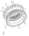
- Fig. 8 shows a side profile of the assembled multiple sprocket.
- Fig. 9 shows a front face view of the assembled multiple sprocket.
-
- Referring to Figure 1, a first half-sprocket 1 has
teeth 2 along its outer circumference for mating with a chain, an innersplined bore 4, and at least oneface 6 with an integral raisedportion 8, which in this case is semicircular and an opposingrecessed portion 10, which in this case is also semicircular. Figure 2 shows an exploded view of where theface 8a of the integral raisedportion 8 and therecessed portion 10 of the first half-sprocket 1 meet. A second single half-sprocket 12 also hasteeth 14 along its outer circumference for mating with a chain, an innersplined bore 16, and at least oneface 18 with an integral raisedportion 22, which in this case is semicircular, and an opposingrecessed portion 20, which in this case is also semicircular. The raisedportions portions sprocket 12, allowing for rapid assembly. - When the first and second single half-
sprockets 1, 12 are fitted together, therecessed portion 10, in this case semicircular in shape, of the first half-sprocket 1 receives the integral raisedportion 22 of the second half-sprocket 12 and likewise, the integral raisedportion 8 of the first half-sprocket 1 is received by therecessed portion 20 of the second half-sprocket 12, formingmultiple sprocket 500, as shown in Figures 8 and 9, for placement on a hub or drive shaft and mating with chains for the transmission of power. In themultiple sprocket 500, the first half-sprocket 1 is phased relative to the second half-sprocket 12 by a half step, although the phase difference between the first half-sprocket 1 and the second half-sprocket 12 may be greater or smaller the half a tooth. The clearance 502 is the distance between the toothedouter circumference 2 of the first half-sprocket 1 and the toothedouter circumference 14 of the second half-sprocket 12. The clearance 502 is also a direct relationship as to how well the first and second half-sprockets 1, 12 fit together. Ideally, the space between the integral raisedportion 22 of the second half-sprocket 12 and the integral raisedportion 8 of the first half-sprocket 1 is as close to zero as possible. The tighter the fit between the first and second half-sprockets 1, 12, the less that backlash occurs. - In this embodiment, the number of splines or teeth on the inner
splined bores half sprockets 1, 12, are not equal to the number of teeth on theouter toothed circumferences sprockets 1, 12. When the two half-sprockets 1, 12, are joined together, the placement of the integral raised 8, 22 and recessedportions sprockets 1, 12, a half a tooth apart from each other. The phase difference between the first half-sprocket 1 and the second half-sprocket 12 may be greater or smaller the half a tooth, with the appropriate alterations made to the placement of the integral raisedportions portions - The first and second half-
sprockets 1, 12 may be symmetrical about a vertical axis on thefaces faces sprockets 1, 12 may also be made up of multiple pieces. If the half-sprockets are symmetrical, the pieces used to assemble each of the single half-sprockets would be interchangeable. The first and second half-sprockets 1, 12 are not physically locked in place, and are loosely mounted on the same shaft, however a snap ring (not shown) may be utilized to maintain the axial relationships. - By using two single half-
sprockets 1, 12 to form amultiple sprocket 500, the tooling used to produce the single half-sprockets 1, 12 can be reduced in number, less complex, and decrease assembly time resulting in an inexpensive phasedmultiple sprocket 500 that keeps noise levels low. - In a second embodiment, shown in Figure 4, a first half-
sprocket 100 hasteeth 102 along its outer circumference for mating with a chain, an inner splined bore 104 with at least one spline and at least oneface 106. A second single half-sprocket 112 also hasteeth 114 along its outer circumference for mating with a chain, an inner splined bore 116 with at least one spline, and at least oneface 118. The inner splined bores 104 and 116 are used to set the phase difference. As shown in Figure 3, the innersplined bore 104 is a ¼ tooth, or spline space off relative to the center alignment of the outertoothed circumference 102 of the first half-sprocket 100. The second half-sprocket 112 has the same innersplined bore 106 with the ¼ tooth spacing relative to the toothedouter circumference 114. When the first half-sprocket 100 is reversed and joined with the second half-sprocket 212, the toothedouter circumference 102 of thefirst half sprocket 100 is half a tooth off from the toothedouter circumference 114 of thesecond half sprocket 112, formingmultiple sprocket 500 as shown in Figures 8 and 9, for placement on a hub or drive shaft and mating with chains for the transmission of power, the toothedouter circumference 102 of thefirst half sprocket 100 is half a tooth off from the toothedouter circumference 114 of thesecond half sprocket 112. The phase difference between the first half-sprocket 100 and the second half-sprocket 112 may be greater or smaller than half a tooth, with the proper adjustments made to the tooth or spline spacing on the inner splined bore. - In this embodiment, the number of splines or teeth on the inner splined bores 104, 116 of the
half sprockets toothed circumferences sprockets sprockets faces faces sprockets sprockets - By using two single half-
sprockets 110, 112 to form amultiple sprocket 500, the tooling used to produce the single half-sprockets multiple sprocket 500 that keeps noise levels low. - In a third embodiment, shown in Figure 5, a first half-
sprocket having teeth 202 along its outer circumference for mating with a chain, an innersplined bore 204, and at least oneface 206 with a recessedportion 230, in this case, in the form of a punched hole and an opposing integral raisedportion 232, which in this case is a pin. A second single half-sprocket 212 also hasteeth 214 along its outer circumference for mating with a chain, an innersplined bore 216, and at least oneface 218 with an integral raisedportion 234, which in this case is a pin and an opposing recessedportion 236, in this case a punched hole, are used to join and orient thefirst half sprocket 200 relative to the second half-sprocket 212, allowing for rapid assembly. - When the first half-
sprocket 200 is reversed or flipped (towards you as you view the Figure), the two faces 206, 218 of the first half-sprocket 200 and the second half-sprocket 212 meet, and a singlemultiple sprocket 500 results, as shown in Figures 8 and 9, where the first half-sprocket 200 is phased relative to the second half-sprocket 212. The closer and better the fit between the integral raisedportion portion 230, 220 of the two half-sprockets - The inner splined bores 204 and 216 are used to set the phase difference. Similar to the first embodiment, the inner
splined bore 204 is a ¼ tooth, or spline space off relative to the center alignment of the outertoothed circumference 202 of the first half-sprocket 200. The second half-sprocket 212 has the same innersplined bore 206 with the ¼ tooth spacing relative to the toothedouter circumference 214. When the first half-sprocket 200 is reversed and joined with the second half-sprocket 212, the toothedouter circumference 202 of thefirst half sprocket 200 is half a tooth off from the toothedouter circumference 214 of thesecond half sprocket 212. The phase difference between the first half-sprocket 200 and the second half-sprocket 212 may be greater or smaller than half a tooth, with the proper adjustments made to the tooth or spline spacing on the inner splined bore. Alternatively, similar to the second embodiment, the number of teeth on the toothedouter circumference sprockets sprockets sprockets portions portions sprockets - The first and second half-
sprockets faces faces sprockets sprockets - By using two single half-
sprockets multiple sprocket 500, the tooling used to produce the single half-sprockets multiple sprocket 500 that keeps noise levels low. - Figure 6 shows a fourth embodiment of the present invention. A first single half-
sprocket 300 made of powdered metal hasteeth 302 along its outer circumference for mating with a chain, and an innersplined bore 304, and at least oneface 306 with an integral raisedflange 324 with at least one spline orkeyway 326 on the raisedflange 324. A second half-sprocket 312 also made of powdered metal hasteeth 314 along its outer circumference for mating with a chain, and aninner bore 316 with at least one spline orkey 328 for mating with the raisedflange 324 of the first half-sprocket 300. The splines orkeyways 326 on the raisedflange 324 and the splines orkeys 328 are used to connect and orient the first half-sprocket 300 relative to the second half-sprocket 312. The half-sprockets multiple sprocket 500 may be rapidly assembled. If the half-sprockets sprocket 300 may have properties that allow it to expand at one rate when heated and the second half-sprocket 312 made of powdered metal may have properties that allow it to expand when heated at a rate smaller than that of the first half-sprocket 300. - When the two half-
sprockets keys 328 on theinner bore 316 of the second half-sprocket 312 are received by the splines orkeyways 326 on the raisedflange 324 of the first half-sprocket 300 form a singlemultiple sprocket 500, as shown in Figures 8 and 9, for placement on a hub or drive shaft and mating with chains for transmission of power, where the first half-sprocket 300 is phased relative to the second half-sprocket 312 and the half-sprockets are rigidly joined to each other by brazing or high temperature sintering. Other methods of rigidly joining the half-sprocket include heat shrinking and welding. - The clearance 502 is the distance between the toothed
outer circumference 302 of the first half-sprocket 300 and the toothedouter circumference 314 of the second half-sprocket 312, and the clearance is a direct relationship as to how well the first and second half-sprockets - By using two single half-
sprockets multiple sprocket 500, the tooling used to produce the single half-sprockets multiple sprocket 500 that keeps noise levels low. - Referring to Figure 7, another alternative embodiment, a first half-
sprocket 400 made of powdered metal hasteeth 402 along its outer circumference for mating with a chain, an innersplined bore 404, and at least oneface 406 with an integral raisedflange 424 which has multiple splines orkeyways 426. A second half-sprocket 412 also made of powdered metal hasteeth 414 along its outer circumference for mating with a chain and aninner bore 416 with multiple splines orkeys 428. The raisedflange 424 and theinner bore 416 with multiple splines orkeys 428 are used to connect and orient the first half-sprocket 400 relative to the second half-sprocket 412. The half-sprockets multiple sprocket 500 may be rapidly assembled. If the half-sprockets sprocket 400 may have properties that allow it to expand at one rate when heated and the second half-sprocket 412 made of powdered metal may have properties that allow it to expand when heated at a rate smaller than that of the first half-sprocket 400. - When the two half-
sprockets flange 424 with multiple splines orkeyways 426 of the first half-sprocket 400 receives the multiple splines orkeys 428 of theinner bore 416 of the second half-sprocket 412, forming amultiple sprocket 500, as shown in Figures 8 and 9, for placement on a hub or drive shaft and receiving chains that transmit power and the first half-sprocket 400 is phased relative to the second half-sprocket 412 and the half-sprockets are rigidly joined to each other by brazing or high temperature sintering. Other methods of rigidly joining the half-sprocket include heat shrinking and welding. - The clearance 502 is the distance between the toothed
outer circumference 402 of the first half-sprocket 400 and the toothedouter circumference 414 of the second half-sprocket 412, and the clearance is a direct relationship as to how well the first and second half-sprockets - By using two single half-
sprockets multiple sprocket 500, the tooling used to produce the single half-sprockets multiple sprocket 500 that keeps noise levels low. - Referring to Table 1, a conventional sprocket paired with a random chain, a Gemini one piece sprocket, and a spline phased sprocket were all tested using four center mics at speed range averages of 500 to 300 RPM. Two tests were performed on each chain and sprocket assembly and an average of the two tests conducted for each was calculated. The pitch frequency for the spline phased sprocket of the present invention was 1.9 dBA higher and the overall level was 0.3 d BA higher than the one piece Gemini sprocket system, which to the human ear is indiscernible. The spline phased sprocket shows an average improvement of 10.8 dBA for pitch frequency and 1.8 dBA for overall noise. As shown below, the spline phased sprocket still provides a significantly lower level of noise than the conventional random chain.
Chain System Description Pitch Frequency Speed Range Average (SRA) (dBA) Second Harmonic Speed Range Average (SRA) (dBA) Overall Level Speed Range Average (SRA) (dBA) Conventional Random Chain and Conventional Sprocket Test #1 60.9 43.7 73.2 Conventional Random Chain and Conventional Sprocket Test # 260.8 44.0 73.3 Two Test Average 60.9 43.9 73.2 Gemini Production One Piece Sprockets 48.3 42.5 71.0 One Piece Sprockets Test #1 Gemini Production One Piece Sprockets Test # 248.0 42.5 71.4 Two Test Average 48.2 42.5 71.2 Spline Phased Sprocket Test #1 50.5 43.0 71.4 Spline Phased Sprocket Test # 249.7 43.1 71.6 Two Test Average 50.1 43.0 71.5 - As shown by the above example, the noise of the multiple sprocket comprised of single half-sprockets offers lower production costs, easier tooling, manufacturing, and in comparison to the prior art one piece sprockets, comparable noise levels.
- Accordingly, it is to be understood that the embodiments of the invention herein described are merely illustrative of the application of the principles of the invention. Reference herein to details of the illustrated embodiments is not intended to limit the scope of the claims, which themselves recite those features regarded as essential to the invention.
Claims (41)
- A multiple sprocket for transmission of power from a splined shaft to at least two chains, the multiple sprocket comprising:wherein the inner bore and the at least one spline of the second half-sprocket fits outside and with the at least one spline of the raised flange of the first half-sprocket, joining the first half-sprocket to the second half-sprocket in a phased relationship.a first half-sprocket having a toothed outer circumference for mating with a chain, an inner splined bore for mating with the splined shaft, and a raised flange on at least one face of the first half-sprocket with at least one spline;at least one second half-sprocket having a toothed outer circumference for mating with a chain and an inner bore with at least one spline for mating with the raised flange; and
- The multiple sprocket of claim 1, wherein the first half-sprocket and the second half-sprocket are comprised of powdered metal.
- The multiple sprocket of claim 1, wherein the joining of the first half-sprocket to the second half-sprocket is rigid.
- The multiple sprocket of claim 2, wherein the rigid joining of the first half-sprocket to the second half-sprocket is by brazing.
- The multiple sprocket of claim 2, wherein the rigid joining of the first half-sprocket to the second half-sprocket is by high temperature sintering.
- The multiple sprocket of claim 1, further comprising a clearance between the toothed outer circumference of the first half-sprocket and the toothed outer circumference of the second half-sprocket.
- The multiple sprocket of claim 1, wherein the first half-sprocket is phased a half pitch from the second half-sprocket.
- The multiple sprocket of claim 1, wherein the first half-sprocket is phased less than a half pitch from the second half-sprocket.
- The multiple sprocket of claim 1, wherein the first half-sprocket is phased greater than a half pitch from the second half-sprocket.
- A multiple sprocket for transmission of power from a splined shaft to at least two chains, the multiple sprocket comprising:wherein the integral raised portion of the first half-sprocket is received by the recessed portion of the second half-sprocket and the recessed portion of the first half-sprocket receives the integral raised portion of the second half-sprocket, joining the first half-sprocket to the second half-sprocket in a phased relationship.a first half-sprocket having a toothed outer circumference for mating with a chain, an inner bore with at least one spline for mating with the splined shaft, and a integral raised portion and an opposing recessed portion on at least one face of the half-sprocket;at least one second half-sprocket having a tooth outer circumference for mating with a chain, an inner bore with at least one spline for mating with the splined shaft, and a and a integral raised portion and an opposing recessed portion on at least one face of the half-sprocket; and
- The multiple sprocket of claim 10, wherein the first half-sprocket is symmetrical about a vertical axis on the at least one face of the first half-sprocket which is perpendicular to an axis of rotation of the first half-sprocket.
- The multiple sprocket of claim 10, wherein the first half-sprocket is asymmetrical about a horizontal axis on the at least one face of the first half sprocket, which is parallel to an axis of rotation of the first half-sprocket.
- The multiple sprocket of claim 10, wherein the second half-sprocket is symmetrical about a vertical axis on the at least one face of the second half-sprocket which is perpendicular to an axis of rotation of the first half-sprocket.
- The multiple sprocket of claim 10, wherein the second half-sprocket is asymmetrical about a horizontal axis on the at least one face of the second half-sprocket, which is parallel to an axis of rotation of the second half-sprocket.
- The multiple sprocket of claim 10, further comprising a snap ring axially locking the first half-sprocket relative to the second half-sprocket.
- The multiple sprocket of claim 10, further comprising a clearance between the toothed outer circumference of the first half-sprocket and the toothed outer circumference of the second half-sprocket.
- The multiple sprocket of claim 10, wherein the at least one spline of the inner bore of the first half-sprocket is not equal in number to the teeth of the toothed outer circumference of the first half-sprocket.
- The multiple sprocket of claim 10, wherein the at least one spline of the inner bore of the second half-sprocket is not equal in number to the teeth of the toothed outer circumference of the second half-sprocket.
- The multiple sprocket of claim 10, wherein the integral raised portion is a pin.
- The multiple sprocket of claim 10, wherein the recessed portion is a punched hole.
- The multiple sprocket of claim 10, wherein the integral raised portion is semicircular.
- The multiple sprocket of claim 10, wherein the recessed portion is semicircular.
- The multiple sprocket of claim 10, wherein the first half-sprocket is phased a half pitch from the second half-sprocket.
- The multiple sprocket of claim 10, wherein the first half-sprocket is phased less than a half pitch from the second half-sprocket.
- The multiple sprocket of claim 10, wherein the first half-sprocket is phased greater than a half pitch from the second half-sprocket.
- A method of making multiple sprockets for transmission of power from a splined shaft to at least two chains, the steps comprisinga) fitting an inner bore of a second half-sprocket with at least one spline;b) fitting at least one spline on a raised flange of a first half-sprocket; andc) rigidly joining the first half-sprocket relative to the second half-sprocket by a metallurgy process, such that the at least one spline of the second half-sprocket is received by the at least one spline on the raised flange of the first half-sprocket.
- The method of claim 26, wherein the metallurgy process is brazing.
- The method of claim 26, wherein the metallurgy process is high temperature sintering.
- The method of claim 26 wherein the metallurgy process is welding.
- The method of claim 26, wherein the metallurgy process is heat shrinking.
- A multiple sprocket for transmission of power from a splined shaft to at least two chains, the multiple sprocket comprising:wherein either the first half-sprocket or the second half-sprocket is flipped relative to the other, and the at least one face of the first half-sprocket meets the at least one face of the second half-sprocket, joining the first half-sprocket to the second half-sprocket in a phased relationship.a first half-sprocket having a toothed outer circumference for mating with a chain, at least one face, and an inner bore with at least one spline for mating with the splined shaft, wherein the at least one spline of the inner bore of the first half-sprocket is a ¼ tooth space off relative to the toothed outer circumference of the first half-sprocket;a second half-sprocket having a toothed outer circumference for mating with a chain, at least one face, an inner bore with at least one spline for mating with the splined shaft, wherein the at least one spline of the inner bore of the second half-sprocket is ¼ tooth space off relative to the toothed outer circumference of the second half-sprocket; and
- The multiple sprocket of claim 31, further comprising a clearance between the toothed outer circumference of the first half-sprocket and the toothed outer circumference of the second half-sprocket.
- The multiple sprocket of claim 31, wherein the first half-sprocket is symmetrical about a vertical axis on the at least one face of the first half-sprocket which is perpendicular to an axis of rotation of the first half-sprocket.
- The multiple sprocket of claim 31, wherein the first half-sprocket is asymmetrical about a horizontal axis on the at least one face of the first half sprocket, which is parallel to an axis of rotation of the first half-sprocket.
- The multiple sprocket of claim 31, wherein the second half-sprocket is symmetrical about a vertical axis on the at least one face of the second half-sprocket which is perpendicular to an axis of rotation of the first half-sprocket.
- The multiple sprocket of claim 31, wherein the second half-sprocket is asymmetrical about a horizontal axis on the at least one face of the second half-sprocket, which is parallel to an axis of rotation of the second half-sprocket.
- The multiple sprocket of claim 31, wherein the first half-sprocket is phased a half pitch from the second half-sprocket.
- The multiple sprocket of claim 31, wherein the at least one spline of the inner bore of the first half-sprocket is equal in number to the teeth of the toothed outer circumference of the first half-sprocket.
- The multiple sprocket of claim 31, wherein the at least one spline of the inner bore of the second half-sprocket is equal in number to the teeth of the toothed outer circumference of the second half-sprocket.
- The multiple sprocket of claim 31, wherein the first half-sprocket is phased less than a half pitch from the second half-sprocket.
- The multiple sprocket of claim 31, wherein the first half-sprocket is phased greater than a half pitch from the second half-sprocket.
Applications Claiming Priority (2)
| Application Number | Priority Date | Filing Date | Title |
|---|---|---|---|
| US55467804P | 2004-03-19 | 2004-03-19 | |
| US554678P | 2004-03-19 |
Publications (1)
| Publication Number | Publication Date |
|---|---|
| EP1593821A2 true EP1593821A2 (en) | 2005-11-09 |
Family
ID=34934112
Family Applications (1)
| Application Number | Title | Priority Date | Filing Date |
|---|---|---|---|
| EP05004973A Withdrawn EP1593821A2 (en) | 2004-03-19 | 2005-03-08 | Spline phased multiple sprocket |
Country Status (6)
| Country | Link |
|---|---|
| US (1) | US20050209033A1 (en) |
| EP (1) | EP1593821A2 (en) |
| JP (1) | JP2005265187A (en) |
| KR (1) | KR20060044405A (en) |
| CN (2) | CN100480548C (en) |
| CA (1) | CA2496651A1 (en) |
Cited By (1)
| Publication number | Priority date | Publication date | Assignee | Title |
|---|---|---|---|---|
| RU199405U1 (en) * | 2019-08-25 | 2020-08-31 | Денис Сергеевич Новиков | CAMSHAFT SPROCKET WITH PHASE ADJUSTMENT |
Families Citing this family (24)
| Publication number | Priority date | Publication date | Assignee | Title |
|---|---|---|---|---|
| US8668422B2 (en) * | 2004-08-17 | 2014-03-11 | Mattson Technology, Inc. | Low cost high throughput processing platform |
| USD545333S1 (en) * | 2006-02-07 | 2007-06-26 | The Gates Corporation | Sprocket |
| USD544894S1 (en) * | 2006-02-07 | 2007-06-19 | The Gates Corporation | Sprocket |
| US7998007B2 (en) | 2006-08-03 | 2011-08-16 | Borgwarner, Inc. | Phasing of chains, sprockets, and gears to provide enhanced noise vibration and harshness reduction |
| USD592107S1 (en) * | 2007-07-17 | 2009-05-12 | The Gates Corporation | Sprocket |
| US8555504B1 (en) * | 2012-05-07 | 2013-10-15 | Gates Corporation | Method of forming a sprocket |
| CN102691761A (en) * | 2012-06-11 | 2012-09-26 | 吉林大学 | Double-sub-chain transmission system of double-clutch automatic gearbox |
| DE102012216413A1 (en) * | 2012-09-14 | 2014-03-20 | Schaeffler Technologies AG & Co. KG | Gear wheel structure for self-statically gear box device of differential spur gear, has two gear units that are arranged so that circumferential displacement of toothed rings is rotationally fixed on pin external teeth of post unit |
| JP6156912B2 (en) * | 2013-03-21 | 2017-07-05 | 住友電工焼結合金株式会社 | Method for manufacturing sintered parts |
| ITMI20131128A1 (en) * | 2013-07-04 | 2015-01-05 | Laverda S P A | TOOTHED WHEEL GROUP |
| CN104061312B (en) * | 2014-06-13 | 2017-01-25 | 浙江双友物流器械股份有限公司 | Chain wheel and manufacturing technique thereof |
| CN105217235B (en) * | 2015-09-30 | 2019-08-02 | 杭州源景链传动有限公司 | Adjustable type chain is clamped conveying device |
| US10889353B2 (en) * | 2018-01-24 | 2021-01-12 | Shimano Inc. | Bicycle rear sprocket assembly |
| US11220309B2 (en) | 2017-05-30 | 2022-01-11 | Shimano Inc. | Bicycle rear sprocket assembly |
| US10752320B2 (en) | 2017-09-22 | 2020-08-25 | Shimano Inc. | Bicycle rear hub assembly |
| TWI697417B (en) * | 2017-05-30 | 2020-07-01 | 日商島野股份有限公司 | Bicycle hub assembly |
| TWI868953B (en) * | 2017-05-30 | 2025-01-01 | 日商島野股份有限公司 | Bicycle rear hub assembly and sprocket support body |
| US11332213B2 (en) | 2017-05-30 | 2022-05-17 | Shimano Inc. | Bicycle rear sprocket assembly and bicycle drive train |
| US11059541B2 (en) | 2017-05-30 | 2021-07-13 | Shimano Inc. | Bicycle hub assembly |
| US10946931B2 (en) | 2017-09-22 | 2021-03-16 | Shimano Inc. | Bicycle rear sprocket assembly and bicycle drive train |
| US10214360B1 (en) | 2017-08-04 | 2019-02-26 | Joy Global Underground Mining Llc | Chain conveyor and drive sprocket for same |
| US10968998B2 (en) * | 2017-08-24 | 2021-04-06 | Shimano Inc. | Bicycle rear sprocket adapter |
| USD847034S1 (en) * | 2018-03-09 | 2019-04-30 | Sram Llc | Chainring for a bicycle |
| CN114233432B (en) * | 2021-12-29 | 2022-11-22 | 安徽江淮汽车集团股份有限公司 | Variable center distance timing system of diesel engine |
Citations (6)
| Publication number | Priority date | Publication date | Assignee | Title |
|---|---|---|---|---|
| JPS62251564A (en) | 1986-04-21 | 1987-11-02 | Yamaha Motor Co Ltd | Double row type chain gearing |
| JPH01247858A (en) | 1988-03-29 | 1989-10-03 | Toyota Motor Corp | Chain transmission mechanism |
| US5427580A (en) | 1992-05-19 | 1995-06-27 | Borg-Warner Automotive, Inc. | Phased chain assemblies |
| US5980406A (en) | 1996-08-14 | 1999-11-09 | Borg-Warner Automotive, Inc. | Sprocket assembly for a phased chain system |
| US6267701B1 (en) | 1998-09-21 | 2001-07-31 | Borgwarner Inc. | Sprocket for multiple axis phased chain systems |
| US6413180B1 (en) | 1999-07-06 | 2002-07-02 | Tsubakimoto Chain Co. | Power transmitting mechanism with silent chain and sprockets |
Family Cites Families (9)
| Publication number | Priority date | Publication date | Assignee | Title |
|---|---|---|---|---|
| US4688441A (en) * | 1985-04-23 | 1987-08-25 | Toyota Jidosha Kabushiki Kaisha | Gear assembly for mating with third gear without backlash |
| GB2259132A (en) * | 1991-08-27 | 1993-03-03 | Torrington Co | Locking device for adjustable steering column. |
| DE59206908D1 (en) * | 1991-11-06 | 1996-09-19 | Ferag Ag | Chain drive |
| US5593360A (en) * | 1994-09-08 | 1997-01-14 | Tsubakimoto Chain Co. | Planetary gear system |
| US5860882A (en) * | 1996-01-31 | 1999-01-19 | Borg-Warner Automotive, Inc. | Process for manufacturing phased sprocket assemblies by capacitor discharge welding |
| US5690568A (en) * | 1996-01-31 | 1997-11-25 | Borg-Warner Automotive, Inc. | Idler sprocket assembly for a phased chain system |
| US5776006A (en) * | 1996-08-01 | 1998-07-07 | Gruber; Isaac | Golf practice enhancer |
| KR100337348B1 (en) * | 1999-09-10 | 2002-05-21 | 이계안 | Sprocket for roller chain |
| US20020128098A1 (en) * | 2001-03-05 | 2002-09-12 | Mott Philip J. | Self-tensioning sprocket for power transmission chain |
-
2005
- 2005-01-31 US US11/047,397 patent/US20050209033A1/en not_active Abandoned
- 2005-02-10 CA CA002496651A patent/CA2496651A1/en not_active Abandoned
- 2005-02-25 JP JP2005050779A patent/JP2005265187A/en not_active Abandoned
- 2005-03-08 EP EP05004973A patent/EP1593821A2/en not_active Withdrawn
- 2005-03-18 CN CNB200510059240XA patent/CN100480548C/en not_active Expired - Fee Related
- 2005-03-18 KR KR1020050022671A patent/KR20060044405A/en not_active Withdrawn
- 2005-03-18 CN CNA2009100041439A patent/CN101482168A/en active Pending
Patent Citations (7)
| Publication number | Priority date | Publication date | Assignee | Title |
|---|---|---|---|---|
| JPS62251564A (en) | 1986-04-21 | 1987-11-02 | Yamaha Motor Co Ltd | Double row type chain gearing |
| JPH01247858A (en) | 1988-03-29 | 1989-10-03 | Toyota Motor Corp | Chain transmission mechanism |
| US5427580A (en) | 1992-05-19 | 1995-06-27 | Borg-Warner Automotive, Inc. | Phased chain assemblies |
| US5846149A (en) | 1992-05-19 | 1998-12-08 | Borg-Warner Automotive, Inc. | Phased chain assemblies |
| US5980406A (en) | 1996-08-14 | 1999-11-09 | Borg-Warner Automotive, Inc. | Sprocket assembly for a phased chain system |
| US6267701B1 (en) | 1998-09-21 | 2001-07-31 | Borgwarner Inc. | Sprocket for multiple axis phased chain systems |
| US6413180B1 (en) | 1999-07-06 | 2002-07-02 | Tsubakimoto Chain Co. | Power transmitting mechanism with silent chain and sprockets |
Cited By (1)
| Publication number | Priority date | Publication date | Assignee | Title |
|---|---|---|---|---|
| RU199405U1 (en) * | 2019-08-25 | 2020-08-31 | Денис Сергеевич Новиков | CAMSHAFT SPROCKET WITH PHASE ADJUSTMENT |
Also Published As
| Publication number | Publication date |
|---|---|
| CN1670403A (en) | 2005-09-21 |
| CN101482168A (en) | 2009-07-15 |
| US20050209033A1 (en) | 2005-09-22 |
| JP2005265187A (en) | 2005-09-29 |
| CN100480548C (en) | 2009-04-22 |
| CA2496651A1 (en) | 2005-09-19 |
| KR20060044405A (en) | 2006-05-16 |
Similar Documents
| Publication | Publication Date | Title |
|---|---|---|
| EP1593821A2 (en) | Spline phased multiple sprocket | |
| US5980406A (en) | Sprocket assembly for a phased chain system | |
| JP6178784B2 (en) | Concentric camshaft phaser torsion drive mechanism | |
| US9797495B2 (en) | Clutch and differential device with same | |
| US6931959B2 (en) | Train housing for pseudo-planetary kinematic transmission | |
| GB2454053A (en) | Hybrid chain having rollers, bushings and links with teeth | |
| CN100585222C (en) | Torque transmission assembly and method of producing the same | |
| US5860882A (en) | Process for manufacturing phased sprocket assemblies by capacitor discharge welding | |
| CN101395407A (en) | Differential gear housing and method | |
| US20160356372A1 (en) | Differential assembly with single weld joint connecting two-piece differential case and ring gear | |
| CN102362048B (en) | Shaft-hub connection | |
| EP2647882B1 (en) | Torque transmitting assembly and method of producing | |
| US7556131B2 (en) | Transmission housing | |
| JPS636245A (en) | V-type chain belt for power transmission | |
| CN103363082B (en) | Torque transmitting assembly and production method thereof | |
| CN100441914C (en) | Belt CVT | |
| US10184360B2 (en) | Pressed extruded pulley | |
| WO2014103636A1 (en) | Continuously variable transmission | |
| GB2313421A (en) | Multi-plate friction clutch and method of manufacture | |
| JP4058350B2 (en) | Camshaft | |
| JP7415870B2 (en) | Valve timing adjustment device | |
| JPH11294258A (en) | Piston for internal combustion engine and its assembling method | |
| JP2015132324A (en) | Chain type continuously variable transmission | |
| JP3653905B2 (en) | Sprocket device and manufacturing method thereof | |
| JP2004525322A5 (en) |
Legal Events
| Date | Code | Title | Description |
|---|---|---|---|
| PUAI | Public reference made under article 153(3) epc to a published international application that has entered the european phase |
Free format text: ORIGINAL CODE: 0009012 |
|
| AK | Designated contracting states |
Kind code of ref document: A2 Designated state(s): AT BE BG CH CY CZ DE DK EE ES FI FR GB GR HU IE IS IT LI LT LU MC NL PL PT RO SE SI SK TR |
|
| AX | Request for extension of the european patent |
Extension state: AL BA HR LV MK YU |
|
| STAA | Information on the status of an ep patent application or granted ep patent |
Free format text: STATUS: THE APPLICATION HAS BEEN WITHDRAWN |
|
| 18W | Application withdrawn |
Effective date: 20100309 |