EP1593516B1 - Printing method with camouflage of defective print elements - Google Patents
Printing method with camouflage of defective print elements Download PDFInfo
- Publication number
- EP1593516B1 EP1593516B1 EP20050103216 EP05103216A EP1593516B1 EP 1593516 B1 EP1593516 B1 EP 1593516B1 EP 20050103216 EP20050103216 EP 20050103216 EP 05103216 A EP05103216 A EP 05103216A EP 1593516 B1 EP1593516 B1 EP 1593516B1
- Authority
- EP
- European Patent Office
- Prior art keywords
- pixels
- error
- line
- pixel
- printable
- Prior art date
- Legal status (The legal status is an assumption and is not a legal conclusion. Google has not performed a legal analysis and makes no representation as to the accuracy of the status listed.)
- Expired - Lifetime
Links
- 238000000034 method Methods 0.000 title claims description 39
- 230000002950 deficient Effects 0.000 title claims description 26
- 239000011159 matrix material Substances 0.000 claims description 19
- 238000009792 diffusion process Methods 0.000 claims description 15
- 230000000644 propagated effect Effects 0.000 claims description 14
- 238000012545 processing Methods 0.000 claims description 9
- 238000004590 computer program Methods 0.000 claims description 3
- 230000007547 defect Effects 0.000 description 10
- 238000010586 diagram Methods 0.000 description 9
- 230000000694 effects Effects 0.000 description 6
- 230000003247 decreasing effect Effects 0.000 description 3
- 230000003287 optical effect Effects 0.000 description 3
- 239000003086 colorant Substances 0.000 description 2
- 238000010276 construction Methods 0.000 description 2
- 230000007423 decrease Effects 0.000 description 2
- 229920006395 saturated elastomer Polymers 0.000 description 2
- 238000012935 Averaging Methods 0.000 description 1
- 238000012937 correction Methods 0.000 description 1
- 230000001419 dependent effect Effects 0.000 description 1
- 238000013461 design Methods 0.000 description 1
- 238000001514 detection method Methods 0.000 description 1
- 238000011161 development Methods 0.000 description 1
- 230000018109 developmental process Effects 0.000 description 1
- 230000012447 hatching Effects 0.000 description 1
- 238000003780 insertion Methods 0.000 description 1
- 230000037431 insertion Effects 0.000 description 1
- 230000002093 peripheral effect Effects 0.000 description 1
- 239000007787 solid Substances 0.000 description 1
- 230000001131 transforming effect Effects 0.000 description 1
Images



Classifications
-
- B—PERFORMING OPERATIONS; TRANSPORTING
- B41—PRINTING; LINING MACHINES; TYPEWRITERS; STAMPS
- B41J—TYPEWRITERS; SELECTIVE PRINTING MECHANISMS, i.e. MECHANISMS PRINTING OTHERWISE THAN FROM A FORME; CORRECTION OF TYPOGRAPHICAL ERRORS
- B41J2/00—Typewriters or selective printing mechanisms characterised by the printing or marking process for which they are designed
- B41J2/005—Typewriters or selective printing mechanisms characterised by the printing or marking process for which they are designed characterised by bringing liquid or particles selectively into contact with a printing material
- B41J2/01—Ink jet
- B41J2/21—Ink jet for multi-colour printing
- B41J2/2132—Print quality control characterised by dot disposition, e.g. for reducing white stripes or banding
- B41J2/2139—Compensation for malfunctioning nozzles creating dot place or dot size errors
Definitions
- the invention relates to a printing method for a printer having a printhead with a plurality of print elements and capable of printing a binary pixel image, the method comprising the steps of: locating defective print elements, determining a camouflage area in the vicinity of pixels that would have to be printed with the defective print elements, and camouflaging defective print elements by modifying image information in said camouflage area.
- the invention further relates to a printer and to a computer program implementing this method.
- the invention is applicable, for example, to an ink jet printer the printhead of which comprises a plurality of nozzles as print elements.
- the nozzles are arranged in a line that extends in parallel with the direction (subscanning direction) in which a recording medium, e.g. paper, is transported through the printer, and the printhead scans the paper in a direction (main scanning direction) perpendicular to the subscanning direction.
- a complete swath of the image is printed in a single pass of the printhead, and then the paper is transported by the width of the swath so as to print the next swath.
- a nozzle of the printhead is defective, e.g. has become clogged, the corresponding pixel line is missing in the printed image, so that image information is lost and the quality of the print is degraded.
- a printer may also be operated in a multi-pass mode, in which only part of the image information of a swath is printed in a first pass and the missing pixels are filled-in during one or more subsequent passes of the printhead. In this case, it is sometimes possible that a defective nozzle is backed-up by a non-defective nozzle, though on the cost of productivity.
- US-A-6 215 557 discloses a method of the type indicated above, wherein, when a nozzle is defective, the print data are altered so as to bypass the faulty nozzle. This means that a pixel that would have but cannot be printed with the defective nozzle is substituted by printing an extra pixel in one of the neighbouring lines that are printed with non-defective nozzles, so that the average optical density of the image area is conserved and the defect resulting from the nozzle failure is camouflaged and becomes almost imperceptible.
- This method involves a specific algorithm that operates on a bitmap, which represents the print data, and shifts each pixel that cannot be printed to a neighbouring pixel position. However, if this neighbouring pixel position happens to be occupied by a pixel already printed, anyway, pursuant to the original print data, then the extra pixel cannot be printed, and a loss of image information will nevertheless occur.
- EP-A-1157840 describes a method using tuned error diffusion tables to print a multi-level halftoned image.
- the error diffusion tables are based on a same error propagation scheme and a proportional relation between errors distributed to neighbouring pixels remains equal.
- the camouflaging step is incorporated in a halftoning step, in which error diffusion is used for creating said binary pixel image, and comprises a step of modifying an error propagation scheme for the camouflage area.
- the print data of an image to be printed is frequently supplied to the printer in the form of a multi-level pixel matrix, in which the grey level of each individual pixel may vary over a continuous or practically continous range.
- the grey level of each pixel may be given by an 8-bit word, i.e. an integral number between 0 and 255, so that 256 different grey levels may be distinguished.
- the printer since the printer is only capable of printing a binary image or bitmap, in which each pixel can only be either printed or not, it is necessary to perform a halftoning step in which the multi-level pixel matrix is transformed into a bitmap with conservation of the average grey level.
- a commonly employed halftoning method is an error diffusion process.
- the grey level of a pixel that is currently being processed is compared to a predetermined threshold value.
- the threshold value is subtracted from the grey level, and the rest or error is diffused, i.e. propagated or distributed over a number of target pixels in the vicinity of the source pixel, i.e. the pixel that is being processed.
- the grey level of the source pixel is smaller than the threshold value, the corresponding pixel in the bitmap is made white, and the error which is distributed over the target pixels in the like manner is then formed by the whole grey level of the source pixel.
- the error is multiplied with a specific weight factor for each target pixel.
- This weight factor depends on the spatial relationship between the source pixel and the target pixel.
- the grey level of the target pixel is increased by the product of the error and the weight factor.
- the grey level that is compared to the threshold value will thus be larger or smaller than the original grey level of the pixel as specified by the print data.
- the result of this process is a bitmap in which the average grey level of a small image area is approximately equal to the grey level of the same area in the original multi-level pixel matrix,
- An error diffusion process may be characterised by an error propagation scheme which specifies the threshold value to be employed, the selection of target pixels and their weight factors. If a pixel of the bitmap cannot be printed because the corresponding print element of the printer is defective, then, according to the invention, the error propagation scheme for this pixel and/or the pixels in the neighbourhood is modified in order to achieve at least one of the following two objectives: (1) increasing the likelihood that an error from a printable pixel is propagated onto other printable pixels rather than to a non-printable pixel, and (2) avoiding that a non-printable pixel is made black, and, instead, assuring that its image information is treated as an error and is at least partly propagated onto to printable pixels.
- the first objective can be achieved by increasing the weight factors assigned to printable target pixels.
- the second objective can be achieved by increasing the threshold value for the non-printable pixels, possibly to infinity, and thereby increasing the error that is diffused onto neighbouring printable pixels. Again, the result is an increased number of black pixels in the vicinity of the non-printable pixel, and the image defect is camouflaged.
- bitmap does not mean that a bitmap must actually be stored physically in a storage medium, but only means that the print data are provided in binary form, so that each pixel is represented by a single bit. Thus, the "bitmap" may well be generated “on the fly” during the print process.
- the invention further has the advantage that the loss of image information caused by defective print elements can reliably be controlled or even eliminated completely by appropriately adapting the error propagation scheme. Another advantage is that the method can be carried out at a comparatively early stage in the processing sequence, so that the method can also be adapted, for example, to printer hardware which has no sufficient processing capability for carrying out corrections on bitmap level. It is even possible that the method according to the invention is executed in a host computer from which the print data are sent to the printer, provided that the information on the defective nozzles of the printer is made available at the host computer. Then, if the printer forms part of a multi-user network, the data processing necessary for carrying out the invention may be distributed over a plurality of computers in the network.
- the invention is particularly useful when the print data that are supplied to the printer are in the multi-level format. However, if these data are in the binary format already, it is a simple matter to reconvert these data into multi-level data, with or without averaging over clusters of adjacent pixels, and then to employ the method as described above.
- the camouflage area comprises both the source pixels for which a non-printable pixel is a target pixel, and the target pixels associated with the non-printable pixels.
- the target pixels are limited to those pixels that are processed later than the respective source pixel.
- a target pixel will always have either a larger line index or a larger column index than the corresponding source pixel.
- the camouflage area when printing in the single-pass mode, for example the camouflage area will be formed by one or more pixel lines adjacent to the line that is affected by the nozzle failure.
- the camouflage area may then comprise the two direct neighbours of the line that cannot be printed.
- the invention is also applicable in multi-pass printing. Then, a nozzle failure will generally not have the effect that a complete line is missing in the printed image, but that, for example in the case of two-pass printing, typically only half the pixels in the line will be missing.
- the camouflage area may consist of the remaining, printable pixels in the line in which half of the pixels are missing.
- the camouflage area may also be extended to the adjacent lines.
- the image information of the pixel will be conserved completely, except for those cases where the camouflage area becomes saturated with black pixels.
- the threshold value to be employed for the printable pixels in the camouflage area can be decreased. This may have the effect that some of the black pixels that cannot be printed are "shifted" in rearward direction, i.e. in the direction of decreasing line and column indices.
- an ink jet printer comprises a platen 10 which serves for transporting a recording paper 12 in a subscanning direction (arrow A) past a printhead unit 14.
- the printhead unit 14 is mounted on a carriage 16 that is guided on guide rails 18 and is movable back and forth in a main scanning direction (arrow B) relative to the recording paper 12.
- the printhead unit 14 comprises four printheads 20, one for each of the basic colours cyan, magenta, yellow and black.
- Each printhead has a linear array of nozzles 22 extending in the subscanning direction.
- the nozzles 22 of the printheads 20 can be energised individually to eject ink droplets onto the recording paper 12, thereby to print a pixel on the paper.
- a swath of an image can be printed.
- the number of pixel lines of the swath corresponds to the number of nozzles 22 of each printhead.
- the paper 12 is advanced by the width of the swath, so that the next swath can be printed.
- the printheads 20 are controlled by a processing unit 24 which processes the print data in a manner that will be described in detail hereinbelow. The discussion will be focused on printing in black colour, but is equivalently valid for printing in the other colours.
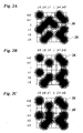
- Figure 2A shows an array of 6x6 pixels 26, which represents a portion of an image to be printed.
- the pixels 26 are arranged in lines i-3, i-2, i-1, i, i+1, i+2 and columns j-3, j-2, j-1, j. j+1 and j+2.
- Black pixels are indicated by dots 28 as printed with the ink jet printer shown in figure 1 . Since the ink droplet forming a dot 28 tends to spread on the recording medium (paper), the optical density of the dot decreases gradually from the center toward the periphery, and the lighter peripheral portions of the dot extend beyond the area of the pixel, so that neighbouring dots overlap.
- the image that has been shown in largely magnified scale in figure 2A would give the impression of a uniform grey area.
- Figure 2B shows the same image in the case that the nozzle needed for printing the line i is defective, so that the dots at the pixel positions (i, j-2) and (i, j) are missing. This would give rise to a perceptible brighter gap in the printed image at the position of the line i.
- the processing unit 24 shown in figure 1 performs a camouflage step which, in the given example, leads to the insertion of an additional dot 30 at the pixel position (i-1, j-1), i.e. in the pixel line i-1 directly adjacent to the defective line i.
- the image shown in Figure 2C resembles the ideal image shown in Figure 2A .
- the print data are supplied to the printer in a multi-level format, in which the grey value of each pixel is indicated by an 8-bit word, i.e. by an integral number between 0 and 255.
- the number 0 represents a white pixel and the number 255 a black pixel with maximum optical density.
- the print data are thus represented by a multi-level pixel matrix 32 as is schematically shown in figure 3 .
- each pixel line of this pixel matrix will be printed by only one of the nozzles 22 of the printhead.
- the printer may be equipped with a detection system which automatically detects and locates defective nozzles.
- the location of a defective nozzle may also be input by the user.
- the pixels in this line are non-printable pixels 34, whereas the other pixels 36, 38 and 40 are printable. Pixels 38 and 40 in the lines directly adjacent to the non-printable pixels 34 are shown in dark hatching.
- the non-printable pixels 34 and pixels 38 and 40 adjacent thereto form a camouflage area that is involved in camouflaging the effect of the defective nozzle.
- FIG. 4 illustrates a conventional error propagation scheme 42 (a Floyd Steinberg scheme) that is frequently used for this purpose.
- a number of arrows originate from a source pixel 44 and point to four target pixels 46 adjacent to the source pixel.
- the fractions (7/16, etc.) given in the target pixels 46 indicate the weight factors with which the error remaining from the source pixel is distributed over the target pixels.
- the theshold value th with which the grey level of the source pixel 44 is compared is 255, for example.
- This standard arrow propagation scheme will be used for the printable pixels 36 outside of the camouflage area.
- Figure 5 illustrates a modified error propagation scheme 48 that will be used for the pixels 38 in the line that is processed immediately before the line including the non-printable pixels 34.
- the error from the source pixel 44 is propagated with a weight factor of 1 (16/16) only to the next pixel in the same line.
- the theshold value th for the source pixel 44 is again 255.
- the large weight factor with which the error is propagated horizontally in figure 5 increases the likelihood that additional black pixels are added in this line, in order to achieve a camouflage effect similar to the one shown in figure 2C .
- Figure 6 shows another modified error propagation scheme 50 that will be used for the non-printable pixels 34 in figure 3 .
- the error from the (non-printable) target pixel 44 is propagated only into the line below, i.e. the line formed by the pixels 40 in figure 4 .
- the sum of the weight factors is again equal to 1, so that the error is fully transferred onto the neighbouring line.
- the threshold value for the non-printable pixels 34 is increased to a level above 255. In other words, even when the grey level of such a pixel is equal to 255, the pixel will nevertheless be made white and the error of 255 will be propagated to the line below.
- the image information of the line that cannot be printed because of the nozzle defect will be fully transferred to the line immediately therebelow. Again, this increases the likelihood that one of the pixels 40 in figure 3 will be made black in order to camouflage the nozzle defect.
- the pixels 40 form part of the camouflage area because they are affected by the error propagation scheme 50 shown in figure 6 . However, when the pixels 40 are themselves processed in the error diffusion process, the standard error propagation scheme 42 of figure 4 may be used.
- the threshold value utilised in the error diffusion process is either 255 (for the error propagation schemes 42 and 48) or infinity (for the scheme 50).
- the weight factors indicated in figure 6 are reduced correspondingly. This modified embodiment would have the effect that the likelihood of becoming black is increased for the pixels 38 (above the line of the nozzle defect) and decreased for the pixels 40 (the line below the nozzle defect).
- the target pixels 46 are not more than one line or column away from the source pixel 44.
- the maximum distance between source and target pixel may be larger, e. g. 2.
- the camouflage area would also include the first and the fifth line in Figure 3 .
- Figure 7 illustrates the case of a specific two-pass print mode.
- one of the two nozzles responsible for printing the third line in the pixel matrix 32 in figure 7 is defective, only every second pixel in this line will be a non-printable pixel 34, and the intervening pixels 52 will belong to the camouflage area.
- the pixel 52 will be treated with an error propagation scheme in which the error is only propagated downward but not horizontally.
- the error may be propagated horizontally (as in Figure 5 ) and/or downwardly.
- two different error propagations schemes have to be used, depending upon whether or not the pixel is located directly above a non-printable pixel 34.
- camouflage process described above is particularly efficient for images which mainly contain small or medium grey levels. In case of very dark images and, in the extreme, in the case of solid black areas, it is increasingly difficult or even impossible to add more black pixels in the camouflage area. Nevertheless, the camouflage process may be useful even for dark or black images, depending upon the design of the printer. Some known printers are capable of printing a plainly black area even when the percentage of black pixels in the bitmap is somewhat smaller than 100%. In this case, the modified error propagation schemes for the camouflage area may lead to an over-saturated bitmap which would still mask the nozzle defect to some extent.
- step S100 the multi-level pixel matrix 32 is established by reading-in the grey values of the pixels.
- the pixel lines that are affected by nozzle failures of the printhead are identified in step S101.
- step S102 the camouflage area is determined.
- An optional step S103 may involve a decrease of the threshold value th, e. g. from 255 to 191, for the lines (pixel 38 in Figure 3 ) preceding the lines affected by the defect.
- step S104 identifies the pixels (such as the pixels 34 and 38 in Figure 3 ) for which a modified error propagation scheme (50 or 48) has to be employed and selects the appropriate scheme.
- step S105 the error diffusion process is performed for all the pixels of the pixel matrix with either the non-modified or the selected one of the modified error propagation schemes.
- the resulting bitmap is then printed in step S106.
- the step S100 may be performed after the step S101 or even after the step S104.
- Figure 9 illustrates another embodiment which is adapted to the case that the print data are presented already in the format of a bitmap, i.e. a matrix of only black and white pixels.
- the bitmap is read in step S200.
- the steps S201 and S202 correspond to the steps S101 and S102 discussed above.
- step S203 the part of the bitmap which corresponds to the camouflage area is reconverted into a multi-level pixel matrix. To this end, a value of 255 is assigned to each of the black pixels of the pixel matrix, i.e. the pixels having the binary value 1, and the white 0-pixels are left as they are. All non-printable pixels 34 may be set to 0.
- the steps S204, S205 and S206 correspond again to the steps S104, S105 and S106, with the difference that steps S204 and S205 are performed only for the camouflage area and for the lines that contain the corresponding target pixels.
Landscapes
- Engineering & Computer Science (AREA)
- Quality & Reliability (AREA)
- Ink Jet (AREA)
- Facsimile Image Signal Circuits (AREA)
- Particle Formation And Scattering Control In Inkjet Printers (AREA)
Description
- The invention relates to a printing method for a printer having a printhead with a plurality of print elements and capable of printing a binary pixel image, the method comprising the steps of: locating defective print elements, determining a camouflage area in the vicinity of pixels that would have to be printed with the defective print elements, and camouflaging defective print elements by modifying image information in said camouflage area. The invention further relates to a printer and to a computer program implementing this method.
- The invention is applicable, for example, to an ink jet printer the printhead of which comprises a plurality of nozzles as print elements. Typically, the nozzles are arranged in a line that extends in parallel with the direction (subscanning direction) in which a recording medium, e.g. paper, is transported through the printer, and the printhead scans the paper in a direction (main scanning direction) perpendicular to the subscanning direction. A complete swath of the image is printed in a single pass of the printhead, and then the paper is transported by the width of the swath so as to print the next swath. When a nozzle of the printhead is defective, e.g. has become clogged, the corresponding pixel line is missing in the printed image, so that image information is lost and the quality of the print is degraded.
- A printer may also be operated in a multi-pass mode, in which only part of the image information of a swath is printed in a first pass and the missing pixels are filled-in during one or more subsequent passes of the printhead. In this case, it is sometimes possible that a defective nozzle is backed-up by a non-defective nozzle, though on the cost of productivity.
-
US-A-6 215 557 discloses a method of the type indicated above, wherein, when a nozzle is defective, the print data are altered so as to bypass the faulty nozzle. This means that a pixel that would have but cannot be printed with the defective nozzle is substituted by printing an extra pixel in one of the neighbouring lines that are printed with non-defective nozzles, so that the average optical density of the image area is conserved and the defect resulting from the nozzle failure is camouflaged and becomes almost imperceptible. This method involves a specific algorithm that operates on a bitmap, which represents the print data, and shifts each pixel that cannot be printed to a neighbouring pixel position. However, if this neighbouring pixel position happens to be occupied by a pixel already printed, anyway, pursuant to the original print data, then the extra pixel cannot be printed, and a loss of image information will nevertheless occur. -
EP-A-1157840 describes a method using tuned error diffusion tables to print a multi-level halftoned image. The error diffusion tables are based on a same error propagation scheme and a proportional relation between errors distributed to neighbouring pixels remains equal. - It is an object of the invention to provide a printing method in which the camouflage step can be performed more efficiently and is readily integrated in the workflow of the print process as disclosed in
claim 1. - According to the invention, the camouflaging step is incorporated in a halftoning step, in which error diffusion is used for creating said binary pixel image, and comprises a step of modifying an error propagation scheme for the camouflage area.
- The print data of an image to be printed is frequently supplied to the printer in the form of a multi-level pixel matrix, in which the grey level of each individual pixel may vary over a continuous or practically continous range. For example, the grey level of each pixel may be given by an 8-bit word, i.e. an integral number between 0 and 255, so that 256 different grey levels may be distinguished. However, since the printer is only capable of printing a binary image or bitmap, in which each pixel can only be either printed or not, it is necessary to perform a halftoning step in which the multi-level pixel matrix is transformed into a bitmap with conservation of the average grey level.
- A commonly employed halftoning method is an error diffusion process. In this process, the grey level of a pixel that is currently being processed is compared to a predetermined threshold value. When the grey level is larger than the threshold value, the corresponding pixel in the bitmap is made black, the threshold value is subtracted from the grey level, and the rest or error is diffused, i.e. propagated or distributed over a number of target pixels in the vicinity of the source pixel, i.e. the pixel that is being processed. When the grey level of the source pixel is smaller than the threshold value, the corresponding pixel in the bitmap is made white, and the error which is distributed over the target pixels in the like manner is then formed by the whole grey level of the source pixel. In order to distribute the error over the target pixels, the error is multiplied with a specific weight factor for each target pixel. This weight factor depends on the spatial relationship between the source pixel and the target pixel. The grey level of the target pixel is increased by the product of the error and the weight factor. When, later in the process, it is the turn of the target pixel to be processed, the grey level that is compared to the threshold value will thus be larger or smaller than the original grey level of the pixel as specified by the print data. The result of this process is a bitmap in which the average grey level of a small image area is approximately equal to the grey level of the same area in the original multi-level pixel matrix,
- An error diffusion process may be characterised by an error propagation scheme which specifies the threshold value to be employed, the selection of target pixels and their weight factors. If a pixel of the bitmap cannot be printed because the corresponding print element of the printer is defective, then, according to the invention, the error propagation scheme for this pixel and/or the pixels in the neighbourhood is modified in order to achieve at least one of the following two objectives: (1) increasing the likelihood that an error from a printable pixel is propagated onto other printable pixels rather than to a non-printable pixel, and (2) avoiding that a non-printable pixel is made black, and, instead, assuring that its image information is treated as an error and is at least partly propagated onto to printable pixels. The first objective can be achieved by increasing the weight factors assigned to printable target pixels. This will lead to the creation of more black pixels in the neighbourhood of the non-printable pixel, so that the image defect is camouflaged to some extent. The second objective can be achieved by increasing the threshold value for the non-printable pixels, possibly to infinity, and thereby increasing the error that is diffused onto neighbouring printable pixels. Again, the result is an increased number of black pixels in the vicinity of the non-printable pixel, and the image defect is camouflaged.
- It is a main advantage of the present invention that the camouflage procedure does not require an extra processing step but is incorporated in the error diffusion process which needs to be executed anyway in order to create the bitmap. It should be noted that the term "bitmap", as used here, does not mean that a bitmap must actually be stored physically in a storage medium, but only means that the print data are provided in binary form, so that each pixel is represented by a single bit. Thus, the "bitmap" may well be generated "on the fly" during the print process.
- The invention further has the advantage that the loss of image information caused by defective print elements can reliably be controlled or even eliminated completely by appropriately adapting the error propagation scheme. Another advantage is that the method can be carried out at a comparatively early stage in the processing sequence, so that the method can also be adapted, for example, to printer hardware which has no sufficient processing capability for carrying out corrections on bitmap level. It is even possible that the method according to the invention is executed in a host computer from which the print data are sent to the printer, provided that the information on the defective nozzles of the printer is made available at the host computer. Then, if the printer forms part of a multi-user network, the data processing necessary for carrying out the invention may be distributed over a plurality of computers in the network.
- Useful details and further developments of the invention are indicated in the dependent claims.
- The invention is particularly useful when the print data that are supplied to the printer are in the multi-level format. However, if these data are in the binary format already, it is a simple matter to reconvert these data into multi-level data, with or without averaging over clusters of adjacent pixels, and then to employ the method as described above.
- Preferably, the camouflage area, where a modified error propagation scheme applies, comprises both the source pixels for which a non-printable pixel is a target pixel, and the target pixels associated with the non-printable pixels. In order to prevent the error diffusion process from becoming recursive, it is common practice that the target pixels are limited to those pixels that are processed later than the respective source pixel. Thus, when the lines of the pixel matrix are processed in the order of increasing line index, and the pixels within each line are processed in the order of increasing column index, a target pixel will always have either a larger line index or a larger column index than the corresponding source pixel. Then, when printing in the single-pass mode, for example the camouflage area will be formed by one or more pixel lines adjacent to the line that is affected by the nozzle failure. For example, the camouflage area may then comprise the two direct neighbours of the line that cannot be printed.
- However, the invention is also applicable in multi-pass printing. Then, a nozzle failure will generally not have the effect that a complete line is missing in the printed image, but that, for example in the case of two-pass printing, typically only half the pixels in the line will be missing. In this case, the camouflage area may consist of the remaining, printable pixels in the line in which half of the pixels are missing. Optionally, the camouflage area may also be extended to the adjacent lines.
- When the weight factors assigned to printable target pixels sum up to 100%, the image information of the pixel will be conserved completely, except for those cases where the camouflage area becomes saturated with black pixels. In a modified embodiment, however, it is possible to use an error propagation scheme in which the sum of the weight factors of printable pixels is smaller than 100%, so that a certain loss of image information is admitted. To preserve the frequency of the image information more precise the threshold value to be employed for the printable pixels in the camouflage area can be decreased. This may have the effect that some of the black pixels that cannot be printed are "shifted" in rearward direction, i.e. in the direction of decreasing line and column indices.
- Preferred embodiments of the invention will now be explained in conjunction with the drawings, in which:
- Fig. 1
- is a schematic view of an ink jet printer to which the invention is applicable;
- Figs. 2A-C
- are diagrams of an area of 6x6 pixels of an image in various representations, illustrating the effect of a nozzle failure and the camouflage process;
- Fig. 3
- is a diagram of a 5x5-pixel matrix illustrating the construction of a camouflage area for a single-pass print mode;
- Fig. 4
- is a diagram illustrating a standard error propagation scheme;
- Figs. 5 and 6
- are diagrams illustrating modified error propagation schemes;
- Fig. 7
- is a diagram of a 5x5-pixel matrix illustrating the construction of a camouflage area for a specific two-pass print mode;
- Fig. 8
- is a flow diagram illustrating an embodiment of the method according to the invention;
- Fig. 9
- is a flow diagram for a modified embodiment of the invention; and
- Figs. 10A, B
- are diagrams of a bitmap and a pixel matrix illustrating the modified embodiment.
- As is shown in
figure 1 , an ink jet printer comprises aplaten 10 which serves for transporting arecording paper 12 in a subscanning direction (arrow A) past aprinthead unit 14. Theprinthead unit 14 is mounted on acarriage 16 that is guided onguide rails 18 and is movable back and forth in a main scanning direction (arrow B) relative to therecording paper 12. In the example shown, theprinthead unit 14 comprises fourprintheads 20, one for each of the basic colours cyan, magenta, yellow and black. Each printhead has a linear array ofnozzles 22 extending in the subscanning direction. Thenozzles 22 of theprintheads 20 can be energised individually to eject ink droplets onto therecording paper 12, thereby to print a pixel on the paper. When thecarriage 16 is moved in the direction B across the width of thepaper 12, a swath of an image can be printed. The number of pixel lines of the swath corresponds to the number ofnozzles 22 of each printhead. When thecarriage 16 has completed one pass, thepaper 12 is advanced by the width of the swath, so that the next swath can be printed. - The
printheads 20 are controlled by aprocessing unit 24 which processes the print data in a manner that will be described in detail hereinbelow. The discussion will be focused on printing in black colour, but is equivalently valid for printing in the other colours. -
Figure 2A shows an array of6x6 pixels 26, which represents a portion of an image to be printed. Thepixels 26 are arranged in lines i-3, i-2, i-1, i, i+1, i+2 and columns j-3, j-2, j-1, j. j+1 and j+2. Black pixels are indicated bydots 28 as printed with the ink jet printer shown infigure 1 . Since the ink droplet forming adot 28 tends to spread on the recording medium (paper), the optical density of the dot decreases gradually from the center toward the periphery, and the lighter peripheral portions of the dot extend beyond the area of the pixel, so that neighbouring dots overlap. The image that has been shown in largely magnified scale infigure 2A would give the impression of a uniform grey area. -
Figure 2B shows the same image in the case that the nozzle needed for printing the line i is defective, so that the dots at the pixel positions (i, j-2) and (i, j) are missing. This would give rise to a perceptible brighter gap in the printed image at the position of the line i. - In order to eliminate or at least mitigate this image defect, the
processing unit 24 shown infigure 1 performs a camouflage step which, in the given example, leads to the insertion of anadditional dot 30 at the pixel position (i-1, j-1), i.e. in the pixel line i-1 directly adjacent to the defective line i. As a result, on the macroscopic scale the image shown inFigure 2C resembles the ideal image shown inFigure 2A . - This camouflage process will now be explained in detail. At first, it shall be assumed that the print data are supplied to the printer in a multi-level format, in which the grey value of each pixel is indicated by an 8-bit word, i.e. by an integral number between 0 and 255. The
number 0 represents a white pixel and the number 255 a black pixel with maximum optical density. The print data are thus represented by amulti-level pixel matrix 32 as is schematically shown infigure 3 . In the single-pass mode, each pixel line of this pixel matrix will be printed by only one of thenozzles 22 of the printhead. The printer may be equipped with a detection system which automatically detects and locates defective nozzles. As an alternative, the location of a defective nozzle may also be input by the user. When, for example, the nozzle responsible for printing the third line of the pixel matrix is defective, the pixels in this line arenon-printable pixels 34, whereas theother pixels Pixels non-printable pixels 34 are shown in dark hatching. Thenon-printable pixels 34 andpixels - An error propagation halftoning step is used for transforming the
multi-level pixel matrix 32 into a bitmap.Figure 4 illustrates a conventional error propagation scheme 42 (a Floyd Steinberg scheme) that is frequently used for this purpose. As is shown infigure 4 , a number of arrows originate from asource pixel 44 and point to fourtarget pixels 46 adjacent to the source pixel. The fractions (7/16, etc.) given in thetarget pixels 46 indicate the weight factors with which the error remaining from the source pixel is distributed over the target pixels. the theshold value th with which the grey level of thesource pixel 44 is compared is 255, for example. This standard arrow propagation scheme will be used for theprintable pixels 36 outside of the camouflage area. - It is assumed here that the processing of the source pixels proceeds from left to right and from top to bottom. As is indicated by the arrows, the error is propagated only in "forward" direction, i.e. each source pixel is processed earlier than its target pixels.
-
Figure 5 illustrates a modifiederror propagation scheme 48 that will be used for thepixels 38 in the line that is processed immediately before the line including thenon-printable pixels 34. Here, the error from thesource pixel 44 is propagated with a weight factor of 1 (16/16) only to the next pixel in the same line. Thus, the image information is kept in the line in which it can actually be printed, and thenon-printable pixels 34 in the line below are not used as target pixels. The theshold value th for thesource pixel 44 is again 255. The large weight factor with which the error is propagated horizontally infigure 5 increases the likelihood that additional black pixels are added in this line, in order to achieve a camouflage effect similar to the one shown infigure 2C . -
Figure 6 shows another modifiederror propagation scheme 50 that will be used for thenon-printable pixels 34 infigure 3 . Here, the error from the (non-printable)target pixel 44 is propagated only into the line below, i.e. the line formed by thepixels 40 infigure 4 . The sum of the weight factors is again equal to 1, so that the error is fully transferred onto the neighbouring line. Moreover, in this scheme, the threshold value for thenon-printable pixels 34 is increased to a level above 255. In other words, even when the grey level of such a pixel is equal to 255, the pixel will nevertheless be made white and the error of 255 will be propagated to the line below. Thus, the image information of the line that cannot be printed because of the nozzle defect will be fully transferred to the line immediately therebelow. Again, this increases the likelihood that one of thepixels 40 infigure 3 will be made black in order to camouflage the nozzle defect. Thepixels 40 form part of the camouflage area because they are affected by theerror propagation scheme 50 shown infigure 6 . However, when thepixels 40 are themselves processed in the error diffusion process, the standarderror propagation scheme 42 offigure 4 may be used. - In the example given above, it has been assumed that the threshold value utilised in the error diffusion process is either 255 (for the
error propagation schemes 42 and 48) or infinity (for the scheme 50). In a modified embodiment, however, it would be possible to use a somewhat lower threshold value for thepixels 38 and/or 40, in order to further increase the likelihood of black pixels being created. Optionally, in order to avoid an over-compensation, it is possible that the weight factors indicated infigure 6 are reduced correspondingly. This modified embodiment would have the effect that the likelihood of becoming black is increased for the pixels 38 (above the line of the nozzle defect) and decreased for the pixels 40 (the line below the nozzle defect). - With the error propagation schemes of
Figures 4 to 6 , thetarget pixels 46 are not more than one line or column away from thesource pixel 44. In a modified scheme, the maximum distance between source and target pixel may be larger, e. g. 2. Then, the camouflage area would also include the first and the fifth line inFigure 3 . -
Figure 7 illustrates the case of a specific two-pass print mode. When one of the two nozzles responsible for printing the third line in thepixel matrix 32 infigure 7 is defective, only every second pixel in this line will be anon-printable pixel 34, and the interveningpixels 52 will belong to the camouflage area. In the error diffusion process, thepixel 52 will be treated with an error propagation scheme in which the error is only propagated downward but not horizontally. For thenon-printable pixels 34 the error may be propagated horizontally (as inFigure 5 ) and/or downwardly. In case of thepixels 38, two different error propagations schemes have to be used, depending upon whether or not the pixel is located directly above anon-printable pixel 34. - The camouflage process described above is particularly efficient for images which mainly contain small or medium grey levels. In case of very dark images and, in the extreme, in the case of solid black areas, it is increasingly difficult or even impossible to add more black pixels in the camouflage area. Nevertheless, the camouflage process may be useful even for dark or black images, depending upon the design of the printer. Some known printers are capable of printing a plainly black area even when the percentage of black pixels in the bitmap is somewhat smaller than 100%. In this case, the modified error propagation schemes for the camouflage area may lead to an over-saturated bitmap which would still mask the nozzle defect to some extent.
- A specific embodiment of the method according to the invention will now be described by reference to the flow diagram shown in
figure 8 . In step S100 themulti-level pixel matrix 32 is established by reading-in the grey values of the pixels. The pixel lines that are affected by nozzle failures of the printhead are identified in step S101. Then, in step S102, the camouflage area is determined. An optional step S103 may involve a decrease of the threshold value th, e. g. from 255 to 191, for the lines (pixel 38 inFigure 3 ) preceding the lines affected by the defect. Step S104 identifies the pixels (such as thepixels Figure 3 ) for which a modified error propagation scheme (50 or 48) has to be employed and selects the appropriate scheme. In step S105, the error diffusion process is performed for all the pixels of the pixel matrix with either the non-modified or the selected one of the modified error propagation schemes. The resulting bitmap is then printed in step S106. - Alternatively, the step S100 may be performed after the step S101 or even after the step S104.
-
Figure 9 illustrates another embodiment which is adapted to the case that the print data are presented already in the format of a bitmap, i.e. a matrix of only black and white pixels. The bitmap is read in step S200. The steps S201 and S202 correspond to the steps S101 and S102 discussed above. In step S203 the part of the bitmap which corresponds to the camouflage area is reconverted into a multi-level pixel matrix. To this end, a value of 255 is assigned to each of the black pixels of the pixel matrix, i.e. the pixels having thebinary value 1, and the white 0-pixels are left as they are. Allnon-printable pixels 34 may be set to 0. The steps S204, S205 and S206 correspond again to the steps S104, S105 and S106, with the difference that steps S204 and S205 are performed only for the camouflage area and for the lines that contain the corresponding target pixels. -
Figure 10A shows an example of the bitmap read in step S200. Again, it is assumed that the nozzle that is responsible for printing the pixels in line i in the single-pass mode is defective.Figure 10B illustrates the corresponding multi-level pixel matrix obtained in step S203. - The embodiment of
Figure 9 has been exemplified for the single-pass mode, but it goes without saying that this method is also applicable to a multi-pass mode, as has been described in conjunction withFigure 7 .
Claims (11)
- Printing method for a printer having a printhead (20) with a plurality of print elements (22) and capable of printing a binary pixel image, the method comprising the steps of:a) locating defective print elements,b) determining a camouflage area (34, 38, 40; 52) in the vicinity of pixels (34) that would have to be printed with the defective print elements, andc) camouflaging defective print elements by modifying image information in said camouflage area,characterised in that the camouflaging step is incorporated in a halftoning step, in which error diffusion is used for creating said binary pixel image, and comprises a step (S104; S204) of applying error diffusion by a first error propagation scheme (42) outside the camouflaging area and applying the error diffusion by a second error propagation scheme (48, 50) within the camouflage area different from the first error propagation scheme.
- The method of claim 1, wherein the error propagation scheme (48, 50) is modified such that the error is propagated with an increased weight factor to printable pixels (38, 40) in the camouflage area and with a reduced weight factor or not at all to non-printable pixels (34).
- The method of claim 2, wherein the sum of the weight factors with which the error is propagated to printable pixels (38, 40; 52) is equal to 1.
- The method of claim 2 or 3, wherein different error diffusion thresholds (th) are used inside and outside of the camouflage area.
- The method of any of the preceding claims, wherein the image information of non-printable pixels (34) is always treated as an error and is propagated to printable pixels (38, 40; 52).
- The method of any of the preceding claims, wherein a single-pass print mode is employed, a first modified error propagation scheme (48) is used for pixels (38) in a line that is processed immediately before a line of non-printable pixels (34), said first modified error propagation scheme (48) being adapted to propagate the error only within the same line.
- The method of one of the claims 1-5, wherein a multi-pass print mode is employed, a first modified error propagation scheme (48) is used for pixels (38) in a line that is processed immediately before a line of non-printable pixels (34), said first modified error propagation scheme (48) being adapted to propagate the error only within the same line or in pixels in a next line that are printed with non-defective nozzles.
- The method of one of the claims 1-5, wherein a single-pass print mode is employed, and a second modified error propagation scheme is used for the non-printable pixels (34), said second modified propagation scheme being arranged such that the error is propagated only onto pixels (40) in the same line but printed by non-defective nozzle's in the subsequent line or in a line subsequent to the line of non-printable pixels.
- The method of any of the preceding claims, wherein print data are received in the form of a first binary pixel image and are converted into a multi-level pixel matrix before the halftoning and camouflaging steps (204, 205) are carried out.
- A printer capable of printing a binary pixel image, characterised by a processing unit (24) in which a method of one of the claims 1 to 9 is implemented.
- A computer program comprising computer program code to make a processing unit (24), which forms part of or is connectable to a printer, execute the method according to one of the claims 1 to 8.
Priority Applications (1)
| Application Number | Priority Date | Filing Date | Title |
|---|---|---|---|
| EP20050103216 EP1593516B1 (en) | 2004-05-06 | 2005-04-21 | Printing method with camouflage of defective print elements |
Applications Claiming Priority (3)
| Application Number | Priority Date | Filing Date | Title |
|---|---|---|---|
| EP04076347 | 2004-05-06 | ||
| EP04076347 | 2004-05-06 | ||
| EP20050103216 EP1593516B1 (en) | 2004-05-06 | 2005-04-21 | Printing method with camouflage of defective print elements |
Publications (3)
| Publication Number | Publication Date |
|---|---|
| EP1593516A2 EP1593516A2 (en) | 2005-11-09 |
| EP1593516A3 EP1593516A3 (en) | 2009-12-23 |
| EP1593516B1 true EP1593516B1 (en) | 2012-08-29 |
Family
ID=35445892
Family Applications (1)
| Application Number | Title | Priority Date | Filing Date |
|---|---|---|---|
| EP20050103216 Expired - Lifetime EP1593516B1 (en) | 2004-05-06 | 2005-04-21 | Printing method with camouflage of defective print elements |
Country Status (1)
| Country | Link |
|---|---|
| EP (1) | EP1593516B1 (en) |
Cited By (1)
| Publication number | Priority date | Publication date | Assignee | Title |
|---|---|---|---|---|
| EP3205507A1 (en) | 2015-12-01 | 2017-08-16 | OCE-Technologies B.V. | Method of controlling a digital printer with failure compensation |
Families Citing this family (1)
| Publication number | Priority date | Publication date | Assignee | Title |
|---|---|---|---|---|
| CN109624538B (en) * | 2018-12-19 | 2021-11-23 | 合肥京东方卓印科技有限公司 | Method and device for printing ink, computer storage medium and terminal |
Family Cites Families (4)
| Publication number | Priority date | Publication date | Assignee | Title |
|---|---|---|---|---|
| US6215557B1 (en) | 1999-07-01 | 2001-04-10 | Lexmark International, Inc. | Entry of missing nozzle information in an ink jet printer |
| AUPQ766300A0 (en) * | 2000-05-22 | 2000-06-15 | Canon Kabushiki Kaisha | Defective nozzle compensation |
| US6612678B2 (en) * | 2000-09-04 | 2003-09-02 | Canon Kabushiki Kaisha | Ink jet printing system and method |
| US20040174570A1 (en) * | 2002-12-02 | 2004-09-09 | Plunkett Richard Thomas | Variable size dither matrix usage |
-
2005
- 2005-04-21 EP EP20050103216 patent/EP1593516B1/en not_active Expired - Lifetime
Cited By (1)
| Publication number | Priority date | Publication date | Assignee | Title |
|---|---|---|---|---|
| EP3205507A1 (en) | 2015-12-01 | 2017-08-16 | OCE-Technologies B.V. | Method of controlling a digital printer with failure compensation |
Also Published As
| Publication number | Publication date |
|---|---|
| EP1593516A3 (en) | 2009-12-23 |
| EP1593516A2 (en) | 2005-11-09 |
Similar Documents
| Publication | Publication Date | Title |
|---|---|---|
| EP1529644B1 (en) | Method of camouflaging defective print elements in a printer | |
| JP4164305B2 (en) | Inkjet recording method and inkjet recording apparatus | |
| EP1157840B1 (en) | Defective nozzle compensation | |
| US7903290B2 (en) | Printing method with camouflage of defective print elements | |
| CN1326699C (en) | Ink jet print apparatus and ink jet print method | |
| US7265770B2 (en) | Method of camouflaging defective print elements in a printer | |
| WO2007100476A2 (en) | Multi-level printing masking method | |
| EP2842750B1 (en) | Image processing method, image processing device, image forming device, and inkjet recording device | |
| US9434176B1 (en) | Vector compensation for inoperative ink-jets in composite colors | |
| JP4385626B2 (en) | Image processing apparatus, image processing method, and image processing program | |
| JP2010012625A (en) | Inkjet recording device and control method and program therefor | |
| US7185964B2 (en) | Printing method and printing apparatus | |
| EP1634709A1 (en) | Printing method with camouflage of defective print elements | |
| EP1593516B1 (en) | Printing method with camouflage of defective print elements | |
| JP2006115431A (en) | Intermediate gradation processing apparatus, printing apparatus, information processing apparatus, intermediate gradation processing method, and program | |
| EP1536371B1 (en) | Method of camouflaging defects of printing elements in a printer | |
| JP5247623B2 (en) | Inkjet recording apparatus and inkjet recording method | |
| EP2616245B1 (en) | Method of camouflaging artefacts in high coverage areas in images to be printed | |
| JP2006103054A (en) | Recording method and recording apparatus | |
| JP2008093982A (en) | Ink jet recording apparatus and recording control method | |
| JP5288918B2 (en) | Image forming apparatus, control method therefor, and program | |
| JP2004306552A (en) | Image recording method and image recorder | |
| JP4314100B2 (en) | Inkjet recording method and inkjet recording apparatus | |
| JP2006062088A (en) | Inkjet printer device | |
| JP2019166835A (en) | Recording device, recording method and recording system |
Legal Events
| Date | Code | Title | Description |
|---|---|---|---|
| PUAI | Public reference made under article 153(3) epc to a published international application that has entered the european phase |
Free format text: ORIGINAL CODE: 0009012 |
|
| AK | Designated contracting states |
Kind code of ref document: A2 Designated state(s): AT BE BG CH CY CZ DE DK EE ES FI FR GB GR HU IE IS IT LI LT LU MC NL PL PT RO SE SI SK TR |
|
| AX | Request for extension of the european patent |
Extension state: AL BA HR LV MK YU |
|
| PUAL | Search report despatched |
Free format text: ORIGINAL CODE: 0009013 |
|
| AK | Designated contracting states |
Kind code of ref document: A3 Designated state(s): AT BE BG CH CY CZ DE DK EE ES FI FR GB GR HU IE IS IT LI LT LU MC NL PL PT RO SE SI SK TR |
|
| AX | Request for extension of the european patent |
Extension state: AL BA HR LV MK YU |
|
| 17P | Request for examination filed |
Effective date: 20100623 |
|
| AKX | Designation fees paid |
Designated state(s): AT BE BG CH CY CZ DE DK EE ES FI FR GB GR HU IE IS IT LI LT LU MC NL PL PT RO SE SI SK TR |
|
| 17Q | First examination report despatched |
Effective date: 20110203 |
|
| GRAP | Despatch of communication of intention to grant a patent |
Free format text: ORIGINAL CODE: EPIDOSNIGR1 |
|
| GRAS | Grant fee paid |
Free format text: ORIGINAL CODE: EPIDOSNIGR3 |
|
| GRAA | (expected) grant |
Free format text: ORIGINAL CODE: 0009210 |
|
| AK | Designated contracting states |
Kind code of ref document: B1 Designated state(s): AT BE BG CH CY CZ DE DK EE ES FI FR GB GR HU IE IS IT LI LT LU MC NL PL PT RO SE SI SK TR |
|
| REG | Reference to a national code |
Ref country code: GB Ref legal event code: FG4D |
|
| REG | Reference to a national code |
Ref country code: CH Ref legal event code: EP |
|
| REG | Reference to a national code |
Ref country code: AT Ref legal event code: REF Ref document number: 572843 Country of ref document: AT Kind code of ref document: T Effective date: 20120915 |
|
| REG | Reference to a national code |
Ref country code: IE Ref legal event code: FG4D |
|
| REG | Reference to a national code |
Ref country code: DE Ref legal event code: R096 Ref document number: 602005035853 Country of ref document: DE Effective date: 20121025 |
|
| REG | Reference to a national code |
Ref country code: NL Ref legal event code: T3 |
|
| REG | Reference to a national code |
Ref country code: AT Ref legal event code: MK05 Ref document number: 572843 Country of ref document: AT Kind code of ref document: T Effective date: 20120829 |
|
| REG | Reference to a national code |
Ref country code: LT Ref legal event code: MG4D Effective date: 20120829 |
|
| PG25 | Lapsed in a contracting state [announced via postgrant information from national office to epo] |
Ref country code: FI Free format text: LAPSE BECAUSE OF FAILURE TO SUBMIT A TRANSLATION OF THE DESCRIPTION OR TO PAY THE FEE WITHIN THE PRESCRIBED TIME-LIMIT Effective date: 20120829 Ref country code: CY Free format text: LAPSE BECAUSE OF FAILURE TO SUBMIT A TRANSLATION OF THE DESCRIPTION OR TO PAY THE FEE WITHIN THE PRESCRIBED TIME-LIMIT Effective date: 20120829 Ref country code: IS Free format text: LAPSE BECAUSE OF FAILURE TO SUBMIT A TRANSLATION OF THE DESCRIPTION OR TO PAY THE FEE WITHIN THE PRESCRIBED TIME-LIMIT Effective date: 20121229 Ref country code: LT Free format text: LAPSE BECAUSE OF FAILURE TO SUBMIT A TRANSLATION OF THE DESCRIPTION OR TO PAY THE FEE WITHIN THE PRESCRIBED TIME-LIMIT Effective date: 20120829 Ref country code: AT Free format text: LAPSE BECAUSE OF FAILURE TO SUBMIT A TRANSLATION OF THE DESCRIPTION OR TO PAY THE FEE WITHIN THE PRESCRIBED TIME-LIMIT Effective date: 20120829 |
|
| PG25 | Lapsed in a contracting state [announced via postgrant information from national office to epo] |
Ref country code: GR Free format text: LAPSE BECAUSE OF FAILURE TO SUBMIT A TRANSLATION OF THE DESCRIPTION OR TO PAY THE FEE WITHIN THE PRESCRIBED TIME-LIMIT Effective date: 20121130 Ref country code: SE Free format text: LAPSE BECAUSE OF FAILURE TO SUBMIT A TRANSLATION OF THE DESCRIPTION OR TO PAY THE FEE WITHIN THE PRESCRIBED TIME-LIMIT Effective date: 20120829 Ref country code: PT Free format text: LAPSE BECAUSE OF FAILURE TO SUBMIT A TRANSLATION OF THE DESCRIPTION OR TO PAY THE FEE WITHIN THE PRESCRIBED TIME-LIMIT Effective date: 20121231 Ref country code: SI Free format text: LAPSE BECAUSE OF FAILURE TO SUBMIT A TRANSLATION OF THE DESCRIPTION OR TO PAY THE FEE WITHIN THE PRESCRIBED TIME-LIMIT Effective date: 20120829 Ref country code: BE Free format text: LAPSE BECAUSE OF FAILURE TO SUBMIT A TRANSLATION OF THE DESCRIPTION OR TO PAY THE FEE WITHIN THE PRESCRIBED TIME-LIMIT Effective date: 20120829 |
|
| PG25 | Lapsed in a contracting state [announced via postgrant information from national office to epo] |
Ref country code: RO Free format text: LAPSE BECAUSE OF FAILURE TO SUBMIT A TRANSLATION OF THE DESCRIPTION OR TO PAY THE FEE WITHIN THE PRESCRIBED TIME-LIMIT Effective date: 20120829 Ref country code: EE Free format text: LAPSE BECAUSE OF FAILURE TO SUBMIT A TRANSLATION OF THE DESCRIPTION OR TO PAY THE FEE WITHIN THE PRESCRIBED TIME-LIMIT Effective date: 20120829 Ref country code: CZ Free format text: LAPSE BECAUSE OF FAILURE TO SUBMIT A TRANSLATION OF THE DESCRIPTION OR TO PAY THE FEE WITHIN THE PRESCRIBED TIME-LIMIT Effective date: 20120829 Ref country code: DK Free format text: LAPSE BECAUSE OF FAILURE TO SUBMIT A TRANSLATION OF THE DESCRIPTION OR TO PAY THE FEE WITHIN THE PRESCRIBED TIME-LIMIT Effective date: 20120829 Ref country code: ES Free format text: LAPSE BECAUSE OF FAILURE TO SUBMIT A TRANSLATION OF THE DESCRIPTION OR TO PAY THE FEE WITHIN THE PRESCRIBED TIME-LIMIT Effective date: 20121210 |
|
| PG25 | Lapsed in a contracting state [announced via postgrant information from national office to epo] |
Ref country code: IT Free format text: LAPSE BECAUSE OF FAILURE TO SUBMIT A TRANSLATION OF THE DESCRIPTION OR TO PAY THE FEE WITHIN THE PRESCRIBED TIME-LIMIT Effective date: 20120829 Ref country code: PL Free format text: LAPSE BECAUSE OF FAILURE TO SUBMIT A TRANSLATION OF THE DESCRIPTION OR TO PAY THE FEE WITHIN THE PRESCRIBED TIME-LIMIT Effective date: 20120829 Ref country code: SK Free format text: LAPSE BECAUSE OF FAILURE TO SUBMIT A TRANSLATION OF THE DESCRIPTION OR TO PAY THE FEE WITHIN THE PRESCRIBED TIME-LIMIT Effective date: 20120829 |
|
| PLBE | No opposition filed within time limit |
Free format text: ORIGINAL CODE: 0009261 |
|
| STAA | Information on the status of an ep patent application or granted ep patent |
Free format text: STATUS: NO OPPOSITION FILED WITHIN TIME LIMIT |
|
| PG25 | Lapsed in a contracting state [announced via postgrant information from national office to epo] |
Ref country code: BG Free format text: LAPSE BECAUSE OF FAILURE TO SUBMIT A TRANSLATION OF THE DESCRIPTION OR TO PAY THE FEE WITHIN THE PRESCRIBED TIME-LIMIT Effective date: 20121129 |
|
| 26N | No opposition filed |
Effective date: 20130530 |
|
| REG | Reference to a national code |
Ref country code: DE Ref legal event code: R097 Ref document number: 602005035853 Country of ref document: DE Effective date: 20130530 |
|
| PG25 | Lapsed in a contracting state [announced via postgrant information from national office to epo] |
Ref country code: MC Free format text: LAPSE BECAUSE OF FAILURE TO SUBMIT A TRANSLATION OF THE DESCRIPTION OR TO PAY THE FEE WITHIN THE PRESCRIBED TIME-LIMIT Effective date: 20120829 |
|
| REG | Reference to a national code |
Ref country code: CH Ref legal event code: PL |
|
| REG | Reference to a national code |
Ref country code: IE Ref legal event code: MM4A |
|
| PG25 | Lapsed in a contracting state [announced via postgrant information from national office to epo] |
Ref country code: CH Free format text: LAPSE BECAUSE OF NON-PAYMENT OF DUE FEES Effective date: 20130430 Ref country code: LI Free format text: LAPSE BECAUSE OF NON-PAYMENT OF DUE FEES Effective date: 20130430 |
|
| PG25 | Lapsed in a contracting state [announced via postgrant information from national office to epo] |
Ref country code: IE Free format text: LAPSE BECAUSE OF NON-PAYMENT OF DUE FEES Effective date: 20130421 |
|
| PG25 | Lapsed in a contracting state [announced via postgrant information from national office to epo] |
Ref country code: TR Free format text: LAPSE BECAUSE OF FAILURE TO SUBMIT A TRANSLATION OF THE DESCRIPTION OR TO PAY THE FEE WITHIN THE PRESCRIBED TIME-LIMIT Effective date: 20120829 |
|
| PG25 | Lapsed in a contracting state [announced via postgrant information from national office to epo] |
Ref country code: LU Free format text: LAPSE BECAUSE OF NON-PAYMENT OF DUE FEES Effective date: 20130421 Ref country code: HU Free format text: LAPSE BECAUSE OF FAILURE TO SUBMIT A TRANSLATION OF THE DESCRIPTION OR TO PAY THE FEE WITHIN THE PRESCRIBED TIME-LIMIT; INVALID AB INITIO Effective date: 20050421 |
|
| REG | Reference to a national code |
Ref country code: FR Ref legal event code: PLFP Year of fee payment: 12 |
|
| REG | Reference to a national code |
Ref country code: FR Ref legal event code: PLFP Year of fee payment: 13 |
|
| PGFP | Annual fee paid to national office [announced via postgrant information from national office to epo] |
Ref country code: NL Payment date: 20170420 Year of fee payment: 13 |
|
| PGFP | Annual fee paid to national office [announced via postgrant information from national office to epo] |
Ref country code: DE Payment date: 20170419 Year of fee payment: 13 Ref country code: FR Payment date: 20170419 Year of fee payment: 13 Ref country code: GB Payment date: 20170419 Year of fee payment: 13 |
|
| REG | Reference to a national code |
Ref country code: DE Ref legal event code: R119 Ref document number: 602005035853 Country of ref document: DE |
|
| REG | Reference to a national code |
Ref country code: NL Ref legal event code: MM Effective date: 20180501 |
|
| GBPC | Gb: european patent ceased through non-payment of renewal fee |
Effective date: 20180421 |
|
| PG25 | Lapsed in a contracting state [announced via postgrant information from national office to epo] |
Ref country code: NL Free format text: LAPSE BECAUSE OF NON-PAYMENT OF DUE FEES Effective date: 20180501 Ref country code: DE Free format text: LAPSE BECAUSE OF NON-PAYMENT OF DUE FEES Effective date: 20181101 |
|
| PG25 | Lapsed in a contracting state [announced via postgrant information from national office to epo] |
Ref country code: GB Free format text: LAPSE BECAUSE OF NON-PAYMENT OF DUE FEES Effective date: 20180421 |
|
| PG25 | Lapsed in a contracting state [announced via postgrant information from national office to epo] |
Ref country code: FR Free format text: LAPSE BECAUSE OF NON-PAYMENT OF DUE FEES Effective date: 20180430 |