EP1593453A1 - Gegenmesser und Herstellungsverfahren - Google Patents
Gegenmesser und Herstellungsverfahren Download PDFInfo
- Publication number
- EP1593453A1 EP1593453A1 EP05250076A EP05250076A EP1593453A1 EP 1593453 A1 EP1593453 A1 EP 1593453A1 EP 05250076 A EP05250076 A EP 05250076A EP 05250076 A EP05250076 A EP 05250076A EP 1593453 A1 EP1593453 A1 EP 1593453A1
- Authority
- EP
- European Patent Office
- Prior art keywords
- bed knife
- bed
- reel
- knife
- spring steel
- Prior art date
- Legal status (The legal status is an assumption and is not a legal conclusion. Google has not performed a legal analysis and makes no representation as to the accuracy of the status listed.)
- Withdrawn
Links
- 238000000034 method Methods 0.000 title claims abstract description 20
- 229910000639 Spring steel Inorganic materials 0.000 claims abstract description 30
- 238000005520 cutting process Methods 0.000 claims abstract description 28
- 238000004519 manufacturing process Methods 0.000 claims abstract description 19
- 238000000227 grinding Methods 0.000 claims abstract description 14
- 238000005452 bending Methods 0.000 claims abstract description 8
- 238000007493 shaping process Methods 0.000 claims abstract description 7
- 230000000712 assembly Effects 0.000 description 7
- 238000000429 assembly Methods 0.000 description 7
- 230000008569 process Effects 0.000 description 5
- 229910000975 Carbon steel Inorganic materials 0.000 description 4
- 239000010962 carbon steel Substances 0.000 description 4
- 230000006378 damage Effects 0.000 description 4
- 244000025254 Cannabis sativa Species 0.000 description 3
- 230000008901 benefit Effects 0.000 description 3
- 238000010438 heat treatment Methods 0.000 description 3
- 230000004044 response Effects 0.000 description 3
- 239000004575 stone Substances 0.000 description 3
- 229910000831 Steel Inorganic materials 0.000 description 2
- 230000009471 action Effects 0.000 description 2
- 238000012423 maintenance Methods 0.000 description 2
- 230000007246 mechanism Effects 0.000 description 2
- 239000010959 steel Substances 0.000 description 2
- WLWKHFQGISDXFN-UHFFFAOYSA-N C1C2=CCC=C1C=C2 Chemical compound C1C2=CCC=C1C=C2 WLWKHFQGISDXFN-UHFFFAOYSA-N 0.000 description 1
- 230000009286 beneficial effect Effects 0.000 description 1
- 230000008859 change Effects 0.000 description 1
- 238000010276 construction Methods 0.000 description 1
- 230000009849 deactivation Effects 0.000 description 1
- 230000001419 dependent effect Effects 0.000 description 1
- 230000000694 effects Effects 0.000 description 1
- 238000009434 installation Methods 0.000 description 1
- 238000003801 milling Methods 0.000 description 1
- 230000004048 modification Effects 0.000 description 1
- 238000012986 modification Methods 0.000 description 1
- 238000003825 pressing Methods 0.000 description 1
- 230000002035 prolonged effect Effects 0.000 description 1
- 230000008439 repair process Effects 0.000 description 1
- 239000011435 rock Substances 0.000 description 1
- 230000009528 severe injury Effects 0.000 description 1
- 238000010008 shearing Methods 0.000 description 1
- 230000007704 transition Effects 0.000 description 1
Images




Classifications
-
- A—HUMAN NECESSITIES
- A01—AGRICULTURE; FORESTRY; ANIMAL HUSBANDRY; HUNTING; TRAPPING; FISHING
- A01D—HARVESTING; MOWING
- A01D34/00—Mowers; Mowing apparatus of harvesters
- A01D34/01—Mowers; Mowing apparatus of harvesters characterised by features relating to the type of cutting apparatus
- A01D34/412—Mowers; Mowing apparatus of harvesters characterised by features relating to the type of cutting apparatus having rotating cutters
- A01D34/42—Mowers; Mowing apparatus of harvesters characterised by features relating to the type of cutting apparatus having rotating cutters having cutters rotating about a horizontal axis, e.g. cutting-cylinders
- A01D34/46—Mowers; Mowing apparatus of harvesters characterised by features relating to the type of cutting apparatus having rotating cutters having cutters rotating about a horizontal axis, e.g. cutting-cylinders hand-guided by a walking operator
- A01D34/47—Mowers; Mowing apparatus of harvesters characterised by features relating to the type of cutting apparatus having rotating cutters having cutters rotating about a horizontal axis, e.g. cutting-cylinders hand-guided by a walking operator with motor driven cutters or wheels
-
- B—PERFORMING OPERATIONS; TRANSPORTING
- B23—MACHINE TOOLS; METAL-WORKING NOT OTHERWISE PROVIDED FOR
- B23P—METAL-WORKING NOT OTHERWISE PROVIDED FOR; COMBINED OPERATIONS; UNIVERSAL MACHINE TOOLS
- B23P15/00—Making specific metal objects by operations not covered by a single other subclass or a group in this subclass
- B23P15/28—Making specific metal objects by operations not covered by a single other subclass or a group in this subclass cutting tools
- B23P15/40—Making specific metal objects by operations not covered by a single other subclass or a group in this subclass cutting tools shearing tools
-
- A—HUMAN NECESSITIES
- A01—AGRICULTURE; FORESTRY; ANIMAL HUSBANDRY; HUNTING; TRAPPING; FISHING
- A01D—HARVESTING; MOWING
- A01D34/00—Mowers; Mowing apparatus of harvesters
- A01D34/01—Mowers; Mowing apparatus of harvesters characterised by features relating to the type of cutting apparatus
- A01D34/412—Mowers; Mowing apparatus of harvesters characterised by features relating to the type of cutting apparatus having rotating cutters
- A01D34/42—Mowers; Mowing apparatus of harvesters characterised by features relating to the type of cutting apparatus having rotating cutters having cutters rotating about a horizontal axis, e.g. cutting-cylinders
- A01D34/52—Cutting apparatus
-
- A—HUMAN NECESSITIES
- A01—AGRICULTURE; FORESTRY; ANIMAL HUSBANDRY; HUNTING; TRAPPING; FISHING
- A01D—HARVESTING; MOWING
- A01D34/00—Mowers; Mowing apparatus of harvesters
- A01D34/01—Mowers; Mowing apparatus of harvesters characterised by features relating to the type of cutting apparatus
- A01D34/412—Mowers; Mowing apparatus of harvesters characterised by features relating to the type of cutting apparatus having rotating cutters
- A01D34/42—Mowers; Mowing apparatus of harvesters characterised by features relating to the type of cutting apparatus having rotating cutters having cutters rotating about a horizontal axis, e.g. cutting-cylinders
- A01D34/62—Other details
-
- B—PERFORMING OPERATIONS; TRANSPORTING
- B21—MECHANICAL METAL-WORKING WITHOUT ESSENTIALLY REMOVING MATERIAL; PUNCHING METAL
- B21D—WORKING OR PROCESSING OF SHEET METAL OR METAL TUBES, RODS OR PROFILES WITHOUT ESSENTIALLY REMOVING MATERIAL; PUNCHING METAL
- B21D53/00—Making other particular articles
- B21D53/60—Making other particular articles cutlery wares; garden tools or the like
- B21D53/64—Making other particular articles cutlery wares; garden tools or the like knives; scissors; cutting blades
- B21D53/647—Making other particular articles cutlery wares; garden tools or the like knives; scissors; cutting blades mower blades
-
- Y—GENERAL TAGGING OF NEW TECHNOLOGICAL DEVELOPMENTS; GENERAL TAGGING OF CROSS-SECTIONAL TECHNOLOGIES SPANNING OVER SEVERAL SECTIONS OF THE IPC; TECHNICAL SUBJECTS COVERED BY FORMER USPC CROSS-REFERENCE ART COLLECTIONS [XRACs] AND DIGESTS
- Y10—TECHNICAL SUBJECTS COVERED BY FORMER USPC
- Y10T—TECHNICAL SUBJECTS COVERED BY FORMER US CLASSIFICATION
- Y10T29/00—Metal working
- Y10T29/49—Method of mechanical manufacture
- Y10T29/49995—Shaping one-piece blank by removing material
Definitions
- This invention generally relates to bed knives for reel mowers and, more particularly, relates to an improved bed knife and method of forming the same capable of simplifying manufacture and reducing overall manufacturing costs.
- Reel mowers use a scissoring action to shear grass and like foliage. Such reel mowers are more expensive and require more maintenance than rotary mowers, however they are preferred by golf courses and the like where appearance and healthy grass are important. Individual reel mower assemblies are quite narrow and consequently reel mower units commonly comprise a plurality of side-by-side reel mower assemblies.
- FIG. 1 Examples of such mowers are disclosed in U.S. Pat. Nos. 5,291,724, 5,477,666 and 6,318,059.
- an attachment member commonly called a bed bar
- the reel, bed bar, and bed knife are oriented such that the bed knife is held parallel to the reel axis and in close proximity to the reel knives so that a shearing action is achieved between the reel knives and the bed knife.
- an adjustment mechanism is provided to allow movement of the bed bar relative to the reel so that the bed knife can be moved into proper relationship with the rotating reel knives.
- the bed knife is attached to the bed bar with a plurality of screws placed through holes in the bed knife and engaging threaded holes in the bed bar.
- ten or more screws are used to insure that the bed knife remains flat relative to the bed bar and the reel knives.
- these conventional bed knifes are also formed from relatively thick steel stock to permit the fasteners to be countersunk therein. Such arrangement permits the fasteners to be generally flush with the bed knife to prevent or, at least, minimize any contact between the fastener head and the turf. The thickness of the bed knife minimizes deformation caused by tightening the fasteners.
- a reel-mower unit such as is used by a golf course or the like, may comprise eight or ten individual reel mower assemblies, and changing bed knives on such a mower unit requires significant labor time and corresponding downtime.
- the fasteners that fix the bed knife to the bed bar such that when a stone or similar debris enters the mower, it can jam between the fixed bed knife and the reel, causing damage to one or more portions of the apparatus.
- the bed knife can be damaged as it bounces over the obstruction. While the bed knife can simply be replaced, damage to the reel is generally much more costly and problematic, given the close tolerances required for proper operation.
- the invention provides a reel mower assembly comprising a mower reel rotatably mounted to a frame, and a drive operative to rotate the reel about a reel axis.
- At least one magnet is mounted on the frame and a bed knife is magnetically held against the magnet in an operating position such that the bed knife is oriented in cutting relationship with the reel.
- Engagement means are operative to prevent sliding movement of the bed knife with respect to the magnet while allowing the bed knife to move away from the magnet when a separating force is exerted on the bed knife in a direction away from the magnet that is greater than an attractive force exerted on the bed knife by the magnet when the bed knife is in the operating position.
- the invention provides an apparatus adapted for attachment to a reel mower assembly comprising a mower reel rotatably mounted to a frame and a drive operative to rotate the reel about a reel axis.
- the apparatus comprises a bed bar adapted for attachment to the frame substantially parallel to the reel axis and a plurality of magnets mounted on the bed bar.
- a bed knife is magnetically held against the magnets in an operating position such that the bed knife is oriented in cutting relationship with the reel when the bed bar is attached to the frame.
- Engagement means are operative to prevent sliding movement of the bed knife with respect to the magnets while allowing the bed knife to move away from the magnets when a separating force is exerted on the bed knife in a direction away from the magnets that is greater than an attractive force exerted on the bed knife by the magnets when the bed knife is in the operating position.
- the engagement means can comprise protrusions extending from one of the frame and bed knife into corresponding recesses in the other of the frame and bed knife.
- ridges could be formed on the frame such that the ridges bear against the front edge and side edges of the bed knife. Such ridges would prevent rearward or sideways movement, leaving the front cutting edge open and in cutting relationship to the reel. Little forward directed force will ordinarily be encountered by the bed knife in such a reel mower assembly, and such forward force could be resisted by the magnets.
- the protrusions and recesses have the advantage of resisting sliding forces forward, rearward or sideways. Both ridges and protrusions allow a separating force to be exerted on the bed knife to overcome the magnetic force holding the bed knife to the magnets in order to remove the bed knife.
- the invention provides, in a reel mower assembly comprising a mower reel rotatably mounted to a frame and a drive operative to rotate the reel about a reel axis, a method of holding a bed knife in an operating position such that the bed knife is oriented in cutting relationship with the reel.
- the method comprises mounting at least one magnet on the frame, magnetically holding the bed knife against the magnet in the operating position, and preventing sliding movement of the bed knife with respect to the magnet while allowing the bed knife to move away from the magnet when a separating force is exerted on the bed knife in a direction away from the magnet that is greater than an attractive force exerted on the bed knife by the magnet when the bed knife is in the operating position.
- the engagement means prevents sliding movement of the bed knife with respect to the bed bar in response to the rearward force of the reel pulling grass against the forward edge of the bed knife, or in response to sideways forces during turns.
- the engagement means aligns the bed knife in the proper operating position When the bed knife and bed bar are clean, the bed knife can be readily maneuvered into engagement with the protrusions, ridges or the like and will then snap into place in response to the force of the magnets.
- the magnetic attachment of the bed knife to the frame has numerous advantages over the mechanical or screw attachment of the prior art.
- the magnetic attachment results in a quick change assembly where the bed knife can basically be changed by prying it away from the magnets and attaching another bed knife to the magnets in its place without the need to disassemble the reel mower assembly from the remainder of the reel' mower unit to access the screws holding the bed knife in place.
- the present invention yields a relatively "tool-less" bed knife changing operation.
- the only tool required to remove a bed knife from the frame would be a blade or the like to pry the items apart.
- the strength of the magnets and number of magnets used in the frame to hold the bed knife in place could be adjusted or varied depending on the circumstances.
- the magnetic attachment also reduces maintenance costs by allowing the bed knife to be pulled away from its magnetic attachment and released from the bed bar when an obstruction such as a rock or the like is encountered. Damage to the reel and bed knife is thereby reduced.
- electromagnets could also be used to hold the bed knife in place. Where electromagnets are used, it would be even easier to release the blade from the frame, since by deactivation of the electromagnets the blades could easily be removed therefrom.
- a retrofit bed bar and bed knife could also be designed in accordance with the present invention to be retrofitted onto various existing reel mower units.
- the method includes cold roll forming spring steel, flattening and straightening the spring steel, shaping the spring steel through a plurality of rollers to impart a bending force upon the spring steel to define a mounting portion and an upturned portion, and grinding a portion of the upturned portion to form a cutting edge.
- FIG. 1 schematically illustrates the major parts of a prior art reel mower assembly comprising a mower reel 2 rotatably mounted to a frame 4.
- a drive not shown, is operative to rotate reel 2 about a reel axis RA.
- a bed bar 6 forms a portion of frame 4, and bed knife 8 is attached to bed bar 6 by screws 10.
- some adjustment mechanism not shown, is provided to vary the position of bed bar 6 with respect to reel 2 so that the proper cutting relationship between bed knife 8 and reel 2 may be achieved.
- FIG. 2 illustrates schematically the orientation of reel 2, bed bar 6, and bed knife 8 of the prior art.
- FIGS. 3 and 4 illustrate an embodiment of a magnetic bed bar 16 of the invention.
- the illustrated bed bar 16 is configured to attach to frame 4 of the prior art reel mower assembly of FIG. 1 in the same manner as the prior art bed bar 6, so that magnetic bed bar 16 can be retro-fit to existing reel mower assemblies.
- the bed bar frame portion configuration is fairly widespread in various brands of existing reel mower assemblies, allowing for relatively simple modification of the magnetic bed bar such that it may be substituted for the existing bed bars.
- a plurality of magnets 20 are mounted in a spaced apart relationship on bed bar 16, and in the illustrated embodiment magnets 20 are embedded in bed bar 16 such that a lower face 21 thereof is substantially flush with bottom surface 22 of magnetic bed bar 16.
- Bed knife 18, illustrated in FIG. 5, is magnetically held against magnets 20 in an operating position as illustrated in FIG. 6 such that bed knife 18 is oriented in cutting relationship with reel 2 in the same fashion as bed knife 8 of the prior art illustrated in FIG. 2.
- Engagement means are operative to prevent sliding movement of bed knife 18 with respect to magnets 20.
- the engagement means comprises a plurality of protrusions, illustrated as pegs 26, extending from bed bar 16 into a corresponding recess, illustrated as a hole 28, in bed knife 18.
- pegs 32 could extend up from bed knife 18A into corresponding holes 34 in bed knife 16A.
- Further engagement means are illustrated in FIG. 6 as a ridge 30 bearing against opposite end edges 18A and rear edge 18B of bed knife 18.
- the engagement means While preventing sliding movement, the engagement means, illustrated as pegs 26 in holes 28, and as ridge 30, but also including other means, also allows bed knife 18 to move away from magnets 20 when a separating force is exerted on bed knife 18 in a direction away from magnets 20 that is greater than an attractive force exerted on bed knife 18 by magnets 20 when bed knife 18 is in the operating position. While allowing bed knife 18 to be easily removed by prying it away from bed bar 16, this configuration also allows bed knife 18 to release from bed bar 16 when an obstruction is encountered.
- FIG. 8 illustrates schematically contact of bed knife 18 moving in direction T with a typical obstruction ill as a partially buried stone 40.
- the contact causes a force F to be exerted on bed knife 18.
- the major component of this force F is exerted rearward, as illustrated by the arrow FR, however there is also a smaller component FD exerted downward such that bed knife 18 is pushed away from bed bar 16 and magnets 20.
- this component of force FD exceeds the magnetic attractive force of magnets 20, bed knife 18 will release from bed bar 16.
- more damage would occur, since the bed knife would have to ride over the obstruction.
- a stone or the like comes between the reel and the bed knife, a like force is exerted which can release the bed knife, reducing the possibility of severe damage to the reel which can be costly to repair.
- Ridge 30 alone could provide satisfactory operation with a new bed knife 18, as it essentially forms a low pocket that closely fits edges 18A, 18B of bed knife 18. Sideways and rearward sliding movement with respect to magnets 20 is thus prevented. It is however possible to make bed knife 18 double edged such that the front and rear edges 18C, 181B are both cutting edges, holes 28 and pegs 26 are oriented such that bed knife 18 can be rotated bringing rear cutting edge 18B to the front, thereby doubling the life of bed knife 18. With such a double-edged bed knife 18, the front edge becomes worn and rounded during use such that the ridge bears against a rounded edge that may slide over the ridge when rearward forces arc applied. The pegs and holes are not affected by wear on the bed knife-edges and will maintain the bed knife in position when it is rotated. The use of ridge 30 in combination with pegs 26 and holes 28 helps to align the bed knife with the pegs during installation.
- the present invention could be practiced in a number of fashions including by manufacturing new reel cutting assemblies in accordance with the present invention, or alternatively, by producing a retrofit bed bar or support frame kit which would allow the magnetic blade attachment of the present invention to be implemented on an existing mower.
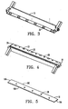
- bed knife 18 of the present invention could be manufactured according to various manufacturing processes. More particularly, as seen in FIGS. 9-15, bed knife 18 may be made of carbon steel, specifically AISI 1566 Hot Rolled Pickled and Oiled steel, which is generally referenced at numeral 100. Carbon steel bed knife 100, like bed knife 18, is adapted to be magnetically held against magnets 20 in an operating position on bed bar 16 as illustrated in FIG. 6 such that bed knife 100 is oriented in cutting relationship with reel 2 in the same fashion as bed knife 18.
- AISI 1566 Hot Rolled Pickled and Oiled steel which is generally referenced at numeral 100.
- Carbon steel bed knife 100 like bed knife 18, is adapted to be magnetically held against magnets 20 in an operating position on bed bar 16 as illustrated in FIG. 6 such that bed knife 100 is oriented in cutting relationship with reel 2 in the same fashion as bed knife 18.
- a generally planar blank 101 is first cut to length. Planar blank 101 is then fed through a stamping or pressing machine that first flattens and straightens planar blank 101 and then imparts a bending force upon the blank.
- the present shape of bed knife 100 includes a generally planar mounting portion 102 and an upturned cutting portion 104.
- upturned cutting portion 104 initially includes a radius portion 106 interconnecting a distal end 108 with mounting portion 102.
- radius portion 106 includes an outer surface 110 that, as seen in FIG.
- this condition of outer surface 110 extending below lower surface 112 is undesirable as it may impede proper turf cutting and/or may contact the ground surface. Furthermore, this condition may further limit the reel mower's minimum cutting height. Accordingly, it is preferable to grind off this outer surface 110 to define a generally unobstructed lower surface.
- bed knife 100 is illustrated following completion of a series of grinding operations sufficient to remove outer surface 110 and define a plurality of faces to create a final desired shape.
- bed knife 100 includes a tournament cut face 114 extending upwardly from lower surface 112 of mounting portion 102.
- tournament cut face 114 extends upwardly from lower surface 112 at a relative angle of about 5 degrees.
- tournament cut face 114 transitions into a super tournament cut face 116 that extends further upwardly at a greater inclination of about 8 degrees relative to lower surface 112.
- Bed knife 100 includes a front face 118, which is at about 90 degrees relative to lower surface 112, and a top face 120, which is at about 8 to 10 degrees relative to lower surface 112.
- tournament cut face 114, super tournament cut face 116, front face 118, and top face 120 are each formed through various grinding operations that requires bed knife 100 to be fed through a milling machine. Following these grinding operations, bed knife 100 is then heat-treated to provide sufficient hardness to reduce the wear of bed knife 100 during operation.
- bed knife 100 further includes a pair of apertures 122 formed through mounting portion 102. This pair of apertures 122 is used during manufacturing to position bed knife 100 during subsequent grinding operations. Additionally, a second pair of apertures 124 is formed through mounting portion 102. This second pair of apertures 124 is sized, similar to holes 28, to receive pegs 26 of bed bar 16.
- top face 120 is finish ground down such that it is about 5.5 degrees inclined relative to lower surface 112.
- front face 118 is ground down to create a cutting edge 126 in place of edge 121. The particular inclination of cutting edge 126 is dependent upon the desired cutting configuration relative to reel 2.
- bed knife 100 provides a number of beneficial cutting properties and prolonged wear, the manufacturing thereof may lead to undesirably high costs and complexity. Therefore, a second embodiment of the present invention provides a preferred method of manufacturing the bed knife which is capable of eliminating many of the grinding steps, heat treatment, and complexity of construction.
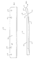
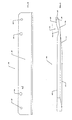
- bed knife 200 is illustrated being manufactured from a simplified process. More particularly, bed knife 200 is made of spring steel, specifically C1095 Scaleless Blue-Tempered Spring Steel, ASTM A682, which is hardened to a minimum Rockwell number of about 47C. Spring steel bed knife 200, like bed knifes 18 and 100, is adapted to be magnetically held against magnets 20 in an operating position on bed bar 16 as illustrated in FIG. 6 such that bed knife 200 is oriented in cutting relationship with reel 2 in the same fashion as bed knife 18.
- spring steel bed knife 200 like bed knifes 18 and 100, is adapted to be magnetically held against magnets 20 in an operating position on bed bar 16 as illustrated in FIG. 6 such that bed knife 200 is oriented in cutting relationship with reel 2 in the same fashion as bed knife 18.
- a generally planar blank (not shown) is fed into a cold roll-forming machine that imparts a bending force upon the blank.
- the planar blank is a roll of spring steel that can quickly and easily be shaped in a continuous, uninterrupted process.
- the blank is shaped through a series of rollers into a desired shape. Due to the nature of spring steel, this shaping process may require one or more bending and over bending operations to produce the desired final shape.
- the present shape of bed knife 200 includes a generally planar mounting portion 202 and an upturned cutting portion 204. As best seen in FIG. 17, upturned cutting portion 204 extends upwardly from mounting portion 202 at a relative angle of about 9 degrees.
- the cold roll forming process of the present embodiment does not create such effect, thereby eliminating the need to grind tournament cut face 114 and super tournament cut face 116. Therefore, the use of spring steel permits the use of roll forming rather than stamping, which eliminates a number of grinding operations, but for a final grind of front face 218 to define a cutting surface.
- bed knife 200 further includes a pair of apertures 224 are formed through mounting portion 202. This pair of apertures 224 is sized, similar to holes 28, to receive pegs 26 of bed bar 16.
- Spring steel bed knife 200 provides a number of advantages over conventional screw-on bed knives and, even, bed knife 100. Specifically, bed knife 200, being made of spring steel, enables it to be made according to a simple cold roll forming technique. This technique, which has not been used before to form magnetic bed knives, dramatically simplifies the manufacturing process, thereby eliminating the need for complex flattening, straightening, forming, grinding, and heat-treating operations.
- a method of manufacturing a bed knife for a reel mower includes cold roll forming spring steel, flattening and straightening the spring steel, shaping the spring steel through a plurality of rollers to impart a bending force upon the spring steel to define a mounting portion and an upturned portion, and grinding a portion of the upturned portion to form a cutting edge.
Landscapes
- Life Sciences & Earth Sciences (AREA)
- Environmental Sciences (AREA)
- Engineering & Computer Science (AREA)
- Mechanical Engineering (AREA)
- Harvester Elements (AREA)
Priority Applications (2)
| Application Number | Priority Date | Filing Date | Title |
|---|---|---|---|
| EP05252752A EP1609347A1 (de) | 2004-05-04 | 2005-05-04 | Gegenmesseranordnung für Spindelmäher |
| EP05252753A EP1593297A1 (de) | 2004-05-04 | 2005-05-04 | Gegenmesseranordnung für Spindelmäher |
Applications Claiming Priority (2)
| Application Number | Priority Date | Filing Date | Title |
|---|---|---|---|
| US10/838,862 US20050246885A1 (en) | 2004-05-04 | 2004-05-04 | Bed knife and method of forming |
| US838862 | 2004-05-04 |
Publications (1)
| Publication Number | Publication Date |
|---|---|
| EP1593453A1 true EP1593453A1 (de) | 2005-11-09 |
Family
ID=34940348
Family Applications (1)
| Application Number | Title | Priority Date | Filing Date |
|---|---|---|---|
| EP05250076A Withdrawn EP1593453A1 (de) | 2004-05-04 | 2005-01-10 | Gegenmesser und Herstellungsverfahren |
Country Status (5)
| Country | Link |
|---|---|
| US (1) | US20050246885A1 (de) |
| EP (1) | EP1593453A1 (de) |
| JP (1) | JP3884752B2 (de) |
| KR (1) | KR100645392B1 (de) |
| CN (1) | CN1692690A (de) |
Cited By (2)
| Publication number | Priority date | Publication date | Assignee | Title |
|---|---|---|---|---|
| CN103028919A (zh) * | 2012-12-31 | 2013-04-10 | 马鞍山市绿之友机械制造有限公司 | 一种草坪机底刀的生产加工方法 |
| CN109514201A (zh) * | 2018-12-07 | 2019-03-26 | 中国重汽集团济南动力有限公司 | 一种重型越野汽车车架加强板的冷冲压工艺 |
Families Citing this family (6)
| Publication number | Priority date | Publication date | Assignee | Title |
|---|---|---|---|---|
| US6760772B2 (en) | 2000-12-15 | 2004-07-06 | Qualcomm, Inc. | Generating and implementing a communication protocol and interface for high data rate signal transfer |
| KR100790591B1 (ko) * | 2006-06-29 | 2008-01-02 | 김종진 | 동력축과 평행한 회전날을 갖는 안전 제초기 |
| US20150319921A1 (en) * | 2014-05-07 | 2015-11-12 | Textron, Inc. | Cylinder mower bedbar assembly |
| USD871459S1 (en) * | 2016-02-11 | 2019-12-31 | Phiston Technologies, Inc. | Mill core bed knife |
| CN109419390B (zh) * | 2017-08-31 | 2022-03-01 | 佛山市顺德区美的电热电器制造有限公司 | 搅拌刀具组件、驱动磁盘组件与食物处理机 |
| CN112889518A (zh) * | 2021-01-21 | 2021-06-04 | 全若波 | 一种道路工程用绿化带修剪装置 |
Citations (9)
| Publication number | Priority date | Publication date | Assignee | Title |
|---|---|---|---|---|
| US2045386A (en) * | 1935-03-28 | 1936-06-23 | Frederick P Gottschalk | Stationary blade for lawn mowers |
| US2183545A (en) * | 1937-06-18 | 1939-12-19 | Clemson Bros Inc | Mower |
| US2557897A (en) * | 1946-08-28 | 1951-06-19 | Reading Hardware Corp | Cutter bar for lawn mowers |
| US5291724A (en) * | 1992-02-14 | 1994-03-08 | T.I. International, Inc. | Reel assembly for mower |
| US5477666A (en) * | 1993-08-20 | 1995-12-26 | T.I. International, Inc. | Reel assembly for mower |
| US6318059B1 (en) * | 2000-01-28 | 2001-11-20 | Bush Hog, L.L.C. | Mower and reel with axially offset chevron blade apexes |
| CA2389770A1 (en) * | 2002-06-07 | 2003-12-07 | Suncaddy Canada Inc. | Magnetic attachment of bedknife in a reel mower assembly |
| US20030226344A1 (en) * | 2002-06-07 | 2003-12-11 | Jeff Buchko | Magnetic attachment of a bed knife in a reel mower assembly |
| WO2003103374A1 (en) * | 2002-06-07 | 2003-12-18 | Suncaddy Canada Inc. | Magnetic attachment of a bed knife in a reel mower assembly |
Family Cites Families (33)
| Publication number | Priority date | Publication date | Assignee | Title |
|---|---|---|---|---|
| US1355509A (en) * | 1919-12-08 | 1920-10-12 | Ross Cleland Coldwell | Stationary knife for lawn-mowers |
| US1754428A (en) * | 1926-02-03 | 1930-04-15 | Huber John | Method and machine for flanging plates |
| US2016230A (en) * | 1934-08-01 | 1935-10-01 | Reading Hardware Corp | Lawn mower construction |
| US2260297A (en) * | 1939-02-14 | 1941-10-28 | Clemson Bros Inc | Mower |
| US2266307A (en) * | 1939-02-14 | 1941-12-16 | Clemson Bros Inc | Mower |
| US2495372A (en) * | 1945-08-02 | 1950-01-24 | Pioneer Gen E Motor Corp | Reel and cutter blade for lawn mowers |
| US2521059A (en) * | 1945-08-02 | 1950-09-05 | Pioneer Gen E Motor Corp | Method of forming cutter blades and reels for lawn mowers and the like |
| US2495812A (en) * | 1947-07-02 | 1950-01-31 | Paul R Hutchinson | Lawn mower blade |
| US2786321A (en) * | 1955-03-29 | 1957-03-26 | Motor Wheel Corp | Knife bar for reel type lawn mower |
| US2869309A (en) * | 1956-12-27 | 1959-01-20 | Toro Mfg Corp | Reel-type mower |
| US2896390A (en) * | 1957-02-18 | 1959-07-28 | Cunningham Ira | Automatic equalizer adjustment mechanism for reel type lawn mowers |
| US2972218A (en) * | 1958-05-23 | 1961-02-21 | Toro Mfg Corp | Power mower with full floating cutting unit |
| US3826121A (en) * | 1973-02-27 | 1974-07-30 | K Yashiro | Method and apparatus for cold bending h-shaped steel |
| US4031734A (en) * | 1973-12-22 | 1977-06-28 | Skf Industrial Trading And Development Company B.V. | Method for the production of concentric machine elements |
| US4373241A (en) * | 1977-06-10 | 1983-02-15 | Maloof Ralph P | Method of making propeller blade |
| BG44563A1 (de) * | 1985-12-29 | 1989-01-16 | Tancho P Chochev | |
| US4857412A (en) * | 1986-01-16 | 1989-08-15 | Paul Fleury | Method for forming a planar sheet or plate to a curved shape |
| GB2232867A (en) * | 1989-06-19 | 1991-01-02 | Schumacher Gustav | Cutter blade for mowers |
| GB8920955D0 (en) * | 1989-09-15 | 1989-11-01 | Ransomes Sims & Jefferies Plc | Bottom blade for grass cutting unit |
| US5209054A (en) * | 1990-04-30 | 1993-05-11 | James E. Cummings | Mowing device |
| US5177943A (en) * | 1990-04-30 | 1993-01-12 | Cummings Associates | Mowing device |
| US5251514A (en) * | 1992-11-02 | 1993-10-12 | White Consolidated Industries, Inc. | Method for forming mower blades |
| DE69519876T2 (de) * | 1995-03-15 | 2001-07-26 | Sunds Defibrator Woodhandling Oy, Pori | Schneidmesser und ein verfahren zur erhöhung der festigkeit des messers |
| US5906053A (en) * | 1997-03-14 | 1999-05-25 | Fisher Barton, Inc. | Rotary cutting blade having a laser hardened cutting edge and a method for making the same with a laser |
| DE19735698A1 (de) * | 1997-08-16 | 1999-02-18 | Deere & Co | Verbindung einer Gegenschneide und eines Gegenschneidehalters, Gegenschneide oder Gegenschneidehalter und Maschine |
| US6044637A (en) * | 1998-01-30 | 2000-04-04 | Deere & Company | Bedknife adjustment linkage |
| US6367302B1 (en) * | 2000-11-13 | 2002-04-09 | Hong Soon Park | Method for bending and cutting metal strip material |
| KR100459976B1 (ko) * | 1999-10-15 | 2004-12-03 | 하테부르 움포름마쉬넨 아크티엔게젤샤프트 | 전단장치를 구비한 성형 기계 |
| US6301867B1 (en) * | 2000-03-09 | 2001-10-16 | Textron Inc. | Bed knife blade construction for reel mowers |
| US7434380B2 (en) * | 2002-07-24 | 2008-10-14 | Textron Inc. | Magnetic attachment of a bed knife in a reel mower assembly |
| US6978532B1 (en) * | 2003-11-07 | 2005-12-27 | Jrm, Inc. | Mower bed blade method |
| US20050247039A1 (en) * | 2004-05-04 | 2005-11-10 | Textron Inc. | Disposable magnetic bedknife |
| US20050247040A1 (en) * | 2004-05-04 | 2005-11-10 | Textron Inc. | Disposable bedknife for a mower |
-
2004
- 2004-05-04 US US10/838,862 patent/US20050246885A1/en not_active Abandoned
-
2005
- 2005-01-10 EP EP05250076A patent/EP1593453A1/de not_active Withdrawn
- 2005-02-06 CN CNA2005100076069A patent/CN1692690A/zh active Pending
- 2005-02-22 JP JP2005046301A patent/JP3884752B2/ja not_active Expired - Fee Related
- 2005-03-21 KR KR1020050023100A patent/KR100645392B1/ko not_active Expired - Fee Related
Patent Citations (9)
| Publication number | Priority date | Publication date | Assignee | Title |
|---|---|---|---|---|
| US2045386A (en) * | 1935-03-28 | 1936-06-23 | Frederick P Gottschalk | Stationary blade for lawn mowers |
| US2183545A (en) * | 1937-06-18 | 1939-12-19 | Clemson Bros Inc | Mower |
| US2557897A (en) * | 1946-08-28 | 1951-06-19 | Reading Hardware Corp | Cutter bar for lawn mowers |
| US5291724A (en) * | 1992-02-14 | 1994-03-08 | T.I. International, Inc. | Reel assembly for mower |
| US5477666A (en) * | 1993-08-20 | 1995-12-26 | T.I. International, Inc. | Reel assembly for mower |
| US6318059B1 (en) * | 2000-01-28 | 2001-11-20 | Bush Hog, L.L.C. | Mower and reel with axially offset chevron blade apexes |
| CA2389770A1 (en) * | 2002-06-07 | 2003-12-07 | Suncaddy Canada Inc. | Magnetic attachment of bedknife in a reel mower assembly |
| US20030226344A1 (en) * | 2002-06-07 | 2003-12-11 | Jeff Buchko | Magnetic attachment of a bed knife in a reel mower assembly |
| WO2003103374A1 (en) * | 2002-06-07 | 2003-12-18 | Suncaddy Canada Inc. | Magnetic attachment of a bed knife in a reel mower assembly |
Cited By (4)
| Publication number | Priority date | Publication date | Assignee | Title |
|---|---|---|---|---|
| CN103028919A (zh) * | 2012-12-31 | 2013-04-10 | 马鞍山市绿之友机械制造有限公司 | 一种草坪机底刀的生产加工方法 |
| CN103028919B (zh) * | 2012-12-31 | 2015-04-22 | 马鞍山市绿之友机械制造有限公司 | 一种草坪机底刀的生产加工方法 |
| CN109514201A (zh) * | 2018-12-07 | 2019-03-26 | 中国重汽集团济南动力有限公司 | 一种重型越野汽车车架加强板的冷冲压工艺 |
| CN109514201B (zh) * | 2018-12-07 | 2020-07-10 | 中国重汽集团济南动力有限公司 | 一种重型越野汽车车架加强板的冷冲压工艺 |
Also Published As
| Publication number | Publication date |
|---|---|
| JP3884752B2 (ja) | 2007-02-21 |
| KR100645392B1 (ko) | 2006-11-14 |
| JP2005318888A (ja) | 2005-11-17 |
| CN1692690A (zh) | 2005-11-09 |
| KR20060044468A (ko) | 2006-05-16 |
| US20050246885A1 (en) | 2005-11-10 |
Similar Documents
| Publication | Publication Date | Title |
|---|---|---|
| EP1593453A1 (de) | Gegenmesser und Herstellungsverfahren | |
| US7631479B2 (en) | Adjustable pivot axis for bedknife assembly | |
| CA2394085C (en) | Magnetic attachment of a bedknife in a reel mower assembly | |
| US5123237A (en) | Sickle blade guide | |
| US6301867B1 (en) | Bed knife blade construction for reel mowers | |
| US3455093A (en) | Adjusting holddown clip | |
| US20070137161A1 (en) | Disposable magnetic bedknife | |
| US7464527B2 (en) | Adjustable hold-down for sickle guards | |
| EP1467609B1 (de) | Magnetische befestigung des gegenmessers für spindelmäher | |
| CA2490960A1 (en) | Bed knife and method of forming | |
| US20050166567A1 (en) | Magnetic attachment of a bed knife in a reel mower assembly | |
| US2045386A (en) | Stationary blade for lawn mowers | |
| US20050247040A1 (en) | Disposable bedknife for a mower | |
| US6735931B1 (en) | Stud plate for sickle bar hold-down | |
| EP1593297A1 (de) | Gegenmesseranordnung für Spindelmäher | |
| EP1609347A1 (de) | Gegenmesseranordnung für Spindelmäher | |
| KR200343322Y1 (ko) | 타일 커팅기의 직각도 조절장치 | |
| US6955035B2 (en) | Mechanism for preventing misalignment of hold-down | |
| CN1692692A (zh) | 一次性的磁性底刀 | |
| CN1692691A (zh) | 割草机所用的一次性底刀 |
Legal Events
| Date | Code | Title | Description |
|---|---|---|---|
| PUAI | Public reference made under article 153(3) epc to a published international application that has entered the european phase |
Free format text: ORIGINAL CODE: 0009012 |
|
| AK | Designated contracting states |
Kind code of ref document: A1 Designated state(s): AT BE BG CH CY CZ DE DK EE ES FI FR GB GR HU IE IS IT LI LT LU MC NL PL PT RO SE SI SK TR |
|
| AX | Request for extension of the european patent |
Extension state: AL BA HR LV MK YU |
|
| AKX | Designation fees paid |
Designated state(s): AT BE BG CH CY CZ LI |
|
| 17P | Request for examination filed |
Effective date: 20050403 |
|
| RBV | Designated contracting states (corrected) |
Designated state(s): AT BE BG CH CY CZ DE DK EE ES FI FR GB GR HU IE IS IT LI LT LU MC NL PL PT RO SE SI SK TR |
|
| R17P | Request for examination filed (corrected) |
Effective date: 20060403 |
|
| REG | Reference to a national code |
Ref country code: DE Ref legal event code: 8566 |
|
| 17Q | First examination report despatched |
Effective date: 20050403 |
|
| RAP1 | Party data changed (applicant data changed or rights of an application transferred) |
Owner name: TEXTRON INNOVATIONS INC. |
|
| STAA | Information on the status of an ep patent application or granted ep patent |
Free format text: STATUS: THE APPLICATION IS DEEMED TO BE WITHDRAWN |
|
| 18D | Application deemed to be withdrawn |
Effective date: 20120127 |