EP1593413A1 - Elément de retenue ou accessoire prévu pour etre assemblé sur une planche de glisse ou de roulage - Google Patents
Elément de retenue ou accessoire prévu pour etre assemblé sur une planche de glisse ou de roulage Download PDFInfo
- Publication number
- EP1593413A1 EP1593413A1 EP05009783A EP05009783A EP1593413A1 EP 1593413 A1 EP1593413 A1 EP 1593413A1 EP 05009783 A EP05009783 A EP 05009783A EP 05009783 A EP05009783 A EP 05009783A EP 1593413 A1 EP1593413 A1 EP 1593413A1
- Authority
- EP
- European Patent Office
- Prior art keywords
- screw
- base
- screws
- hidden
- head
- Prior art date
- Legal status (The legal status is an assumption and is not a legal conclusion. Google has not performed a legal analysis and makes no representation as to the accuracy of the status listed.)
- Withdrawn
Links
- 230000027455 binding Effects 0.000 title description 2
- 238000009739 binding Methods 0.000 title description 2
- 238000005096 rolling process Methods 0.000 claims description 3
- 238000010276 construction Methods 0.000 description 8
- 230000014759 maintenance of location Effects 0.000 description 4
- 238000000034 method Methods 0.000 description 4
- 239000000463 material Substances 0.000 description 3
- 230000000717 retained effect Effects 0.000 description 3
- 241000446313 Lamella Species 0.000 description 2
- 230000004308 accommodation Effects 0.000 description 1
- 230000000295 complement effect Effects 0.000 description 1
- 238000006073 displacement reaction Methods 0.000 description 1
- 238000005553 drilling Methods 0.000 description 1
- 239000002184 metal Substances 0.000 description 1
- 238000004806 packaging method and process Methods 0.000 description 1
- 230000035515 penetration Effects 0.000 description 1
- 230000000452 restraining effect Effects 0.000 description 1
- 125000006850 spacer group Chemical group 0.000 description 1
Images


Classifications
-
- A—HUMAN NECESSITIES
- A63—SPORTS; GAMES; AMUSEMENTS
- A63C—SKATES; SKIS; ROLLER SKATES; DESIGN OR LAYOUT OF COURTS, RINKS OR THE LIKE
- A63C9/00—Ski bindings
Definitions
- the invention relates to an element such as a retaining element or an accessory provided to be assembled on a board of sliding or rolling.
- ski bindings In this area we know ski bindings. Generally a shoe is held on a ski by two front and rear retaining elements that are assembled on the board.
- the retaining elements are assembled by means of screws which are screwed into blind housings drilled in the ski.
- the screws on the retainer To facilitate the mounting operation of the retaining elements on the board, it is usual pre-mount the screws on the retainer. That is, until the moment of the assembly, the screws are held in their housing ready to be screwed. To realize the assembly, then just put the element on the ski and then screw the screws. then the pre-assembly of the screws, it is arranged so that the screw points are slightly in protrusion, which facilitates the identification of position of the retaining element on the ski.
- the advantage principle of the pre-assembly of the screws is that the operator can realize the assembly of the element of hold on the ski in one operation, without having to relax or search screws in the packaging box.
- Patent application FR 2288692 relates such a method of pre-mounting the screws on a restraint element.
- the patent applications FR 2632201 and FR 2651145 teach to pre-mount the front screw in front of the element of restraint, and maintain it until screwing with a disposable element or a sliding drawer that retracts under the body of the retainer.
- An object of the invention is to provide a solution to this problem and thus to facilitate the assembling the retaining elements which are assembled to the ski using a hidden head screw or more, that is to say a screw whose head is no longer accessible once the element assembled on the ski.
- the element according to the invention is intended to be assembled on a gliding board or driving.
- the element comprises a base, the base being intended to be assembled on the board using a plurality of assembly screws pre-mounted in the base, a part of the screws having a hidden head once the element assembled on the ski, the base having in its lower part of the hooking means cooperating with the hidden head screw (s) by a movement of the base relative to the hidden head screw in one direction determined, and dwells adjusted for the other screws not hidden head with a seat support for the head of these screws.
- the element is characterized by the fact that a shim is placed under the base in the position assembly of the element on the board, that the wedge has openings crossed by each screws, and that the opening of a hidden head screw encloses the threaded portion of said screw so to allow only a rotational movement of the screw on itself, that the opening of a screw to non-hidden head encloses the threaded portion of said screw so as to allow movement of said screw relative to the wedge in a direction parallel to the direction in which the base hooks onto the hidden head screw (s), and at least a portion of the openings has a section locally tightened to exert a braking action on the threaded portion of the screw that runs through it.
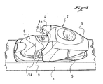
- FIG. 1 is a general view of a retaining element mounted on a ski according to a first embodiment of the invention.
- FIG. 2 is a side view of the retainer of FIG. 1 ready to be assembled on a ski.
- Figure 3 shows the retaining element of the previous figure in a phase intermediate assembly.
- Figure 4 shows a view from below the wedge retaining the assembly screws.
- FIG. 5 is a bottom view of the retaining element ready to be assembled on a ski.
- Figure 6 shows the retaining element seen from below as it is assembled to the ski.
- FIG. 7 to 9 illustrate an alternative embodiment of the invention.
- Figures 10 to 12 relate to another variant.
- FIG. 1 represents a ski portion 1 on which is assembled a front retainer 2.
- the retainer is of any suitable type. According to the illustrated embodiment it has a body 3 with a retaining jaw 4. The body 3 rests on a base 5 which is extended backwards by a support plate 6 provided to receive the sole of shoe.
- the retaining element 2 is equipped with screws for its assembly in the ski.
- holes are made in the ski and the element is assembled to the ski by screwing these screw in the holes.
- Figure 1 we can see the heads of the two rear screws 8 and 9. These heads are visible and accessible even when the product is assembled to the ski.
- Another screw assembly is located at the front of the retainer. This screw is not visible in the Figure 1, it is hidden, that is to say that once the product assembled to the ski, the screw head is more accessible.
- FIGS. 2 and 3 The method of construction of this hidden head screw is illustrated in FIGS. 2 and 3. It is otherwise known from the patent application FR 2651145 cited in the preamble.
- the screw to hidden head 10 is pre-mounted in a sliding drawer 11 which is pulled in front of the base 5 and which retracts inside the base 5 once the screw is screwed into the ski.
- the drawer slide in the longitudinal direction defined by the retaining element. He is guided in a groove or the like which ensures a connection between the drawer and the base in one direction vertical.
- Figure 2 shows the retaining element ready to be assembled on a ski.
- the drawer 11 is out in front of the base 5, the head 10a of the screw 10 is then accessible for a screwdriver or screwdriver.
- the tip 10b of the screw 10 as well as the tip 8b, 9b of the other screws 8 and 9 are slightly protruding from the bottom surface of the element to facilitate placement of the retainer on the ski. We can indeed perceive the moment when the screw head engages in a drilling of the ski.
- Figure 3 shows the retaining element in an intermediate assembly phase.
- the front screw 10 has been screwed into the bore provided for it, and the retainer has been pushed towards the front of the ski so as to slide the base relative to the drawer until that the drawer is retracted inside the base.
- the rear screws 8 and 9 move with the base until they arrive next to the holes provided for them. He then remains screw them to finish the assembly of the retaining element on the ski.
- the heads 8a, 9a of the screws rear 8 and 9 remain accessible after this assembly.
- they can be covered by a piece of clothing which masks them in a removable way thus preserving the accessible character of these screws.
- Figure 4 shows a view from below a shim 12. This shim is also visible in the Figures 2 and 3. It is located under the base and comes into contact with the ski when the element of restraint is assembled on the ski. The wedge 12 raises the retaining element 2. Its function is also to maintain at least a portion of the screws in a pre-assembly position until the assembly of the retaining element on the ski.
- the wedge has in plan a shape and dimensions similar to those of the base of so that these elements cover each other.
- the wedge 12 is cut to form openings 13, 14 and 15 which are traversed by the threaded portion of the screws 8, 9 and 10.
- the openings are tightened at least locally in section so that the threaded portion of the screw is retained by a braking action.
- the opening has two retention zones that have a spacing measured according to a diameter of the threaded portion which is close to the diameter at the bottom of thread of this threaded portion, and less than the diameter at the top of the net. In this way the action braking force exerted by these zones holds the screw in the pre-assembly position until it final tightening.
- the openings that are provided for the non-hidden screws have the shape of a slot oriented in the longitudinal direction defined by the retaining element which is also the sliding direction of the slide 11. These openings enclose the threaded portion of the screws allowing the screws to move on the length of the slot. This length is at least equal to the travel distance of the drawer 11.
- the openings 13 and 14 are delimited respectively by parallel longitudinal edges 13a, 13b and 14a, 14b which form containment areas with a gap between the bottom diameter and the diameter at the crest of a screw.
- the opening 16 which holds the hidden head screw 10 carried by the drawer allows only one rotational movement of the screw 15 on itself.
- each of the retention zones is at the end of a lamella flexible.
- the edges 13b and 14b of the openings 13 and 14 are located at the end of lamellae 17 and 18 formed in the wedge 12 by cutting and oriented transversely.
- the opening 16 it is its retaining zone 16b which is at the end of a lamella 19.
- flexibility of the slats is obtained because of the material used for the wedge and the thickness of the hold in these areas. Any suitable material is suitable for making the hold, and in particular a plastic material. These strips are advantageous because they allow the screw to create more easily its thread between the retaining zones.
- the slats 17 and 18 can be deformed during the circulation of the screws in the slots 13 and 14, so they keep the screws in pre-assembly position without disturbing the movement of the screws in the slots.
- FIG. 5 shows in view from below the shim assembled to the holding element ready to to be assembled on a ski.
- the drawer is then in the position described above in Figure 2.
- the front screw 10 is maintained in the pre-assembly position in the opening 16, and the two rear screws 8, 9 are held in the rear part of the slots 13 and 14, that is to say the furthest part of the opening 16.
- the base is shifted rearwardly relative to the shim 12.
- the wedge 12 holds the screws in pre-assembly position until the assembly of the retaining element on the ski. At the same time the screws hold the wedge attached to the base, so that the whole is in one piece.
- the screw 10 instead of being held in the pre-assembly position through the opening 16 of the shim 12, the screw 10 could be maintained at the level of the slide 11.
- the opening 16 would however retain its longitudinal stop function to prevent the hold advance on the ski when the retainer is pushed forward.
- FIGS. 7 to 9 relate to another variant of construction according to which place the retaining element by means of a sliding drawer, the head screw hidden holds the base directly through his head.
- a mode of construction is for example described in the patent application FR 2632201.
- the hidden screw is held by a shim.
- FIG. 7 shows a retaining element 22 having a base 45 which is provided to be assembled to the ski by a head screw 30 located at the front and screws to head no hidden at the back. Only the screw 29 is visible in the figures.
- the screw 30 has a shouldered head 30a which is provided to enter a shoulder groove 31 opening on the front and having in section a complementary shape so that the screw is able to retain vertically the element of retained once engaged in the groove.
- a shim 42 is located under the retaining element. It presents a construction similar to that of the spacer 12 previously described.
- the front screw 30 is retained at the level an opening 46 which holds the screw in the pre-assembly position, and which prevents a possible relative movement between the screw and the wedge in a longitudinal direction.
- FIGS. 8 and 9 The assembly of the retaining element is illustrated in FIGS. 8 and 9.
- the front screw 30 is screwed into the housing that is assigned to it. This making the front part of the hold is plated and immobilized against the upper surface of the ski. This is illustrated in Figure 8.
- FIGS. 10 and 11 relate to another embodiment adapted to a mode of construction of the front retainer where the retainer hangs on the head shouldered hidden not at a groove opening on the front but at a level buttonhole located in its lower part.
- FIG. 10 shows a retaining element 50 having a base 55 provided for be assembled to the ski using a hidden front screw 60 and rear screw 59.
- the head 60a of the front screw is supported, and is intended to penetrate a housing 51 opening to the underside of the retaining element and accessible by a aperture 53 in the form of a buttonhole.
- the opening 53 has an enlarged area 53a allowing penetration of the screw head and a holding area 53b.
- the opening 53 is made in a metal plate 54 which is assembled to the retaining element. A such mode of construction is known and will not be described in more detail.
- a shim 62 located under the retainer retains the front screw 60 in the pre-assembly position at an opening 66 which holds the screw and which prevents a possible movement in a longitudinal direction.
- the screws are held in a slot-shaped opening, like the slot 64 holding the screw 59.
- the length of the slot is greater than the distance between the edge rear of the opening 53 and the front end of the base 55.
- FIG. 10 The element of FIG. 10 is assembled to a ski according to a procedure similar to that which has been previously described. Initially the element is in the configuration shown in FIG. 10 with the shim 62 in the forward position carrying the screw 60 in front of the restraining element. After screwing the screw 60, the retaining element is pushed back towards the front, and its front is lifted to go over the screw head until it reaches the housing 51 through the opening 53 of the buttonhole. The natural flexibility of the hold allows this longitudinal movement associated with the lifting movement of the front.
- Figure 12 illustrates this phase of moving the body. During this movement the body of the element of retainer 50 and the rear screws 59 advance relative to the shim 62 until the rear screws come right in their respective homes. Then just screw these screws back.
- the number of assembly screws is not limiting, and one could for example to have two screws said hidden or more, and a variable number of screws not hidden.
- the retention slots of the non-hidden screw (s) are oriented parallel to the direction of movement by which the base hooks on the or the screws with hidden head. This direction could be different from the longitudinal direction defined by the retaining element.
- the invention is not limited to the assembly of a front retention element on a ski. It could be adapted to the assembly of a rear restraint, and so general to any retainer or accessory on a board for gliding or rolling directly or on an intermediate mounting block, this assembly implementing a or several screws said hidden and one or more screws not hidden.
- the accessory could be itself an intermediate mounting shim for a traditional retainer.
Landscapes
- Connection Of Plates (AREA)
- Bearings For Parts Moving Linearly (AREA)
Abstract
Description
Claims (7)
- Elément tel qu'un élément de retenue ou un accessoire prévu pour être assemblé sur une planche de glisse ou de roulage, l'élément comprenant une embase, l'embase étant prévue pour être assemblée sur la planche à l'aide d'une pluralité de vis d'assemblage (8, 9, 10, 29, 30, 59, 60) pré-montées dans l'embase (5, 45, 55), une partie des vis (10, 30, 60) ayant une tête cachée une fois l'élément assemblé sur le ski, l'embase ayant dans sa partie inférieure des moyens d'accrochage coopérant avec la ou les vis à tête cachée par un mouvement de l'embase relativement à la vis à tête cachée selon une direction déterminée, et des logements ajustés pour les autres vis à tête non cachée (8, 9, 29, 59) avec un siège d'appui pour la tête de ces vis, caractérisé par le fait qu'une cale (12, 42, 62) est placée sous l'embase dans la position d'assemblage de l'élément sur la planche, que la cale a des ouvertures (13,14, 15, 44, 45, 64, 65) traversées par chacune des vis, et que l'ouverture (15, 45, 65) d'une vis à tête cachée enserre la partie filetée de ladite vis de façon à n'autoriser qu'un mouvement de rotation de la vis sur elle-même, que l'ouverture (13, 14, 44, 64) d'une vis à tête non cachée enserre la partie filetée de ladite vis de façon à permettre un déplacement de ladite vis relativement à la cale selon une direction parallèle à la direction selon laquelle l'embase s'accroche sur la ou les vis à tête cachée, et qu'un partie au moins des ouvertures a une section localement resserrée pour exercer une action de freinage sur la partie filetée de la vis qui la traverse.
- Elément selon la revendication 1, caractérisé par le fait que l'ouverture (13, 14, 44, 64) d'une vis non cachée est une fente délimitée par deux bords parallèles (13a, 13b, 14a, 14b).
- Elément selon la revendication 2, caractérisé par le fait que l'un (13b, 14b) des bords des fentes (13, 14) est l'extrémité d'une lamelle flexible orientée transversalement à la direction de la fente.
- Elément selon la revendication 2, caractérisé par le fait que l'écartement des deux bords (13a, 13b, 14a, 14b) de chaque fente (13, 14) est compris entre le diamètre à fond de filet des vis à tête non cachée (8, 9, 29, 59) et le diamètre en sommet de filet.
- Elément selon la revendication 2 où l'élément est un élément de retenue dont la vis cachée (10) est portée par un tiroir (11) coulissant selon une direction longitudinale définie par son embase, caractérisé par le fait que les fentes (13, 14) sont parallèles à la direction de coulissement du tiroir et qu'elles ont une longueur au moins égale à la course de coulissement du tiroir (11) dans l'embase.
- Elément selon la revendication 2 où l'élément est un élément de retenue dont la vis cachée (30) a une tête épaulée prévue pour pénétrer à l'intérieur d'une rainure (31) débouchant à l'avant de l'embase, caractérisé par le fait que les fentes (44) sont parallèles à l'orientation de la rainure (31) et que leur longueur est supérieure à la longueur de la rainure.
- Elément selon la revendication 2 où l'élément est un élément de retenue dont la vis cachée (60) a une tête épaulée prévue pour pénétrer dans un logement (51) située sous l'embase et accessible par une ouverture (53) en forme de boutonnière, caractérisé par le fait que la longueur des fentes (64) est supérieure à la distance entre l'extrémité arrière de l'ouverture de la boutonnière et l'extrémité avant de l'embase.
Applications Claiming Priority (2)
| Application Number | Priority Date | Filing Date | Title |
|---|---|---|---|
| FR0404848A FR2869812B1 (fr) | 2004-05-05 | 2004-05-05 | Element de retenue ou accessoire prevu pour etre assemble sur une planche de glisse ou de roulage |
| FR0404848 | 2004-05-05 |
Publications (1)
| Publication Number | Publication Date |
|---|---|
| EP1593413A1 true EP1593413A1 (fr) | 2005-11-09 |
Family
ID=34936141
Family Applications (1)
| Application Number | Title | Priority Date | Filing Date |
|---|---|---|---|
| EP05009783A Withdrawn EP1593413A1 (fr) | 2004-05-05 | 2005-05-04 | Elément de retenue ou accessoire prévu pour etre assemblé sur une planche de glisse ou de roulage |
Country Status (2)
| Country | Link |
|---|---|
| EP (1) | EP1593413A1 (fr) |
| FR (1) | FR2869812B1 (fr) |
Citations (3)
| Publication number | Priority date | Publication date | Assignee | Title |
|---|---|---|---|---|
| FR2288692A1 (fr) | 1974-10-21 | 1976-05-21 | Cayot Robert | Dispositif pour l'approvisionnement en boites vides d'un poste, notamment de marquage ou de remplissage de ces boites |
| FR2632201A1 (fr) | 1988-06-07 | 1989-12-08 | Salomon Sa | Fixation de securite pour ski |
| FR2651145A1 (fr) | 1989-08-22 | 1991-03-01 | Salomon Sa | Fixation de securite pour ski. |
-
2004
- 2004-05-05 FR FR0404848A patent/FR2869812B1/fr not_active Expired - Fee Related
-
2005
- 2005-05-04 EP EP05009783A patent/EP1593413A1/fr not_active Withdrawn
Patent Citations (3)
| Publication number | Priority date | Publication date | Assignee | Title |
|---|---|---|---|---|
| FR2288692A1 (fr) | 1974-10-21 | 1976-05-21 | Cayot Robert | Dispositif pour l'approvisionnement en boites vides d'un poste, notamment de marquage ou de remplissage de ces boites |
| FR2632201A1 (fr) | 1988-06-07 | 1989-12-08 | Salomon Sa | Fixation de securite pour ski |
| FR2651145A1 (fr) | 1989-08-22 | 1991-03-01 | Salomon Sa | Fixation de securite pour ski. |
Also Published As
| Publication number | Publication date |
|---|---|
| FR2869812B1 (fr) | 2006-08-04 |
| FR2869812A1 (fr) | 2005-11-11 |
Similar Documents
| Publication | Publication Date | Title |
|---|---|---|
| FR2880524A1 (fr) | Dispositif pour la repartition d'au moins un accessoire de presentation au niveau d'une surface d'exposition de marchandises | |
| FR2638654A1 (fr) | Fixation de securite pour ski | |
| EP0422382B1 (fr) | Dispositif antirecul pour ski de fond | |
| EP1329246B1 (fr) | Perfectionnement pour dispositif de retenue d'une chaussure sur une planche de glisse sur neige du type surf | |
| EP1611929A1 (fr) | Fixitation de chaussure de sport sur planche de glisse avec chaussage/dechaussage facilite | |
| FR2608396A1 (fr) | Structure de support reglable pour tablettes d'etageres | |
| FR2635465A1 (fr) | Fixation de securite pour ski | |
| EP1103290A1 (fr) | Fixation de surf | |
| CA2204833A1 (fr) | Chaussure de sport munie d'une voute plantaire reglable | |
| EP1958678B1 (fr) | Ensemble comprenant un dispositif de solidarisation amovible d'une embase à une platine | |
| EP1254685B1 (fr) | Fixation de surf des neiges | |
| FR2572944A1 (fr) | Dispositif de guidage lateral d'une chaussure de ski, fixee a son extremite avant, sur un ski de fond | |
| EP1234604B1 (fr) | Plate-forme de réhaussement de la fixation destinée à être montée sur une planche de glisse | |
| FR2922779A1 (fr) | Ensemble pour la pratique d'un sport de glisse ou de roulage | |
| EP0648142B1 (fr) | Dispositif de retenue d'une chaussure sur une planche de glisse | |
| FR2651145A1 (fr) | Fixation de securite pour ski. | |
| FR2657507A1 (fr) | Chaussure de ski alpin a bas de coque rigide. | |
| EP0548468B1 (fr) | Pièce d'interface pour la glissière d'un élément de fixation, notamment de fixation alpine | |
| FR3122620A1 (fr) | Tablette arriere de vehicule automobile pourvue d’un bac de rangement | |
| FR3008896A1 (fr) | Systeme de fixation reglable pour planche de glisse et planche equipee d’un tel systeme | |
| FR2922778A1 (fr) | Ensemble pour la pratique d'un sport de glisse ou de roulage | |
| FR2674444A1 (fr) | Cales interface pour fixation de securite de ski alpin. | |
| EP0775507B1 (fr) | Fixation de ski équipée d'un frein démontable | |
| FR2934168A1 (fr) | Element de fixation pour planche de glisse avec rattrapage des jeux | |
| EP0932434A1 (fr) | Patin a roulettes, se fixant sur la semelle d'une chaussure de marche |
Legal Events
| Date | Code | Title | Description |
|---|---|---|---|
| PUAI | Public reference made under article 153(3) epc to a published international application that has entered the european phase |
Free format text: ORIGINAL CODE: 0009012 |
|
| AK | Designated contracting states |
Kind code of ref document: A1 Designated state(s): AT BE BG CH CY CZ DE DK EE ES FI FR GB GR HU IE IS IT LI LT LU MC NL PL PT RO SE SI SK TR |
|
| AX | Request for extension of the european patent |
Extension state: AL BA HR LV MK YU |
|
| 17P | Request for examination filed |
Effective date: 20060505 |
|
| AKX | Designation fees paid |
Designated state(s): AT CH DE IT LI SI |
|
| GRAP | Despatch of communication of intention to grant a patent |
Free format text: ORIGINAL CODE: EPIDOSNIGR1 |
|
| STAA | Information on the status of an ep patent application or granted ep patent |
Free format text: STATUS: THE APPLICATION IS DEEMED TO BE WITHDRAWN |
|
| 18D | Application deemed to be withdrawn |
Effective date: 20080605 |