EP1593352A1 - Dental wedge - Google Patents
Dental wedge Download PDFInfo
- Publication number
- EP1593352A1 EP1593352A1 EP05009869A EP05009869A EP1593352A1 EP 1593352 A1 EP1593352 A1 EP 1593352A1 EP 05009869 A EP05009869 A EP 05009869A EP 05009869 A EP05009869 A EP 05009869A EP 1593352 A1 EP1593352 A1 EP 1593352A1
- Authority
- EP
- European Patent Office
- Prior art keywords
- wedge
- tooth
- base
- dental
- bore
- Prior art date
- Legal status (The legal status is an assumption and is not a legal conclusion. Google has not performed a legal analysis and makes no representation as to the accuracy of the status listed.)
- Withdrawn
Links
Images


Classifications
-
- A—HUMAN NECESSITIES
- A61—MEDICAL OR VETERINARY SCIENCE; HYGIENE
- A61C—DENTISTRY; APPARATUS OR METHODS FOR ORAL OR DENTAL HYGIENE
- A61C5/00—Filling or capping teeth
- A61C5/80—Dental aids fixed to teeth during treatment, e.g. tooth clamps
- A61C5/88—Wedges
-
- A—HUMAN NECESSITIES
- A61—MEDICAL OR VETERINARY SCIENCE; HYGIENE
- A61C—DENTISTRY; APPARATUS OR METHODS FOR ORAL OR DENTAL HYGIENE
- A61C2201/00—Material properties
- A61C2201/002—Material properties using colour effect, e.g. for identification purposes
Definitions
- the invention relates to dental wedges for use in the dental treatment and restoration carious Cavities between adjacent teeth.
- the part of a tooth is to be restored before the Infestation with tooth decay has touched an adjacent tooth is It requires the filler material during insertion into the cavity and the subsequent hardening and support it so that it is exactly the healthy one Part of the tooth can adapt.
- a matrix band to lay and tighten the tooth to be treated, so that this the damaged part of the tooth wall during can replace the treatment so to speak. So the matrix band must fulfill its function, it must be so far as possible approximated to the shape of the tooth and in this Position be fixed so that the introduced filling material
- the outer surface of the healthy tooth corresponds and can not survive and form niches, which again favor the formation of caries.
- Dental wedges typically have a conical, elongated Shape and a triangular or even V-shaped Cross-section. During dental treatment, the dental wedge must absolutely immovable in its position between two teeth and must therefore be forceful, i. usually with Help of a special instrument, pressed between the teeth until it is held in place by friction becomes. Also, the dental wedges are available in different sizes offered, thus one of the respective anatomy appropriate Selection can be made.
- US Pat. No. 6,074,210 describes dental wedges whose side view an elongated, pointed triangle and whose cross section resembles an inverted V, ie down where the dental wedge with the interdental papilla in Touch comes, is open. By doing so the sidewalls one To obtain greater elasticity, the insertion of the tooth wedges relieved between two teeth, their grip improved there and as exact as possible adaptation to the shape of the Teeth, also on cavities, and a provision after the Removal can be achieved at the end of treatment.
- the side surfaces should be structured by using a Corrugation or notches are provided. This should their grip between the teeth can be increased again.
- the tooth wedge itself consists of two sections with different Cross-sectional shape.
- the cross section of the first, front section has the shape of a triangle, the Side surfaces are concavely curved inward and longitudinally to a rounded tip converge and the tip is bent upwards.
- the wedge goes over a section with trapezoidal cross-section. This section should during insertion into the interdental space the Spread the teeth additionally.
- This is also closed discontinued by a constriction yet preferably a cuboid Extension to which finally the above mentioned Actuating rod is formed.
- At the cuboid Extension can be the wedge after the dental treatment after the Operating rod was previously broken off, with pliers be taken and removed.
- the object of the invention is to provide a dental wedge, the even better anatomically but still simply shaped and as uncomplicated as possible in the production and with an instrument that the dentist already has at hand, preferably tweezers, but in a simple way with the force required for a secure hold in the Interdental space can be introduced. He should be there as optimally as possible to every possible tooth form, to existing ones Cavities and e.g. also subgingival filling margins below the best possible protection of the papilla.
- this is achieved in that the wedge at its end facing away from the top merges into one frusto-conical or truncated pyramid Tail, on the engagement surfaces for tweezers or another suitable dental gripping instrument is formed are.
- the dental wedge thus receives an anatomically optimally adaptive Shape that meets all the requirements of a dental wedge are covered. He lets himself place exactly between two adjacent teeth and fits there optimally to the shape of the teeth in the range of Cavities, and it is still an optimal wedge effect achieved. Due to the saber-shaped bend of the wedge tip the gum papilla is located at the exit point of the Wedge as best as possible. The concave arched base area clings gently to the papilla and results next to a good wedge effect also a high resilience of the Wedge when removed again after finishing treatment becomes.
- the formation the engagement surfaces for the tweezers or another Dental gripping instrument in the tail a hole brought in.
- the bore is designed as an axial blind hole and at least one side surface of the base is as second engagement surface for a pair of tweezers or another Gripping instrument concavely curved inwards.
- a tweezer arm on the inner surface of the bore and the other tweezer arm engages the side surface of the socket an effectively high, axially directed pressure during Pressing the dental wedge in the interdental space exerted be achieved and the required wedge effect.
- the engagement surface for the gripper or tweezer arm on the side surface of the base can be for a better and be sure to be rifled.
- the bore is as executed through continuous transverse bore and provides the engagement surface for the first gripper or tweezer arm; the Engagement surface for the second gripper or tweezer arm is then preferred at the base of the tail or Skirt formed. Also with this training of the engagement surfaces can the necessary high pressure during pressing of the dental wedge.
- indentations are additionally or alternatively formed in at least two mutually opposite side surfaces of the cuboid base indentations as engagement surfaces for the tweezer or gripping arms If the abutting edges between the base surface and the side surfaces of the wedge are chamfered slightly inwards, a very good adaptation is also achieved at subgingival filling margins.
- the base surface of the wedge may be reflective with a light Structuring, preferably in the manner of a cat's eye Be provided such that the light is optimally in the direction on a die band placed around the tooth to be treated is reflected.
- the tooth wedge is preferably made of a thermoplastic, transparent plastic (elastomer) and can be completely or partially provided with a slight coloring as color coding for different wedge sizes.
- Figs. 1 to 5 show the tooth wedge in four different Sizes but otherwise identical copy and in each case five different views.
- the actual wedge 1 is then bent upwardly in a saber-like manner (see FIGS. 1 to 3) and has a first, longer wedge portion 1a and a second, shorter wedge portion 1b, which at its free end to a preferably rounded, upwards directed tip 2 expires.
- the wedge 1 has a triangular Cross section (see Fig. 5), wherein both the base surface 3 and the side surfaces 4 concave are.
- the abutting edges 5 of the base surface 3 and the two Side surfaces 4 are preferably also rounded.
- the wedge 1 merges into a frusto-conical shape or, as shown, truncated pyramidal wide tail 6, to which still a cuboid Can connect socket 7.
- the side surfaces of the Socket 7 or preferably its opposite, Upper and lower side surface 8 can be concave inwards arched (see FIGS. 1 and 4) and be additionally corrugated (see Fig. 3). From the free end of the base 7 ago is in the base 7 and reaching into the tail 6 a Sack hole 9 introduced.
- Blind hole 9 can on two opposite side surfaces 8 of the base 7 indentations 10 are provided which may be fluted for their purpose (see below).
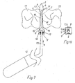
- Fig. 9 it is the purpose of both Blind hole 9 together with one of the concave inwardly arched Side surfaces 8 of the base 7 (see also Fig. 10) and, alternatively, the recesses 10, the possibility to offer the wedge with tweezers 12 too capture and into the space between two adjacent ones Engage and press teeth 13 to there a matrix band (not shown) close to the shape of the teeth thirteenth to press and the teeth 13 to a certain extent spread. If, as shown in Figs.
- Fig. 8 shows a variant of the possibility of holding during insertion and removing the dental wedge.
- a continuous Cross hole 14 provided in the one with the Tweezers arm 12a can be intervened while the other Tweezer arm 12b the base 7 at its base 15th detected. Also in this way can in the axial direction of the Tooth wedge enough high pressure to be applied, because To press tooth wedge firmly between the teeth 13.
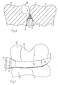
- FIGS. 8 and 9 show how, as a result of the parallelism of the abutting edges 5, the wedge 1 fits particularly well into the interdental space and adapts optimally to the shape of the two adjacent teeth 13 and also to the entry points 16 and the exit points 17 optimally wedged; Retractions 18 on the neck of the tooth are also optimally recorded. From the sectional view of Fig. 6 it is clear how the wedge 1 with its concave inwardly curved base surface 3, the papilla 19 gently, conforms to this. Due to the parallelism of the abutting edges 5, a perfect adaptation is also achieved in the area of cavities 20 and nevertheless a good wedge effect.
- the shape of the base surface 3 gives a high resilience of the wedge 1, when it is removed after completion of the dental treatment.
- the two abutting edges 5 are preferably each provided with a bevel 21 (see also FIG. 11); these chamfers 21 provide for a good adaptation of a matrix band (not shown) placed for the treatment around the tooth, even in the case of subgingival filling margins, that is below the gingival margin. Also in the view of Fig. 7 it can be seen how the curved wedge shape gently nestles against the papilla 19 and the cavity edges are also wedged interdental optimal.
- the tooth wedge is made of a thermoplastic and preferably made of transparent plastic (elastomer) and may advantageously be whole or partial, e.g. at the tail 6 with base 7 a slight coloring as color coding for the different wedge sizes (see FIGS. 1 to 5) exhibit.
- the base surface 3 of the wedge 1 can, e.g. by a treatment with spark erosion, with a Structuring, for example in the manner of a cat's eye, which, as indicated by arrows in FIG. 11, for optimal reflection of the light e.g. on and by a laid around the tooth to be treated, preferably also transparent matrix band provides and so the Making work more comfortable for the dentist.
Abstract
Description
Die Erfindung bezieht sich auf Zahnkeile zur Verwendung bei der zahnmedizinischen Behandlung und Restauration kariöser Hohlräume zwischen benachbarten Zähnen.The invention relates to dental wedges for use in the dental treatment and restoration carious Cavities between adjacent teeth.
Wenn der Teil eines Zahnes zu restaurieren ist, der vor dem Befall mit Karies einen benachbarten Zahn berührt hat, ist es erforderlich, das Füllmaterial während des Einbringens in den Hohlraum und der anschließenden Aushärtung einzugrenzen und abzustützen, damit es sich exakt dem gesunden Teil des Zahnes anpassen kann. Dazu ist es üblich, ein Matrizenband um den zu behandelnden Zahn zu legen und festzuziehen, damit dieses den zerstörten Teil der Zahnwand während der Behandlung sozusagen ersetzen kann. Damit das Matrizenband seine Funktion erfüllen kann, muss es so soweit als möglich der Form des Zahnes angenähert und in dieser Position fixiert werden, so dass das eingebrachte Füllmaterial schließlich der Außenfläche des gesunden Zahnes entspricht und nicht übersteht und sich Nischen bilden können, die erneut die Bildung von Karies begünstigen. Zu diesem Zweck wird ein Zahnkeil zwischen die benachbarten Zähne und das Zahnfleisch gedrückt, der das Matrizenband gegen den zu behandelnden Zahn drückt und festkeilt und gleichzeitig auch die Zähne etwas auseinander drückt. Damit wird erreicht, dass, wenn nach abgeschlossener Behandlung das Matrizenband wieder entfernt wird, die Zähne sich wieder gegenseitig abstützen können, indem sie in ihre Ausgangslage zurückkehren und nicht der vom Matrizenband zuvor beanspruchte Raum als Lücke oder Spalt bestehen bleibt. Zahnkeile haben typischerweise eine konische, langgestreckte Form und einen dreieckigen oder auch V-förmigen Querschnitt. Während einer Zahnbehandlung muss der Zahnkeil in seiner Stellung zwischen zwei Zähnen absolut unverrückbar sein und muss deshalb mit Kraft, d.h. üblicherweise mit Hilfe eines speziellen Instruments, zwischen die Zähne gepresst werden, bis er dort durch Reibung in Position gehalten wird. Auch werden die Zahnkeile in verschiedenen Größen angeboten, damit eine der jeweiligen Anatomie entsprechende Auswahl getroffen werden kann.If the part of a tooth is to be restored before the Infestation with tooth decay has touched an adjacent tooth is It requires the filler material during insertion into the cavity and the subsequent hardening and support it so that it is exactly the healthy one Part of the tooth can adapt. For this it is customary, a matrix band to lay and tighten the tooth to be treated, so that this the damaged part of the tooth wall during can replace the treatment so to speak. So the matrix band must fulfill its function, it must be so far as possible approximated to the shape of the tooth and in this Position be fixed so that the introduced filling material Finally, the outer surface of the healthy tooth corresponds and can not survive and form niches, which again favor the formation of caries. To this The purpose is a dental wedge between the adjacent teeth and The gums pressed against the matrix band against the treating tooth presses and locks and at the same time also pushes the teeth apart. This is achieved if, after completing treatment, the matrix band is removed again, the teeth again each other can support them by putting them in their starting position return and not the one previously claimed by the matrix band Space remains as a gap or gap. Dental wedges typically have a conical, elongated Shape and a triangular or even V-shaped Cross-section. During dental treatment, the dental wedge must absolutely immovable in its position between two teeth and must therefore be forceful, i. usually with Help of a special instrument, pressed between the teeth until it is held in place by friction becomes. Also, the dental wedges are available in different sizes offered, thus one of the respective anatomy appropriate Selection can be made.
Das US-Patent 6,074,210 beschreibt Zahnkeile, deren Seitenansicht einem langgestreckten, spitz zulaufenden Dreieck und deren Querschnitt einem umgedrehten V gleicht, also nach unten, wo der Zahnkeil mit der Interdentalpapille in Berührung kommt, offen ist. Indem so die Seitenwände eine größere Elastizität erhalten, soll das Einführen der Zahnkeile zwischen zwei Zähne erleichtert, ihr Halt dort verbessert und eine möglichst exakte Anpassung an die Form der Zähne, auch an Kavitäten, sowie eine Rückstellung nach der Entnahme am Ende der Behandlung erreicht werden. Die Seitenflächen sollen strukturiert sein, indem sie mit einer Riffelung oder mit Einkerbungen versehen sind. Dadurch soll ihr Halt zwischen den Zähnen nochmals gesteigert werden. An ihrem von der Spitze abgewandten, breiten Ende weisen die Zahnkeile einen würfelförmigen Fortsatz auf, an dem sie mit einem geeigneten Instrument, z.B. einer Zange, ergriffen werden und zwischen zwei Zähne mit ausreichend Kraft eingepresst werden können, um den erforderlichen Halt zu finden. Die beiden unteren Längskanten sind auf etwa halber Länge stumpf abgewinkelt, wodurch eine bessere Anpassung an die Anatomie eines Patienten erreicht werden soll. US Pat. No. 6,074,210 describes dental wedges whose side view an elongated, pointed triangle and whose cross section resembles an inverted V, ie down where the dental wedge with the interdental papilla in Touch comes, is open. By doing so the sidewalls one To obtain greater elasticity, the insertion of the tooth wedges relieved between two teeth, their grip improved there and as exact as possible adaptation to the shape of the Teeth, also on cavities, and a provision after the Removal can be achieved at the end of treatment. The side surfaces should be structured by using a Corrugation or notches are provided. This should their grip between the teeth can be increased again. At their facing away from the top, wide end have the Zahnkeile a cube-shaped extension on which they with a suitable instrument, e.g. a pair of pliers, grabbed be pressed between two teeth with sufficient force be able to find the required stop. The two lower longitudinal edges are at about half the length angled dull, which allows better adaptation to the Anatomy of a patient should be achieved.
Nachteilig an diesen Zahnkeilen ist, dass durch die nach unten offene Form der Keileffekt gemindert wird. Riffelungen oder Einkerbungen an den Seitenflächen wirken einer optimalen Anpassung an die in jedem Behandlungsfall verschiedenen anatomischen Gegebenheiten entgegen. Auch dass für das Einführen der Zahnkeile eine besondere Zange benötigt wird, wird als nachteilig empfunden.A disadvantage of these wedges is that by the after bottom open shape of the wedge effect is reduced. corrugations or notches on the side surfaces have an optimal effect Adaptation to the different in each treatment case contrary to anatomical conditions. Also that for the insertion of the tooth wedges requires special pliers is felt to be detrimental.
Dieser letztgenannte Nachteil wird mit der US-Patentanmeldung 2004/0014006 A1 vermieden, wonach vorgeschlagen wird, jeden Zahnkeil über eine Einschnürung mit einem angeformten Betätigungsstab zu versehen, also beide Teile einstückig auszubilden. Für die Betätigung kann der Stab an der Einschürung bei Bedarf abgewinkelt oder abgebogen werden. Nach dem Einpressen des Zahnkeils in den Zahnzwischenraum wird der Betätigungsstab abgebrochen und weggeworfen. Dies bedeutet eine enorme Materialverschwendung; der Betätigungsstab muss im Vergleich zum eigentlichen Zahnkeil verhältnismäßig lang und auch kräftig ausgebildet sein, damit mit ihm die erforderliche Kraft auf den Zahnkeil beim Einpressen ausgeübt werden kann. Dass sich der Betätigungsstab an der Einschnürung abwinkeln oder abbiegen lässt, kann sich als Nachteil erweisen, da dabei der Kraftvektor in Schubrichtung vermindert wird.This latter disadvantage is with the US patent application 2004/0014006 A1, according to which it is proposed each wedge over a constriction with a molded Actuating rod to provide, so both parts in one piece train. For the actuation of the rod at the Einschürung angled or bent if necessary. To the pressing of the tooth wedge in the interdental space is the actuating rod was broken off and thrown away. this means a huge waste of material; the actuating rod must be proportionate compared to the actual dental wedge be long and strong, so with give it the required force on the tooth wedge when pressing in can be exercised. That the actuating rod to can bend or constrict the constriction, can prove to be a disadvantage, as doing the force vector in the thrust direction is reduced.
Der Zahnkeil selbst besteht aus zwei Abschnitten mit unterschiedlicher Querschnittsform. Der Querschnitt des ersten, vorderen Abschnitts hat die Form eines Dreiecks, wobei die Seitenflächen konkav nach innen gewölbt sind und in Längsrichtung zu einer abgerundeten Spitze aufeinander zulaufen und die Spitze nach oben gebogen ist. Am von der Spitze abgewandten Ende dieses Abschnitts geht der Keil über in einen Abschnitt mit trapezoidem Querschnitt. Dieser Abschnitt soll beim Einführen in den Zahnzwischenraum die Zähne zusätzlich spreizen. Daran schließt sich ebenfalls durch eine Einschnürung abgesetzt noch ein bevorzugt quaderförmiger Fortsatz an, an den schließlich der oben erwähnte Betätigungsstab angeformt ist. An dem quaderförmigen Fortsatz kann der Keil nach der Zahnbehandlung, nachdem der Betätigungsstab zuvor abgebrochen wurde, mit einer Zange ergriffen und entfernt werden. Das bedeutet, auch nach diesem Vorschlag eines Zahnkeils mit angeformtem aber abbrechbarem Betätigungsstab, kommt der Zahnarzt letztlich nicht ohne ein weiteres Instrument aus, und es ist der erwähnte Fortsatz als Verbindungsstück zwischen dem eigentlichen Zahnkeil und dem Betätigungsstab notwendig. Die Gesamtform mit den unterschiedlichen Abschnitten und Teilen wird damit kompliziert und aufwendig in der Herstellung.The tooth wedge itself consists of two sections with different Cross-sectional shape. The cross section of the first, front section has the shape of a triangle, the Side surfaces are concavely curved inward and longitudinally to a rounded tip converge and the tip is bent upwards. At the point away from the top At the end of this section, the wedge goes over a section with trapezoidal cross-section. this section should during insertion into the interdental space the Spread the teeth additionally. This is also closed discontinued by a constriction yet preferably a cuboid Extension to which finally the above mentioned Actuating rod is formed. At the cuboid Extension can be the wedge after the dental treatment after the Operating rod was previously broken off, with pliers be taken and removed. That means, even after this Proposal of a dental wedge with integrally formed but breakable Acting staff, the dentist does not come ultimately without another instrument, and it's the one mentioned Extension as a connecting piece between the actual Tooth wedge and the operating rod necessary. The overall shape with the different sections and parts becomes with it complicated and expensive to manufacture.
Aufgabe der Erfindung ist es, einen Zahnkeil zu schaffen, der noch besser anatomisch aber dennoch einfach geformt und möglichst unkompliziert in der Herstellung ist und der mit einem Instrument, das der Zahnarzt ohnehin zur Hand hat, vorzugsweise einer Pinzette, in einfacher Weise aber mit der für einen sicheren Halt erforderlichen Kraft in den Zahnzwischenraum eingeführt werden kann. Dort soll er sich möglichst optimal an jede mögliche Zahnform, an vorhandene Kavitäten und z.B. auch subgingivale Füllungsränder unter möglichster Schonung der Papille anpassen können.The object of the invention is to provide a dental wedge, the even better anatomically but still simply shaped and as uncomplicated as possible in the production and with an instrument that the dentist already has at hand, preferably tweezers, but in a simple way with the force required for a secure hold in the Interdental space can be introduced. He should be there as optimally as possible to every possible tooth form, to existing ones Cavities and e.g. also subgingival filling margins below the best possible protection of the papilla.
Erfindungsgemäß wird dies dadurch erreicht, dass der Keil an seinem von der Spitze abgewandten Ende übergeht in ein sich kegelstumpfförmig oder pyramidenstumpfförmig weitendes Endstück, an dem Eingriffsflächen für eine Pinzette oder ein anderes geeignetes, zahnärztliches Greifinstrument ausgebildet sind.According to the invention this is achieved in that the wedge at its end facing away from the top merges into one frusto-conical or truncated pyramid Tail, on the engagement surfaces for tweezers or another suitable dental gripping instrument is formed are.
Indem so auf besondere Fortsätze, an denen der Keil erfasst
werden kann, verzichtet wird, erhält der Zahnkeil eine verhältnismäßig
einfache Gesamtform, die sich kostensenkend
bei der Herstellung und beim Materialverbrauch auswirkt.
Gleichzeitig zeichnet er sich durch eine einfache Handhabung
aus, indem der behandelnde Zahnarzt den Zahnkeil mit
einem Instrument, das er ohnedies zur Hand hat, an den vorgesehenen
Eingriffsflächen sicher und fest fassen und exakt
plazieren kann.
Eine besonders vorteilhafte Ausführungsform des Zahnkeiles
weist außerdem die folgenden Merkmale in Kombination auf:
- der Keil ist säbelförmig nach oben gebogen,
- die Basisfläche und die Seitenflächen des Keils sind konkav nach innen gewölbt,
- die Stoßkanten der Basisfläche und der Seitenflächen des Keils sind abgerundet,
- der Keil weist einen ersten, längeren Keilabschnitt und einen zweiten, kürzeren Keilabschnitt auf, wobei die Stoßkanten zwischen der Basisfläche und den Seitenflächen im ersten Keilabschnitt zueinander parallel verlaufen und erst im zweiten Keilabschnitt zur freien, nach oben gebogenen Spitze des Keils aufeinander zulaufen.
A particularly advantageous embodiment of the tooth wedge also has the following features in combination:
- the wedge is saber-shaped bent upwards,
- the base surface and the side surfaces of the wedge are concavely curved inwards,
- the abutting edges of the base surface and the side surfaces of the wedge are rounded,
- the wedge has a first, longer wedge portion and a second, shorter wedge portion, wherein the abutting edges between the base surface and the side surfaces in the first wedge portion parallel to each other and only in the second wedge portion to the free, upwardly bent tip of the wedge converge.
Der Zahnkeil erhält so eine sich anatomisch bestens anpassende Form, mit der alle Erfordernisse, die an einen Zahnkeil gestellt werden können, abgedeckt sind. Er lässt sich exakt zwischen zwei benachbarten Zähnen plazieren und passt sich dort optimal an die Form der Zähne auch im Bereich von Kavitäten an, und es wird dabei doch ein optimaler Keileffekt erzielt. Durch die säbelförmige Aufbiegung der Keilspitze wird die Zahnfleischpapille am Austrittspunkt des Keiles größtmöglich geschont. Die konkav gewölbte Basisfläche schmiegt sich schonend an die Papille und ergibt neben einem guten Keileffekt auch ein hohes Rückstellvermögen des Keiles, wenn der nach beendeter Behandlung wieder entnommen wird. Durch die Parallelität der Stoßkanten zwischen der Basisfläche und den Seitenflächen im Bereich des ersten, längeren Keilabschnitts wird eine optimale Verkeilung sowohl an den Eintritts- als auch an den Austrittspunkten am Zahnzwischenraum erzielt, auch Einziehungen am Zahnhals werden optimal erfasst.The dental wedge thus receives an anatomically optimally adaptive Shape that meets all the requirements of a dental wedge are covered. He lets himself place exactly between two adjacent teeth and fits there optimally to the shape of the teeth in the range of Cavities, and it is still an optimal wedge effect achieved. Due to the saber-shaped bend of the wedge tip the gum papilla is located at the exit point of the Wedge as best as possible. The concave arched base area clings gently to the papilla and results next to a good wedge effect also a high resilience of the Wedge when removed again after finishing treatment becomes. Due to the parallelism of the abutting edges between the Base surface and the side surfaces in the area of the first, longer wedge section will provide optimal wedging both at the entry and exit points on the Interstitial space is achieved, including retractions on the neck of the tooth are optimally recorded.
Nach einer Ausführungsform der Erfindung ist zur Bildung der Eingriffsflächen für die Pinzette oder ein anderes zahnärztliches Greifinstrument in das Endstück eine Bohrung eingebracht.According to one embodiment of the invention, the formation the engagement surfaces for the tweezers or another Dental gripping instrument in the tail a hole brought in.
Vorteilhaft schließt sich an das Endstück noch ein quaderförmiger Sockel an, der ebenfalls von der Bohrung durchdrungen wird.Advantageously closes the end piece still a cuboid Socket on, also penetrated by the hole becomes.
Vorzugsweise ist die Bohrung als axiale Sackbohrung ausgeführt und wenigstens eine Seitenfläche des Sockels ist als zweite Eingriffsfläche für eine Pinzette oder ein anderes Greifinstrument konkav nach innen gewölbt. Damit kann, wenn der eine Pinzettenarm an der Innenfläche der Bohrung und der andere Pinzettenarm an der Seitenfläche des Sockels angreift ein effektiv hoher, axial gerichteter Druck beim Einpressen des Zahnkeils in den Zahnzwischenraum ausgeübt werden und die erforderliche Keilwirkung erzielt werden.Preferably, the bore is designed as an axial blind hole and at least one side surface of the base is as second engagement surface for a pair of tweezers or another Gripping instrument concavely curved inwards. This can, if a tweezer arm on the inner surface of the bore and the other tweezer arm engages the side surface of the socket an effectively high, axially directed pressure during Pressing the dental wedge in the interdental space exerted be achieved and the required wedge effect.
Auch die Eingriffsfläche für den Greif- oder Pinzettenarm an der Seitenfläche des Sockels kann für einen besseren und sicheren Griff geriffelt sein.Also the engagement surface for the gripper or tweezer arm on the side surface of the base can be for a better and be sure to be rifled.
Nach einer anderen Ausführungsform ist die Bohrung als durchgehende Querbohrung ausgeführt und bietet die Eingriffsfläche für den ersten Greif- oder Pinzettenarm; die Eingriffsfläche für den zweiten Greif- oder Pinzettenarm ist dann bevorzugt an der Grundfläche des Endstücks oder Sockels ausgebildet. Auch mit dieser Ausbildung der Eingriffsflächen kann der nötige hohe Druck beim Einpressen des Zahnkeils ausgeübt werden.In another embodiment, the bore is as executed through continuous transverse bore and provides the engagement surface for the first gripper or tweezer arm; the Engagement surface for the second gripper or tweezer arm is then preferred at the base of the tail or Skirt formed. Also with this training of the engagement surfaces can the necessary high pressure during pressing of the dental wedge.
Nach einer weiteren Ausführungsform der Erfindung sind zusätzlich
oder alternativ in mindestens zwei sich einander
gegenüberliegenden Seitenflächen des quaderförmigen Sockels
Einbuchtungen als Eingriffsflächen für die Pinzetten- oder
Greifarme eingeformt
Wenn die Stoßkanten zwischen der Basisfläche und den
Seitenflächen des Keils leicht nach innen abgeschrägt sind,
erhält man eine sehr gute Adaptation auch an subgingivalen
Füllungsrändern.According to a further embodiment of the invention indentations are additionally or alternatively formed in at least two mutually opposite side surfaces of the cuboid base indentations as engagement surfaces for the tweezer or gripping arms
If the abutting edges between the base surface and the side surfaces of the wedge are chamfered slightly inwards, a very good adaptation is also achieved at subgingival filling margins.
Die Basisfläche des Keils kann mit einer Licht reflektierenden Strukturierung, vorzugsweise nach Art eines Katzenauges versehen sein, derart dass das Licht optimal in Richtung auf ein um den zu behandelnden Zahn gelegtes Matrizenband reflektiert wird.The base surface of the wedge may be reflective with a light Structuring, preferably in the manner of a cat's eye Be provided such that the light is optimally in the direction on a die band placed around the tooth to be treated is reflected.
Der Zahnkeil besteht vorzugsweise aus einem thermoplastischen, transparenten Kunststoff (Elastomer) und kann ganz oder teilweise mit einer leichten Einfärbung versehen werden als Farbkodierung für unterschiedliche Keilgrößen.The tooth wedge is preferably made of a thermoplastic, transparent plastic (elastomer) and can be completely or partially provided with a slight coloring as color coding for different wedge sizes.
Die Erfindung wird im folgenden anhand der anhängenden Zeichnungen beispielhaft näher beschrieben; es zeigen
- Fig. 1
- bis Fig. 5 einen erfindungsgemäßen Zahnkeil in vier verschiedenen Größen und fünf verschiedenen Ansichten, in Fig. 1 in Vorderansicht mit Blickrichtung auf die Keilspitze, in Fig. 2 in Seitenansicht, in Fig. 3 längs geschnitten, in Fig. 4 in Rückansicht und in Fig. 5 entlang der Linie A-A in Fig. 2 quer geschnitten,
- Fig. 6
- einen Längsschnitt durch zwei benachbarte Zähne mit in den Zwischenraum eingeführtem Zahnkeil,
- Fig. 7
- den Blick auf die interdentale Fläche eines Zahnes mit anliegendem Zahnkeil,
- Fig. 8
- den Querschnitt durch zwei benachbarte Zähne mit eingepresstem Zahnkeil,
- Fig. 9
- die Draufsicht auf zwei benachbarte Zähne mit eingepresstem Zahnkeil und seine Handhabung,
- Fig. 10
- die Sicht auf den Zahnkeil in Richtung des Pfeiles P in Fig. 9 und
- Fig. 11
- stark vergrößert einen Ausschnitt eines Längsschnitts durch zwei benachbarte Zähne mit eingepresstem Zahnkeil.
- Fig. 1
- 5 shows a dental wedge according to the invention in four different sizes and five different views, in FIG. 1 in front view looking towards the wedge tip, in FIG. 2 in side view, in FIG. 3 cut longitudinally, in FIG. 4 in rear view and in FIG FIG. 5 cross-sectionally along the line AA in FIG. 2, FIG.
- Fig. 6
- a longitudinal section through two adjacent teeth with inserted into the gap tooth wedge,
- Fig. 7
- the view of the interdental surface of a tooth with adjacent tooth wedge,
- Fig. 8
- the cross section through two adjacent teeth with pressed-in tooth wedge,
- Fig. 9
- the top view of two adjacent teeth with pressed-in tooth wedge and its handling,
- Fig. 10
- the view of the tooth wedge in the direction of arrow P in Fig. 9 and
- Fig. 11
- greatly enlarged a section of a longitudinal section through two adjacent teeth with pressed-in wedge.
Die Fig. 1 bis 5 zeigen den Zahnkeil in vier verschiedenen
Größen aber ansonsten identischer Ausfertigung und in jeweils
fünf verschiedenen Ansichten. Der eigentliche Keil 1
ist danach säbelartig aufwärts gebogen (siehe Fig. 1 bis 3)
und weist dabei einen ersten, längeren Keilabschnitt 1a und
einen zweiten, kürzeren Keilabschnitt 1b auf, der an seinem
freien Ende zu einer vorzugsweise abgerundeten, aufwärts
gerichteten Spitze 2 ausläuft. Der Keil 1 hat einen dreieckigen
Querschnitt (siehe Fig. 5), wobei sowohl die Basisfläche
3 als auch die Seitenflächen 4 konkav eingewölbt
sind. Die Stoßkanten 5 der Basisfläche 3 und der beiden
Seitenflächen 4 sind vorzugsweise ebenfalls abgerundet. Im
ersten Keilabschnitt 1a verlaufen diese Stoßkanten 5 zueinander
parallel und erst im zweiten Keilabschnitt 1b zur
Spitze 2 aufeinander zu. An seinem von der Spitze 2 abgewandten
Ende geht der Keil 1 über in ein sich kegelstumpfförmig
oder, wie dargestellt, pyramidenstumpfförmig
weitendes Endstück 6, an das sich noch ein quaderförmiger
Sockel 7 anschließen kann. Auch die Seitenflächen des
Sockels 7 oder vorzugsweise seine sich gegenüberliegenden,
obere und untere Seitenfläche 8 können konkav nach innen
gewölbt (siehe Fig. 1 und 4) und zusätzlich geriffelt sein
(siehe Fig. 3). Vom freien Ende des Sockels 7 her ist in
den Sockel 7 und bis in das Endstück 6 reichend eine
Sackbohrung 9 eingebracht. Alternativ oder zusätzlich zur
Sackbohrung 9 können an zwei sich gegenüberliegenden Seitenflächen
8 des Sockels 7 Einbuchtungen 10 vorgesehen
sein, die für ihren Zweck (siehe unten) geriffelt sein können.
Wie in Fig. 9 dargestellt, ist es Zweck sowohl der
Sackbohrung 9 zusammen mit einer der konkav nach innen gewölbten
Seitenflächen 8 des Sockels 7 (siehe dazu auch Fig.
10) als auch, alternativ, der Einbuchtungen 10, die Möglichkeit
zu bieten, den Zahnkeil mit einer Pinzette 12 zu
erfassen und in den Zwischenraum zwischen zwei benachbarten
Zähnen 13 einzustoßen und einzupressen, um dort ein Matrizenband
(nicht dargestellt) eng an die Form der Zähne 13
anzupressen und die Zähne 13 dabei um ein gewisses Maß zu
spreizen. Wenn, wie in den Fig. 9 und 10 dargestellt, mit
dem einen Pinzettenarm 12a in die Bohrung 9 und mit dem anderen
Pinzettenarm 12b an eine der konkav gewölbten Seitenflächen
8 gefasst wird, kann beim Einführen des Zahnkeils
in axialer Richtung ein sehr hoher Druck ausgeübt werden,
der das Einführen und exakte Plazieren in unverrückbarer
Position (sowie später auch das Entfernen mit Zug) des
Zahnkeils sehr erleichtert und sicher macht.Figs. 1 to 5 show the tooth wedge in four different
Sizes but otherwise identical copy and in each case
five different views. The
Fig. 8 zeigt eine Variante der Haltemöglichkeit beim Einführen
und Entfernen des Zahnkeils. Hier ist im Bereich des
sich erweiternden Endstücks 6 und des Sockels 7 eine durchgehende
Querbohrung 14 vorgesehen, in die mit dem einen
Pinzettenarm 12a eingegriffen werden kann, während der andere
Pinzettenarm 12b den Sockel 7 an seiner Grundfläche 15
erfasst. Auch auf diese Weise kann in axialer Richtung des
Zahnkeils genügend hoher Druck ausgeübt werden, um denn
Zahnkeil fest zwischen die Zähne 13 zu pressen.Fig. 8 shows a variant of the possibility of holding during insertion
and removing the dental wedge. Here is in the area of
flared
In Fig.8 und 9 ist auch deutlich zu erkennen, wie sich der
Keil 1 infolge der Parallelität der Stoßkanten 5 anatomisch
besonders gut in den Zahnzwischenraum einfügt und optimal
an die Form der beiden benachbarten Zähne 13 anpasst und
auch an den Eintrittspunkten 16 und den Austrittspunkten 17
optimal verkeilt; auch Einziehungen 18 am Zahnhals werden
optimal erfasst.
Aus der Schnittansicht der Fig. 6 wird deutlich, wie sich
der Keil 1 mit seiner konkav nach innen gewölbten Basisfläche
3, die Papille 19 schonend, an diese anschmiegt. Durch
die Parallelität der Stoßkanten 5 wird eine perfekte Adaptation
auch im Bereich von Kavitäten 20 und ein dennoch guter
Keileffekt erreicht. Als weiteren Vorteil ergibt die
Form der Basisfläche 3 ein hohes Rückstellvermögen des Keiles
1, wenn er nach abgeschlossener Zahnbehandlung wieder
entfernt wird. Die beiden Stoßkanten 5 sind bevorzugt jeweils
mit einer Abschrägung 21 versehen (siehe auch Fig.
11); diese Abschrägungen 21 sorgen für eine gute Adaptation
eines für die Behandlung um den Zahn gelegten Matrizenbandes
(nicht dargestellt) auch bei subgingivalen, also unter
dem Zahnfleischrand liegenden, Füllungsrändern. Auch in der
Ansicht der Fig. 7 ist zu erkennen, wie sich die gebogene
Keilform schonend an die Papille 19 schmiegt und die Kavitätenränder
auch interdental optimal verkeilt werden.It can also be clearly seen in FIGS. 8 and 9 how, as a result of the parallelism of the abutting
From the sectional view of Fig. 6 it is clear how the
Der Zahnkeil ist aus einem thermoplastischen und vorzugsweise
transparenten Kunststoff (Elastomer) hergestellt und
kann vorteilhaft insgesamt oder partiell, z.B. am Endstück
6 mit Sockel 7 eine leichte Einfärbung als Farbkodierung
für die unterschiedlichen Keilgrößen (siehe Fig. 1 bis 5)
aufweisen. Bevorzugt die Basisfläche 3 des Keils 1 kann,
z.B. durch eine Behandlung mit Funkenerosion, mit einer
Strukturierung, beispielsweise nach Art eines Katzenauges,
versehen werden, die, wie in Fig. 11 mit Pfeilen angedeutet,
für eine optimale Reflektion des Lichtes z.B. auf und
durch ein um den zu behandelnden Zahn gelegtes, vorzugsweise
ebenfalls transparentes Matrizenband sorgt und so die
Arbeit für den Zahnarzt komfortabler macht.The tooth wedge is made of a thermoplastic and preferably
made of transparent plastic (elastomer) and
may advantageously be whole or partial, e.g. at the
- 11
- Keilwedge
- 1a1a
- erster Keilabschnittfirst wedge section
- 1b1b
- zweiter Keilabschnittsecond wedge section
- 22
- Spitzetop
- 33
- Basisflächefootprint
- 44
- Seitenfläche (Keil)Side surface (wedge)
- 55
- Stoßkantenabutting edges
- 66
- Endstücktail
- 77
- Sockelbase
- 88th
- Seitenflächen (Sockel)Side surfaces (base)
- 99
- Sackbohrungblind hole
- 1010
- Einbuchtungenindentations
- 1111
- ---
- 1212
- Pinzettetweezers
- 12a, 12b12a, 12b
- Pinzettenarmetweezer arms
- 1313
- Zähneteeth
- 1414
- Querbohrungcross hole
- 1515
- GrundflächeFloor space
- 1616
- Eintrittspunkteentry points
- 1717
- Austrittspunkteexit points
- 1818
- Einziehungenrecoveries
- 1919
- Papillepapilla
- 2020
- Kavitätcavity
- 2121
- Abschrägungbevel
Claims (14)
dadurch gekennzeichnet, dass der eigentliche Keil (1) an seinem von der Spitze (2) abgewandten Ende übergeht in ein sich kegelstumpfförmig oder pyramidenstumpfförmig weitendes Endstück (6), an dem Eingriffsflächen für eine Pinzette (12) oder ein anderes geeignetes, zahnärztliches Greifinstrument ausgebildet sind.Tooth wedge for use in the dental treatment and restoration of carious cavities between adjacent teeth having a triangular cross section and a free end terminating in a rounded tip,
characterized in that the actual wedge (1) at its end facing away from the tip (2) merges into a frusto-conical or truncated pyramid-wide end piece (6), formed on the engagement surfaces for tweezers (12) or other suitable dental gripping instrument are.
gekennzeichnet durch die Kombination folgender Merkmale:
dass der Keil (1) an seinem von der Spitze (2) abgewandten Ende übergeht in ein sich kegelstumpfförmig oder pyramidenstumpfförmig weitendes Endstück (6), an dem Eingriffsflächen für eine Pinzette (12) oder ein anderes geeignetes zahnärztliches Greifinstrument ausgebildet sind.Tooth wedge for use in the dental treatment and restoration of carious cavities between adjacent teeth having a triangular cross section and a free end terminating in a rounded tip,
characterized by the combination of the following features:
in that the wedge (1), at its end remote from the tip (2), merges into a frusto-conical or truncated pyramid-shaped end piece (6) on which engagement surfaces for tweezers (12) or another suitable dental gripping instrument are formed.
Applications Claiming Priority (2)
| Application Number | Priority Date | Filing Date | Title |
|---|---|---|---|
| DE102004022778A DE102004022778B4 (en) | 2004-05-08 | 2004-05-08 | dental wedge |
| DE102004022778 | 2004-05-08 |
Publications (1)
| Publication Number | Publication Date |
|---|---|
| EP1593352A1 true EP1593352A1 (en) | 2005-11-09 |
Family
ID=34936197
Family Applications (1)
| Application Number | Title | Priority Date | Filing Date |
|---|---|---|---|
| EP05009869A Withdrawn EP1593352A1 (en) | 2004-05-08 | 2005-05-06 | Dental wedge |
Country Status (4)
| Country | Link |
|---|---|
| US (1) | US7425130B2 (en) |
| EP (1) | EP1593352A1 (en) |
| JP (1) | JP4738884B2 (en) |
| DE (1) | DE102004022778B4 (en) |
Cited By (3)
| Publication number | Priority date | Publication date | Assignee | Title |
|---|---|---|---|---|
| WO2010075984A3 (en) * | 2008-12-17 | 2011-01-20 | Domonkos Horvath | Interdental device |
| CN104224332A (en) * | 2014-10-10 | 2014-12-24 | 梁三仓 | Tooth slit orthosis appliance and orthosis method thereof |
| CN109758239A (en) * | 2019-01-28 | 2019-05-17 | 黄骅市康田医疗器械有限公司 | It is integrally formed wedge |
Families Citing this family (15)
| Publication number | Priority date | Publication date | Assignee | Title |
|---|---|---|---|---|
| US7381055B2 (en) * | 2004-01-15 | 2008-06-03 | Saadallah Jabri | Dental devices used for filling cavities with composite material |
| ATE533428T1 (en) * | 2006-02-07 | 2011-12-15 | Simon Paul Mcdonald | TOOTH WEDGE |
| US7976308B2 (en) * | 2007-03-27 | 2011-07-12 | Gyula Julius Hegedus | Dental wedges and methods |
| US20110171596A1 (en) | 2010-01-14 | 2011-07-14 | Clark David J | Dental Wedge |
| US20120045734A1 (en) * | 2010-08-23 | 2012-02-23 | Thai Hung M | Dental Wedge Device With Guiding Wire |
| DE102010040414A1 (en) * | 2010-09-08 | 2011-01-13 | Voco Gmbh | Interdental wedge for use with e.g. matrix band during providing dental filling at tooth of patient to be restored, has inner and lower sides running together in edge fitted at teeth in inserted condition for acting against material passage |
| US8591230B2 (en) | 2011-07-20 | 2013-11-26 | Dennis Flanagan | Interproximal non-surgical caries treatment device and method |
| US9456880B1 (en) | 2011-10-14 | 2016-10-04 | George A Sanchez | Dental wedge with a flexible tubing suction line |
| CN104968295A (en) | 2012-05-31 | 2015-10-07 | 容迪厄姆控股有限公司 | Dental wedge with asymmetric sides |
| JP6760839B2 (en) * | 2013-05-14 | 2020-09-23 | デンツプライ シロナ インコーポレーテッド | Improved dental wedge |
| CA2951197C (en) * | 2014-06-04 | 2022-07-19 | David J. Clark | Dental wedge |
| LU92907B1 (en) * | 2015-12-14 | 2017-08-09 | 2Ingis S A | Dental surgery guide system |
| US10531939B2 (en) * | 2016-03-15 | 2020-01-14 | Mitchell A. Stotland | Interdental anchoring apparatuses and methods |
| US10350040B1 (en) * | 2018-05-19 | 2019-07-16 | Dennis F. Flanagan | Wedge device for facilitating treatment of interproximal dental caries, and method of use |
| CN110204828A (en) * | 2019-06-11 | 2019-09-06 | 温州医科大学附属口腔医院 | A kind of dental filling chock |
Citations (6)
| Publication number | Priority date | Publication date | Assignee | Title |
|---|---|---|---|---|
| US3510948A (en) * | 1968-10-17 | 1970-05-12 | Lowell W Walthall | Dental wedge |
| US5743738A (en) * | 1995-06-28 | 1998-04-28 | Hawe Neos Dental | Interdental wedge |
| WO2002017813A1 (en) * | 2000-08-29 | 2002-03-07 | Valentin Kamenov Dikov | Interdental wedge |
| EP1192915A2 (en) * | 2000-09-29 | 2002-04-03 | Hawe Neos Dental Dr. H. von Weissenfluh | Interdental wedge |
| DE10119733A1 (en) * | 2001-04-17 | 2002-10-24 | Mechkat Afschin | Inter dental wedge for use with special forceps consists of continuous triangular body with distal and proximate end and adaption notch |
| US20040014006A1 (en) * | 2002-06-28 | 2004-01-22 | Tom Garrison | Wedge for use in dental restoration |
Family Cites Families (11)
| Publication number | Priority date | Publication date | Assignee | Title |
|---|---|---|---|---|
| US3636631A (en) * | 1970-12-18 | 1972-01-25 | Benjamin F Tofflemire | Teeth-separating wedges for use during filling operations |
| US3815243A (en) * | 1973-06-18 | 1974-06-11 | W Eames | Wedge for dental matrix bands |
| US3890714A (en) * | 1973-11-29 | 1975-06-24 | Kenneth W Gores | Dental wedge |
| US4337041A (en) * | 1980-09-29 | 1982-06-29 | Harsany John D | Dental wedge |
| CH659184A5 (en) | 1984-07-09 | 1987-01-15 | Weissenfluh Hawe Neos | EQUIPMENT FOR LAYING proximal FILLINGS WITH RESINS curable LIGHTING. |
| CH669514A5 (en) | 1986-02-05 | 1989-03-31 | Polydent S A | Interdental wedge with transparent body - has head shaped to indicate length and has textured surface for use with light beam |
| US5527181A (en) | 1994-02-22 | 1996-06-18 | Board Of Regents, The University Of Texas System | Shape-conforming dental wedges |
| ATE224676T1 (en) | 1997-02-25 | 2002-10-15 | Jouko Suhonen | DENTAL DEVICE |
| US6142781A (en) * | 1998-04-22 | 2000-11-07 | Ultradent Products, Inc. | Dental instruments for use with dental wedges |
| US5890900A (en) * | 1998-04-22 | 1999-04-06 | Ultradent Products, Inc. | Dental wedge with non-slip head |
| US6375463B1 (en) * | 1998-04-22 | 2002-04-23 | Ultradent Products, Inc. | Dental wedges having proximal ends with gritty top layers |
-
2004
- 2004-05-08 DE DE102004022778A patent/DE102004022778B4/en not_active Expired - Fee Related
-
2005
- 2005-05-06 EP EP05009869A patent/EP1593352A1/en not_active Withdrawn
- 2005-05-09 JP JP2005136236A patent/JP4738884B2/en not_active Expired - Fee Related
- 2005-05-09 US US11/125,358 patent/US7425130B2/en not_active Expired - Fee Related
Patent Citations (6)
| Publication number | Priority date | Publication date | Assignee | Title |
|---|---|---|---|---|
| US3510948A (en) * | 1968-10-17 | 1970-05-12 | Lowell W Walthall | Dental wedge |
| US5743738A (en) * | 1995-06-28 | 1998-04-28 | Hawe Neos Dental | Interdental wedge |
| WO2002017813A1 (en) * | 2000-08-29 | 2002-03-07 | Valentin Kamenov Dikov | Interdental wedge |
| EP1192915A2 (en) * | 2000-09-29 | 2002-04-03 | Hawe Neos Dental Dr. H. von Weissenfluh | Interdental wedge |
| DE10119733A1 (en) * | 2001-04-17 | 2002-10-24 | Mechkat Afschin | Inter dental wedge for use with special forceps consists of continuous triangular body with distal and proximate end and adaption notch |
| US20040014006A1 (en) * | 2002-06-28 | 2004-01-22 | Tom Garrison | Wedge for use in dental restoration |
Cited By (3)
| Publication number | Priority date | Publication date | Assignee | Title |
|---|---|---|---|---|
| WO2010075984A3 (en) * | 2008-12-17 | 2011-01-20 | Domonkos Horvath | Interdental device |
| CN104224332A (en) * | 2014-10-10 | 2014-12-24 | 梁三仓 | Tooth slit orthosis appliance and orthosis method thereof |
| CN109758239A (en) * | 2019-01-28 | 2019-05-17 | 黄骅市康田医疗器械有限公司 | It is integrally formed wedge |
Also Published As
| Publication number | Publication date |
|---|---|
| DE102004022778B4 (en) | 2007-10-04 |
| DE102004022778A1 (en) | 2005-12-01 |
| US20050272005A1 (en) | 2005-12-08 |
| JP4738884B2 (en) | 2011-08-03 |
| US7425130B2 (en) | 2008-09-16 |
| JP2005319308A (en) | 2005-11-17 |
Similar Documents
| Publication | Publication Date | Title |
|---|---|---|
| EP1593352A1 (en) | Dental wedge | |
| DE10007919C2 (en) | Forceps for free preparation of tissue in a body cavity | |
| CH648201A5 (en) | DENTALSPLINT. | |
| WO1992020298A1 (en) | Implant with pressure surface | |
| DE2050306A1 (en) | Pericortical clamp for anchoring artificial teeth and a suitable inserter | |
| DE69830969T2 (en) | DENTAL TISSUE HOLDER | |
| DE112005003621T5 (en) | Abutment for an implant | |
| DE3324389C2 (en) | ||
| DE10045543A1 (en) | Plug connection for jaw stump models | |
| DE3242415A1 (en) | TOOTH PEN AND TORQUE WRENCH FOR SAME, AND METHOD FOR FILLING A TOOTH ROOT BY SAME | |
| DE60111492T2 (en) | CROWN LIFT | |
| DE60302996T2 (en) | Dental tool for extracting an object from a tooth root canal | |
| WO2010139459A1 (en) | Dental forceps | |
| EP0539536B1 (en) | Screw unit | |
| EP2320827B1 (en) | Dental spreading instrument for forcing apart neighbouring tooth structures | |
| DE4231554A1 (en) | DENTAL IMPLANT | |
| DE4444305A1 (en) | Retainable interdental wedge | |
| EP1059399B1 (en) | Cross-shaped spacer | |
| DE19545014A1 (en) | Joint implant for mounting dentures | |
| DE19843080C2 (en) | Double crown | |
| DE60215280T2 (en) | Auxiliary element for the cementation of fixed dentures | |
| EP0678281A1 (en) | Device for assisting in dental restauration | |
| DE19500819C1 (en) | Dental implement gripping and removing tooth stumps and bridges | |
| DE10005393C2 (en) | Device for attaching a dental prosthesis as a secondary part to a primary part | |
| EP0948943B1 (en) | Matrix |
Legal Events
| Date | Code | Title | Description |
|---|---|---|---|
| PUAI | Public reference made under article 153(3) epc to a published international application that has entered the european phase |
Free format text: ORIGINAL CODE: 0009012 |
|
| AK | Designated contracting states |
Kind code of ref document: A1 Designated state(s): AT BE BG CH CY CZ DE DK EE ES FI FR GB GR HU IE IS IT LI LT LU MC NL PL PT RO SE SI SK TR |
|
| AX | Request for extension of the european patent |
Extension state: AL BA HR LV MK YU |
|
| STAA | Information on the status of an ep patent application or granted ep patent |
Free format text: STATUS: THE APPLICATION HAS BEEN WITHDRAWN |
|
| 17P | Request for examination filed |
Effective date: 20060428 |
|
| 18W | Application withdrawn |
Effective date: 20060523 |
|
| D17P | Request for examination filed (deleted) |