EP1593340A1 - Cuff for blood pressure monitor - Google Patents
Cuff for blood pressure monitor Download PDFInfo
- Publication number
- EP1593340A1 EP1593340A1 EP05009712A EP05009712A EP1593340A1 EP 1593340 A1 EP1593340 A1 EP 1593340A1 EP 05009712 A EP05009712 A EP 05009712A EP 05009712 A EP05009712 A EP 05009712A EP 1593340 A1 EP1593340 A1 EP 1593340A1
- Authority
- EP
- European Patent Office
- Prior art keywords
- cuff
- blood pressure
- elastic member
- pressure monitor
- monitor according
- Prior art date
- Legal status (The legal status is an assumption and is not a legal conclusion. Google has not performed a legal analysis and makes no representation as to the accuracy of the status listed.)
- Granted
Links
- 230000036772 blood pressure Effects 0.000 title claims abstract description 132
- 239000012530 fluid Substances 0.000 claims description 31
- 238000005452 bending Methods 0.000 claims description 25
- 229920001971 elastomer Polymers 0.000 claims description 6
- 239000000806 elastomer Substances 0.000 claims description 4
- 210000003811 finger Anatomy 0.000 description 18
- 238000004804 winding Methods 0.000 description 14
- 239000004744 fabric Substances 0.000 description 13
- 238000005259 measurement Methods 0.000 description 8
- 230000002093 peripheral effect Effects 0.000 description 8
- 210000003813 thumb Anatomy 0.000 description 8
- 238000000034 method Methods 0.000 description 6
- 241001236644 Lavinia Species 0.000 description 4
- 230000004048 modification Effects 0.000 description 3
- 238000012986 modification Methods 0.000 description 3
- 230000004872 arterial blood pressure Effects 0.000 description 2
- 210000001367 artery Anatomy 0.000 description 2
- 210000003141 lower extremity Anatomy 0.000 description 2
- 239000004743 Polypropylene Substances 0.000 description 1
- 239000000853 adhesive Substances 0.000 description 1
- 230000001070 adhesive effect Effects 0.000 description 1
- 210000000245 forearm Anatomy 0.000 description 1
- 239000007788 liquid Substances 0.000 description 1
- 239000000463 material Substances 0.000 description 1
- 230000003387 muscular Effects 0.000 description 1
- 210000002445 nipple Anatomy 0.000 description 1
- -1 polypropylene Polymers 0.000 description 1
- 229920001155 polypropylene Polymers 0.000 description 1
- 239000011347 resin Substances 0.000 description 1
- 229920005989 resin Polymers 0.000 description 1
- 210000001364 upper extremity Anatomy 0.000 description 1
- 210000000707 wrist Anatomy 0.000 description 1
Images






Classifications
-
- A—HUMAN NECESSITIES
- A61—MEDICAL OR VETERINARY SCIENCE; HYGIENE
- A61B—DIAGNOSIS; SURGERY; IDENTIFICATION
- A61B5/00—Measuring for diagnostic purposes; Identification of persons
- A61B5/02—Detecting, measuring or recording for evaluating the cardiovascular system, e.g. pulse, heart rate, blood pressure or blood flow
- A61B5/021—Measuring pressure in heart or blood vessels
- A61B5/022—Measuring pressure in heart or blood vessels by applying pressure to close blood vessels, e.g. against the skin; Ophthalmodynamometers
-
- A—HUMAN NECESSITIES
- A61—MEDICAL OR VETERINARY SCIENCE; HYGIENE
- A61B—DIAGNOSIS; SURGERY; IDENTIFICATION
- A61B5/00—Measuring for diagnostic purposes; Identification of persons
- A61B5/02—Detecting, measuring or recording for evaluating the cardiovascular system, e.g. pulse, heart rate, blood pressure or blood flow
- A61B5/021—Measuring pressure in heart or blood vessels
- A61B5/022—Measuring pressure in heart or blood vessels by applying pressure to close blood vessels, e.g. against the skin; Ophthalmodynamometers
- A61B5/02233—Occluders specially adapted therefor
Definitions
- the present invention relates to a cuff for blood pressure monitor, in particular, a cuff for blood pressure monitor, which includes an elastic member for securing a fluid bag to a living body.
- a cuff provided with a fluid bag for pressing an artery inside a living body is wound around a body surface, and arterial pressure pulse waves caused in the artery by inflation/deflation of the fluid bag are detected to measure the blood pressure value.
- the cuff refers to a band-shaped structure having a bladder, which can be wound around a portion of a living body, for use in measurement of arterial pressure of an upper limb, a lower limb or the like by introducing fluid such as gas or liquid into the bladder.
- the cuff represents the concept including the fluid bag as well as means for winding the fluid bag around the living body.
- the cuff wound and fitted on an arm is called an arm band or a manchette.
- the cuff includes a cover as a fastening band, which includes the fluid bag and serves to wind the fluid bag around the living body.
- a cover as a fastening band, which includes the fluid bag and serves to wind the fluid bag around the living body.
- it is necessary to unfailingly wind the cover around the living body so that the fluid bag is reliably secured to the living body.
- the infallible winding is not always guaranteed because a subject of the measurement is entrusted with the winding operation in the case of the conventional cuff for blood pressure monitor. Unless the infallible winding is assured, the measurement value is variable, which makes it difficult to accurately and stably measure the blood pressure value.
- a cuff for blood pressure monitor having a constitution in which the cover is provided with an elastic member called a curled elastic member in addition to the fluid bag is known (for example, see Japanese Laid-Open Patent Publication Nos. 2003-210423 and 61-238229).
- the curled elastic member formed from the elastic member serves to retain an annular state of the cuff and annularly wound to be thereby disposed on an outer side of the fluid bag so that the cuff is radially changeable in size.
- the fluid bag is pressed onto the living body and thereby secured thereto by the curled elastic member after the cuff is fitted on the arm, which enables the cuff to be repeatedly wound without fail.
- the cuff for blood pressure monitor having the foregoing curled elastic member unfavorably entails a very complicated fitting operation. Therefore, in the case of a cuff for blood pressure monitor disclosed in Japanese Laid-Open Patent Publication No. 2002-209858, the winding operation is facilitated in such manner that one end of the annularly-wound curled elastic member is extended outward so that the other end of the curled elastic member is wound inward. Then, the extended end of the curled elastic member is hitched on the arm in the fitting operation and the curled elastic member is spread wide in the hitching state to be thereby wound around the arm.
- An object of the present invention is to facilitate the fitting operation of the cuff to thereby allow the user to carry out a correct fitting operation and consequently achieve a correct and stable measurement of the blood pressure value.
- a cuff for blood pressure monitor is wound around a living body to be fitted thereon and includes a fluid bag for pressing a living body, an elastic member wound annularly on the outside of the fluid bag and changeable in size in a radial direction, and a cover having a bag shape for including the fluid bag and the elastic member.
- the elastic member has an overlapping region in which one end and the other end thereof in a circumferential direction are overlapped with each other so that the one end is located on an inner side of the other end in a non-fitting state.
- the cuff has an indicator for showing a spot to be held by hand in the fitting operation at a position corresponding to a region opposing to the overlapping region of the elastic member and/or a region closer to the one end of the elastic member than the opposing region in the non-fitting state.
- the elastic member can be spread with a relatively small force, which dramatically improves operability in the fitting operation. Therefore, the cuff can be reliably wound enabling the blood pressure value to be accurately and stably measured.
- the indicator include any object as far as it can merely indicate the spot to be held in the fitting operation.
- a cuff for blood pressure monitor is wound around a living body to be fitted thereon and includes a fluid bag for pressing the living body, an elastic member wound annularly on the outside of the fluid bag and having one end and the other end in a circumferential direction, the elastic member being changeable in size in a radial direction, and a cover having a bag shape for including the fluid bag and the elastic member.
- the cuff has an indicator for showing a spot to be held by hand in the fitting operation at a position corresponding to a region closer to the one end than a central position of the elastic member in a circumferential direction extending from the one end to the other end of the elastic member.
- the elastic member can be spread with a relatively small force, which dramatically improves the operability in the fitting operation. Therefore, the cuff can be reliably wound, and the blood pressure value can be accurately and stably measured.
- the indicator include any object as far as it can merely indicate the spot to be held in the fitting operation.
- a cuff for blood pressure monitor is wound around a living body to be fitted thereon and includes a fluid bag for pressing the living body, an elastic member wound annularly on the outside of the fluid bag and having one end and the other end in a circumferential direction, the elastic member being changeable in size in a radial direction, and a cover having a bag shape for including the fluid bag and the elastic member.
- the elastic member has a bendable bending portion.
- the cuff has an indicator for showing a spot to be held by hand in the fitting operation at a position corresponding to a region closer to the one end of the elastic member than the bending portion of the elastic member.
- the elastic member can be spread wide at the bending portion with a relatively small force, which dramatically improves the operability in the fitting operation. Therefore, the cuff can be reliably wound, and the blood pressure value can be accurately and stably measured.
- the indicator include any object as far as it can merely indicate the spot to be held in the fitting operation.
- a sticker bonded to a surface of the cuff constitutes the indicator.
- the cuff for blood pressure monitor in which the fitting operation is inexpensively and reliably improved can be provided when the sticker bonded to the surface of the cuff is thus used as the indicator for showing the spot to be held by hand.
- a finger-hitching member attached to the surface of the cuff constitutes the indicator.
- the cuff for blood pressure monitor in which the fitting operation is inexpensively and reliably improved can be provided when the finger-hitching member attached to the surface of the cuff is thus used as the indicator for showing the spot to be held by hand.
- the finger-hitching member represents an object on which a finger can be hitched unlike the foregoing sticker.
- the cuff can be unfailingly held without the possibility of the slip of the finger in the fitting operation. The operability can be thereby further improved.
- the finger-hitching member has a recessed portion for receiving the finger in a surface thereof.
- the finger When the recessed portion is thus provided on the surface of the finger-hitching member, the finger can be surely fitted in the finger-hitching member, and the cuff can be thereby unfailingly held without the possibility of the slip of the finger in the fitting operation. The operability can be thereby further improved.
- the recessed portion is provided so as to extend in direction intersecting the circumferential direction of the elastic member extending from the one end to the other end thereof.
- the recessed portion is thus provided on the surface of the cuff at an angle with the longitudinal direction of the cuff, the user is led to hold the cuff in a correct manner. Thereby, the operability in the fitting operation is further improved.
- the finger-hitching member has a shape of a fingerstall.
- the finger-hitching member thus has the fingerstall shape
- the finger can surely catch the finger-hitching member. Accordingly, the cuff can be reliably held without the possibility of the slip of the finger, and the operability in the fitting operation can be thereby further improved.
- the finger-hitching member is formed from elastomer.
- the finger-hitching member When the finger-hitching member is thus formed from the elastomer, the finger can be surely fitted in the finger-hitching member. Thereby, the operability in the fitting operation can be further improved.
- a grip portion attached to the surface of the cuff constitutes the indicator.
- the grip portion When the grip portion is thus used as the indicator for showing the spot to be held by hand, the cuff for blood pressure monitor in which the fitting operation is inexpensively and reliably improved can be provided.
- the grip portion represents an object which can be held by hand unlike the sticker and the finger-hitching member.
- the use of the grip portion as the indicator enables the cuff to be reliably held by hand in the fitting operation. Thereby, the operability in the fitting operation can be further improved.
- the cuff can be far more easily wound leading the user to carry out the correct fitting operation.
- the blood pressure value can be more accurately and stably measured.
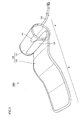
- a cuff for blood pressure monitor 100A is designed based on the intention that a subject him/herself fits the cuff on his/her upper left arm.
- cuff 100A has an inserting portion A for inserting the upper left arm and a fastening portion B for fastening and securing the cuff with respect to the upper arm inserted into inserting portion A.
- a surface of cuff 100A is covered with a cover 130, which is a bag-shaped member made of a cloth.
- cover 130 which is a bag-shaped member made of a cloth.
- cover 130 which is a bag-shaped member made of a cloth.
- cover 130 is a bag-shaped member made of a cloth.
- cover 130 is a bag-shaped member made of a cloth.
- cover 130 is a bag-shaped member made of a cloth.
- cover 130 is a bag-shaped member made of a cloth.
- cover 130 is a bag-shaped member made of a cloth.
- cover 130 is a bag-
- Air bag 120 has a bladder 121.
- Bladder 121 is connected to a rubber tube 152 via a nipple 151.
- Rubber tube 152 is connected to a blood pressure monitor main body (not shown).
- Bladder 121 of air bag 120 is pressurized or depressurized by means of a pressurizing pump, a negative pressure pump and the like incorporated in the blood pressure monitor main body when the blood pressure is measured, and air bag 120 is thereby inflated/deflated.
- Curled elastic member 110 is annularly wound on the outside of air bag 120 so as to surround air bag 120.
- Curled elastic member 110 is formed from a resin member such as polypropylene and thereby adapted to retain its annular state and be changeable in size in a radial direction.
- Curled elastic member 110 has an overlapping region C in which one end 111 and the other end 112 thereof in a circumferential direction are overlapped with each other so that one end 111 is located on an inner side of the other end 112 in a non-fitting state.
- Air bag 120 and curled elastic member 110 are housed inside of cover 130 formed in the bag shape from an outer cloth 131 and an inner cloth 132 which are stitched together.
- a velcro fastener 133 serving as a securing portion for fastening and securing cuff 100A with respect to the upper arm is bonded to or stitched on a predetermined position on an outer peripheral surface of cover 130.
- a sticker 141 as an indicator for showing a spot to be held by hand in the fitting operation is bonded to a surface of outer cloth 131 of cover 130 at a position corresponding to a region D opposing to overlapping region C of curled elastic member 110 and a region closer to one end 111 of curled elastic member 110 than opposing region D.
- sticker 141 is bonded to the surface of cuff 100A such that it is arranged across a position corresponding to one of the circumferential ends of opposing region D that is closer to one end 111 of curled elastic member 110.
- sticker 141 extends on the surface of cuff 100A in a direction intersecting a longitudinal direction of cuff 100A.
- the spot to be held by hand in the fitting operation can be explicitly indicated by sticker 141. Therefore, a user can proceed with a correct fitting operation using sticker 141, which is the indicator, as a mark. As a result, the winding operation of the cuff can be largely facilitated, which enables a correct fitting state to be repeatedly achieved in each measurement. Thus, the blood pressure value can be correctly and stably measured.
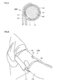
- the user retains cuff 100A for blood pressure monitor so as to sandwich a side part thereof with his/her right hand 220.
- the user places a thumb of right hand 220 on an outer peripheral surface of cuff 100A to thereby cover and hide sticker 141 with the thumb using sticker 141 bonded to the outer peripheral surface of cuff 100A for blood pressure monitor as the mark, and further places the rest of his/her fingers other than the thumb on an inner peripheral surface of cuff 100A.
- the user hitches the other end 112 of curled elastic member 110 on an outer side of an upper arm of his/her left hand 210.
- the user lifts right hand 220 in a direction of an arrow F in the drawing to thereby spread curled elastic member 110 wide and open cuff 100A maintaining the state in which the other end 112 of curled elastic member 110 is hitched on the outer side of the upper arm of left hand 210, and also shifts right hand 220 in a direction of an arrow G in the drawing to thereby fit an end portion of cuff 100A corresponding to one end 111 side of curled elastic member 110 in an inner side of the upper arm of left hand 210, as a result of which a state shown in Fig. 5 arrives.
- the upper arm of left hand 210 can be inserted into inserting portion A of cuff 100A, and further, cuff 100A can be secured to the upper arm of left hand 210 with an appropriate fastening force in response to a radial elasticity retaining force of curled elastic member 110. Then, fastening portion B of cuff 100A is wound around the upper arm of left hand 210 over inserting portion A and fastened and secured with respect to the upper arm by means of velcro fastener 133. In the foregoing manner, a fitting state shown in Fig. 6 is realized.
- a central position of air bag 120 in circumferential and width directions thereof is disposed at a position corresponding to an arterial position on the upper arm of left hand 210 in the fitting state shown in Fig. 6.
- air bag 120 can be inartificially positioned at a suitable position, and the blood pressure value can be thereby accurately and stably measured.
- sticker 141 as the indicator for showing the spot to be held by hand in the fitting operation is bonded to the surface of outer cloth 131 of cover 130 at the position corresponding to region D opposing to overlapping region C of curled elastic member 110 and the region closer to one end 111 of curled elastic member 110 than opposing region D. Therefore, the user can be led to hold cuff 100A using sticker 141 as the mark in the fitting operation, and further, guided to accurately hold a position at which a large bending moment can be obtained.
- Curled elastic member 110 can be thereby greatly changed in size with a small strength in the fitting operation, which enables curled elastic member 110 to be spread with a relatively small strength.
- the fitting operation can be thus more efficiently operable, wherein cuff 100A can be reliably wound and the blood pressure value can be consequently measured in an accurate and stable manner.
- curled elastic member 110 does not have the overlapping region and is provided with a clearance between one end 111 and the other end 112 in the circumferential direction of curled elastic member 110 in the non-fitting state.
- the fitting operation in which the other end 112 of curled elastic member 110 is hitched on the arm and the cuff is wound around the arm while the curled elastic member is spread wide in the hitching state can be carried out in the same manner as in cuff 100A.
- sticker 141 serving as the indicator for showing the spot to be held by hand in the fitting operation is bonded to the surface of outer cloth 131 of cover 130 at a position corresponding to a region closer to one end 111 than a central position E of curled elastic member 110 in the circumferential direction extending from one end 111 to the other end 112 thereof.
- sticker 141 is bonded to the position, the user can be guided to accurately hold the spot at which the large bending moment can be obtained in the fitting operation, and curled elastic member 110 can be thereby spread with a relatively small force.
- cuff 100A' can be reliably wound, which successfully achieves an accurate and stable measurement of the blood pressure value.
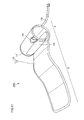
- a cuff 100B for blood pressure monitor according to a second embodiment of the present invention is designed so that the subject can fit the cuff on his/her upper left arm him/herself in the same manner as in cuff 100A according to the first embodiment. Therefore, any component in this embodiment, which is the same as in cuff 100A for blood pressure monitor according to the first embodiment, is simply provided with the same reference numeral and is not described here again.
- cuff 100B for blood pressure monitor according to this embodiment which is different to cuff 100A for blood pressure monitor according to the first embodiment, employs a finger-hitching member 142 formed from elastomer serving as the indicator for showing the spot to be held by hand in the fitting operation.
- finger-hitching member 142 is secured to an outer peripheral surface of curled elastic member 110 by means of an adhesive or the like.
- Outer cloth 131 of cover 130 at a position corresponding to finger-hitching member 142 is slashed so that a surface of finger-hitching member 142 can be exposed.
- finger-hitching member 142 which serves as the indicator for showing the spot to be held by hand in the fitting operation, is attached to a surface of cuff 100B at the position corresponding to region D opposing to overlapping region C of curled elastic member 110 and the region closer to one end 111 of curled elastic member 110 than opposing region D in the non-fitting state.
- Finger-hitching member 142 has a recessed portion 142a so as to increase a fitting property with respect to the thumb of the right hand.
- Cuff 100B can be surely held by hand without causing the slip of the finger in the fitting operation by providing recessed portion 142a on the surface of finger-hitching member 142 as described.
- recessed portion 142a extends in a direction (direction shown in a broken line 180 in Fig. 9) intersecting the circumferential direction of curled elastic member 110 extending from one end 111 to the other end 112 thereof (direction shown with an arrow X in Fig. 9).
- recessed portion 142a is thus provided on the surface at an angle with the longitudinal direction of cuff 100B, cuff 100B can be held in an accurate manner, which further improves the operability in the fitting operation.
- the user can be guided to hold cuff 100B using finger-hitching member 142 as the mark in the fitting operation, which further leads the user to accurately hold the position at which the large bending moment can be obtained in the same manner as in cuff 100A for blood pressure monitor according to the first embodiment.
- curled elastic member 110 can be greatly changed in size with a small force in the fitting operation and thereby spread with a relatively small force.
- the operability in the fitting operation is significantly improved, and the cuff can be correspondingly reliably wound.
- the blood pressure value can be accurately and stably measured.
- the use of the finger-hitching member as the indicator as recited in this embodiment prevents the slip of the finger in contrast to the case of using the sticker, wherein the fitting operation can be further facilitated.
- a cuff 100C for blood pressure monitor according to a third embodiment of the present invention is designed so that the subject can fit the cuff on his/her left upper arm him/herself in the same manner as in cuff 100A according to the first embodiment. Therefore, any component in this embodiment, which is the same as in cuff 100A for blood pressure monitor according to the first embodiment, is simply provided with the same reference numeral and is not described here again.
- cuff 100C for blood pressure monitor according to this embodiment which is different to cuff 100A for blood pressure monitor according to the first embodiment, employs a finger-hitching member 143 having a fingerstall shape and serving as the indicator for showing the spot to be held by hand in the fitting operation.
- Finger-hitching member 143 is attached to, for example, the surface of outer cloth 131 of cover 130 by means of stitching, bonding or the like.
- finger-hitching member 143 having the fingerstall shape which serves as the indicator for showing the spot to be held by hand in the fitting operation, is attached to a surface of cuff 100C at the position corresponding to region D opposing to overlapping region C of curled elastic member 110 and the region closer to one end 111 of curled elastic member 110 than opposing region D in the non-fitting state. Further, as shown in Fig. 11, finger-hitching member 143 having the fingerstall shape extends in a direction intersecting a longitudinal direction of cuff 100C on the surface of cuff 100C.
- finger-hitching member 143 has the fingerstall shape as in the case of cuff 100C for blood pressure monitor according to this embodiment, the finger can be reliably hitched on finger-hitching member 143, and cuff 100C can be unfailingly held by hand without the slip of the finger in the fitting operation.
- the user can be guided to hold cuff 100C using finger-hitching member 143 as the mark in the fitting operation, which further leads the user to accurately hold the position at which the large bending moment can be obtained.
- curled elastic member 110 can be greatly changed in size with a small force and thereby spread with a relatively small force in the fitting operation.
- the operability in the fitting operation is significantly improved, and the cuff can be reliably wound. As a result, the blood pressure value can be accurately and stably measured.
- the use of the finger-hitching member as the indicator as recited in this embodiment prevents the slip of the finger in contrast to the case of using the sticker, wherein the fitting operation can be further facilitated.
- a cuff 100D for blood pressure monitor according to a fourth embodiment of the present invention is designed so that the subject can fit the cuff on his/her left upper arm him/herself in the same manner as in cuff 100A according to the first embodiment. Therefore, any component in this embodiment, which is the same as in cuff 100A for blood pressure monitor according to the first embodiment, is simply provided with the same reference numeral and is not described here again.
- cuff 100D for blood pressure monitor according to the fourth embodiment which is different from cuff 100A for blood pressure monitor according to the first embodiment, employs a grip portion 144 as the indicator for showing the spot to be held in the fitting operation.
- grip portion 144 is secured to the outer peripheral surface of curled elastic member 110 by means of a flat machine screw 144b serving as a securing portion.
- Grip portion 144 has an opening 144a into which the four fingers other than the thumb of the right hand can be inserted.
- grip portion 144 which serves as the indicator for showing the spot to be held by hand in the fitting operation, is attached to a surface of cuff 100D at the position corresponding to region D opposing to overlapping region C of curled elastic member 110 and the region closer to one end 111 of curled elastic member 110 than opposing region D in the non-fitting state.
- the spot to be held by hand in the fitting operation can be explicitly shown by grip portion 144, and the user can thereby follow the accurate fitting operation by holding grip portion 144 as the indicator.
- the winding operation of the cuff can be significantly facilitated, which enables the correct fitting state to be continuously repeated in each measurement.
- the blood pressure value can be thus measured with an accuracy and stability.
- the user inserts the four fingers other than the thumb of right hand 220 into opening 144a of grip portion 144 attached to the surface of cuff 100D for blood pressure monitor to thereby hold grip portion 144, and hitches the other end 112 of curled elastic member 110 on the outer side of the upper arm of left hand 210.
- the user maintains the state in which the other end 112 of curled elastic member 110 is hitched on the outer side of the upper arm of left hand 210, while lifting right hand 220 in a direction of an arrow F to thereby spread curled elastic member 110 wide and open cuff 100D.
- the user shifts right hand 220 in a direction of an arrow G and engages an end portion of cuff 100D corresponding to one end 111 side of curled elastic member 110 with the inner side of the upper arm of left hand 210, as a result of which a state shown in Fig. 18 is generated.
- the upper arm of left hand 210 can be inserted into inserting portion A of cuff 100D, and cuff 100D can be secured to the upper arm of left hand 210 with an appropriate fastening force in response to the radial elasticity retaining force of curled elastic member 110. Then, fastening portion B of cuff 100D is wound around the upper arm of left hand 210 over inserting portion A and fastened and secured with respect to the upper arm by means of velcro fastener 133 mentioned earlier. In the foregoing manner, a fitting state shown in Fig. 19 can be realized.
- the user inserts the four fingers other than the thumb of right hand 220 into opening 144a of grip portion 144 attached to the surface of cuff 100D for blood pressure monitor to thereby hold grip portion 144 and places right hand 220 on cuff 100D so that a palm of right hand 220 faces the outer peripheral surface of cuff 100D.
- the user hitches the other end 112 of curled elastic member 110 on the outer side of the upper arm of left hand 210.
- the user maintains the state in which the other end 112 of curled elastic member 110 is hitched on the outer side of the upper arm of left hand 210, while lifting right hand 220 in a direction of an arrow F to thereby spread curled elastic member 110 wide and open cuff 100D.
- the user shifts right hand 220 in a direction of an arrow G and engages the end portion of cuff 100D corresponding to one end 111 side of curled elastic member 110 with the inner side of the upper arm of left hand 210, as a result of which the state shown in Fig. 22 is generated.
- the upper arm of left hand 210 can be inserted into inserting portion A of cuff 100D, and cuff 100D can be secured to the upper arm of left hand 210 with an appropriate fastening force in response to the radial elasticity retaining force of curled elastic member 110. Then, fastening portion B of cuff 100D is wound around the upper arm of left hand 210 over inserting portion A and fastened and secured with respect to the upper arm by means of velcro fastener 133 mentioned earlier. In the foregoing manner, the fitting state shown in Fig. 19 can be realized.
- the central position in the circumferential and width directions of air bag 120 is disposed at the position corresponding to the arterial position on the upper arm of left hand 210 in the fitting state shown in Fig. 19.
- air bag 120 can be inartificially positioned at an appropriate position enabling the blood pressure value to be accurately and stably measured.
- grip portion 144 which serves as the indicator for showing the spot to be held by hand in the fitting operation, is provided on the surface of outer cloth 131 of cover 130 at the position corresponding to region D opposing to overlapping region C of curled elastic member 110 and the region closer to one end 111 of curled elastic member 110 than opposing region D in the non-fitting state. Accordingly, the user can be led to hold grip portion 144 in the fitting operation and further led to accurately hold the position at which the large bending moment can be obtained. Therefore, curled elastic member 110 can be greatly changed in size with a small force in the fitting operation and can be consequently spread with a relatively small force. The cuff can be then reliably wound along with the dramatically improved operability in the fitting operation, as a result of which the blood pressure value can be accurately and stably measured.
- a cuff 100E for blood pressure monitor according to a fifth embodiment of the present invention is designed in such manner that the subject can fit the cuff on his/her left upper arm him/herself in the same manner as in cuff 100D according to the fourth embodiment. Therefore, any component in this embodiment, which is the same as in cuff 100D for blood pressure monitor according to the fourth embodiment, is simply provided with the same reference numeral and is not described here again.
- cuff for blood pressure monitor 100E includes grip portion 144, which serves as the indicator for showing the spot to be held by hand in the fitting operation, on a surface thereof in the same manner as in cuff for blood pressure monitor 100D according to the fourth embodiment.
- Cuff 100E for blood pressure monitor according to this embodiment further includes a bending portion 113 at a predetermined position on the other end 112 side relative to a position where grip portion 144 is provided in curled elastic member 110, which does not conform to the constitution of cuff 100D for blood pressure monitor according to the fourth embodiment. More specifically, grip portion 144 is disposed on one end 111 side relative to bending portion 113 in the circumferential direction of curled elastic member 110.
- Bending portion 113 is a portion arranged to be more easily bendable than any other part of curled elastic member 110.
- bending portion 113 is formed from a notch provided in the outer peripheral surface of curled elastic member 110.
- the user inserts the four fingers other than the thumb of right hand 220 into opening 144a of grip portion 144 attached to the surface of cuff for blood pressure monitor 100E to thereby hold grip portion 144, and hitches the other end 112 of curled elastic member 110 on the outer side of the upper arm of left hand 210.
- curled elastic member 110 is largely bent at bending portion 113 by a small force applied to grip portion 144, and cuff 100E is consequently opened wide as shown in the drawing.
- the user maintains the state in which the other end 112 of curled elastic member 110 is hitched on the outer side of the upper arm of left hand 210, while shifting right hand 220 downward in a direction of an arrow H to thereby engages an end portion of cuff 100E with the inner side of the upper arm of left hand 210.
- the upper arm of left hand 210 can be inserted into inserting portion A of cuff 100E, and cuff 100E can be secured to the upper arm of left hand 210 with an appropriate fastening force in response to the radial elasticity retaining force of curled elastic member 110. Then, fastening portion B of cuff 100E is wound around the upper arm of left hand 210 over inserting portion A and fastened and secured with respect to the upper arm by means of velcro fastener 133 mentioned earlier. In the foregoing manner, a fitting state, which conforms to the fitting state according to the fourth embodiment shown in Fig. 19, can be realized.
- curled elastic member 110 can be spread wide with a small force when the other end 112 of curled elastic member 110 is hitched on the outer side part of the left arm because bending portion 113 is more easily bendable than any other part of curled elastic member 110 as described earlier. As a result, the winding operation of the cuff is largely facilitated, and the correct fitting state can be repeatedly achieved in each measurement. The blood pressure value can be thereby accurately and stably measured.
- bending portion 113 may be formed from the thinned portion resulting from the notch made into curled elastic member 110 as described or formed from a slit provided in the width direction of curled elastic member 110.
- bending portion 113 may be constituted in such manner that curled elastic member 110 is divided into two parts which are connected by an elastic member such as a spring, or may be designed in such manner that curled elastic member 110 is left unprocessed and grip portion 144 is formed from a member having a larger rigidity than that of curled elastic member 110 so that curled elastic member 110 can be locally bent at an edge of the part where grip portion 144 is attached to curled elastic member 110.
- the sticker, finger-hitching member, grip portion and the like were described as the examples of the indicator, however, the present invention is not limited to the mentioned examples.
- the indicator can be arranged in such manner that the surface of the cover is colored differently to the other parts, or an additional cloth material is stitched to constitute the indicator. Any indicator merely capable of informing the user of the spot to be held by hand in the fitting operation can be adopted.
- sticker 141, finger-hitching members 142 and 143, and grip portion 144 serving as the indicator for showing the spot to be held by hand in the fitting operation are respectively provided on the surface of the cuff at the position corresponding to region D opposing to overlapping region C of curled elastic member 110 and the region closer to one end 111 of curled elastic member 110 than opposing region D.
- sticker 141, finger-hitching members 142 and 143 and grip portion 144 as the indicator may be respectively provided on the surface of outer cloth 131 of cover 130 only at the position corresponding to region D opposing to overlapping region C of curled elastic member 110.
- sticker 141, finger-hitching members 142 and 143 and grip portion 144 as the indicator may be respectively provided on the surface of outer cloth 131 of cover 130 only at the position corresponding to the region closer to one end 111 of curled elastic member 110 than opposing region D. Further, sticker 141, finger-hitching members 142 and 143 and grip portion 144 as the indicator are preferably provided on the surface of outer cloth 131 of cover 130 at the position corresponding to the region closer to one end 111 than central position E (see Figs. 2, 10, 12 and 14) in the circumferential direction of curled elastic member 110 extending from one end 111 to the other end 112 thereof.
- the second to fifth embodiments were described referring to the curled elastic member having the overlapping region in which the circumferential one end and the other end are overlapped with each other in the non-fitting state.
- the one end and the other end are not necessarily overlapped with each other, and the present invention can be applied to the constitution in which the clearance for inserting the arm is provided between the one end and the other end in the circumferential direction in the non-fitting state as recited in the description of cuff 100A' for blood pressure monitor (see Fig. 7), which was introduced as a modification example in the first embodiment.
- the first to fifth embodiments were described based on the cuff for blood pressure monitor designed in such manner that the cuff is wound around the upper arm of the left hand.
- the cuff may be designed in such manner as to be wound around the upper arm of the right hand.
- the cuff is not necessarily wound around the upper arm, and can be naturally designed for application to a forearm, wrist, lower extremity or the like.
Landscapes
- Health & Medical Sciences (AREA)
- Life Sciences & Earth Sciences (AREA)
- Cardiology (AREA)
- Vascular Medicine (AREA)
- Engineering & Computer Science (AREA)
- Medical Informatics (AREA)
- Physics & Mathematics (AREA)
- Ophthalmology & Optometry (AREA)
- Biophysics (AREA)
- Pathology (AREA)
- Veterinary Medicine (AREA)
- Biomedical Technology (AREA)
- Heart & Thoracic Surgery (AREA)
- Physiology (AREA)
- Molecular Biology (AREA)
- Surgery (AREA)
- Animal Behavior & Ethology (AREA)
- General Health & Medical Sciences (AREA)
- Public Health (AREA)
- Dentistry (AREA)
- Measuring Pulse, Heart Rate, Blood Pressure Or Blood Flow (AREA)
Abstract
Description
Claims (19)
- A cuff for blood pressure monitor wound around a living body to be fitted thereon, comprising:a fluid bag (120) for pressing the living body;an elastic member (110) wound annularly on the outside of said fluid bag (120) and changeable in size in a radial direction; anda cover (130) having a bag shape for including said fluid bag (120) and said elastic member (110), whereinsaid elastic member (110) has an overlapping region (C) in which one end (111) and the other end (112) thereof in a circumferential direction are overlapped with each other so that said one end (111) is located on an inner side of said other end (112) in a non-fitting state, andan indicator for showing a spot to be held by hand in the fitting operation is provided at a position corresponding to a region (D) opposing to said overlapping region (C) of said elastic member (110) and/or a region closer to said one end (111) of said elastic member (110) than the opposing region (D) in the non-fitting state.
- The cuff for blood pressure monitor according to claim 1, wherein
a sticker (141) bonded to a surface of said cuff constitutes said indicator. - The cuff for blood pressure monitor according to claim 1, wherein finger-hitching members (142, 143) attached to a surface of said cuff constitute said indicator.
- The cuff for blood pressure monitor according to claim 3, wherein
said finger-hitching member (142) has a recessed portion (142a) for receiving a finger in a surface thereof. - The cuff for blood pressure monitor according to claim 4, wherein
said recessed portion (142a) extends in a direction intersecting the circumferential direction of said elastic member (110) extending from said one end (111) to said other end (112) thereof. - The cuff for blood pressure monitor according to claim 3, wherein
said finger-hitching member (143) has a fingerstall shape. - The cuff for blood pressure monitor according to claim 3, wherein
said finger-hitching members (142, 143) are formed from elastomer. - The cuff for blood pressure monitor according to claim 1, wherein
a grip portion (144) attached to a surface of said cuff constitutes said indicator. - A cuff for blood pressure monitor wound around a living body to be fitted thereon, comprising:a fluid bag (120) for pressing the living body;an elastic member (110) wound annularly on the outside of said fluid bag (120) and having one end (111) and the other end (112) thereof in a circumferential direction, said elastic member being changeable in size in a radial direction; anda cover (130) having a bag shape for including said fluid bag (120) and said elastic member (110), whereinan indicator for showing a spot to be held by hand in the fitting operation is provided at a position corresponding to a region closer to said one end (111) of said elastic member (110) than a central position (E) thereof in the circumferential direction extending from said one end (111) to said other end (112).
- The cuff for blood pressure monitor according to claim 9, wherein
a sticker (141) bonded to a surface of said cuff constitutes said indicator. - The cuff for blood pressure monitor according to claim 9, wherein
finger-hitching members (142, 143) attached to a surface of said cuff constitute said indicator. - The cuff for blood pressure monitor according to claim 11, wherein
said finger-hitching member (142) has a recessed portion (142a) for receiving a finger in a surface thereof. - The cuff for blood pressure monitor according to claim 12, wherein
said recessed portion (142a) extends in a direction intersecting the circumferential direction of said elastic member (110) extending from said one end (111) to said other end (112) thereof. - The cuff for blood pressure monitor according to claim 11, wherein
said finger-hitching member (143) has a fingerstall shape. - The cuff for blood pressure monitor according to claim 9, wherein a grip portion (144) attached to a surface of said cuff constitutes said indicator.
- A cuff for blood pressure monitor wound around a living body to be fitted thereon, comprising:a fluid bag (120) for pressing the living body;an elastic member (110) wound annularly on the outside of said fluid bag (120) and having one end (111) and the other end (112) thereof in a circumferential direction, said elastic member being changeable in size in a radial direction; anda cover (130) having a bag shape for including said fluid bag (120) and said elastic member (110), whereinsaid elastic member (110) has a bendable bending portion (113), andan indicator for showing a spot to be held by hand in the fitting operation is provided at a position corresponding to a region closer to said one end (111) of said elastic member (110) than said bending portion (113) of said elastic member (110).
- The cuff for blood pressure monitor according to claim 16, wherein
a sticker (141) bonded to a surface of said cuff constitutes said indicator. - The cuff for blood pressure monitor according to claim 16, wherein
finger-hitching members (142, 143) attached to a surface of said cuff constitute said indicator. - The cuff for blood pressure monitor according to claim 16, wherein
a grip portion (144) attached to a surface of said cuff constitutes said indicator.
Applications Claiming Priority (2)
| Application Number | Priority Date | Filing Date | Title |
|---|---|---|---|
| JP2004138923 | 2004-05-07 | ||
| JP2004138923A JP4534583B2 (en) | 2004-05-07 | 2004-05-07 | Sphygmomanometer cuff |
Publications (2)
| Publication Number | Publication Date |
|---|---|
| EP1593340A1 true EP1593340A1 (en) | 2005-11-09 |
| EP1593340B1 EP1593340B1 (en) | 2011-08-10 |
Family
ID=34936097
Family Applications (1)
| Application Number | Title | Priority Date | Filing Date |
|---|---|---|---|
| EP05009712A Expired - Lifetime EP1593340B1 (en) | 2004-05-07 | 2005-05-03 | Cuff for blood pressure monitor |
Country Status (5)
| Country | Link |
|---|---|
| US (1) | US20050251052A1 (en) |
| EP (1) | EP1593340B1 (en) |
| JP (1) | JP4534583B2 (en) |
| KR (1) | KR100638699B1 (en) |
| CN (1) | CN100340209C (en) |
Cited By (4)
| Publication number | Priority date | Publication date | Assignee | Title |
|---|---|---|---|---|
| EP2258260A1 (en) * | 2009-06-04 | 2010-12-08 | Panasonic Electric Works Co., Ltd. | Blood pressure cuff |
| CN102813509A (en) * | 2012-09-14 | 2012-12-12 | 天津九安医疗电子股份有限公司 | Sphygmomanometer cuff and manufacturing method thereof as well as sphygmomanometer using cuff |
| CN101909517B (en) * | 2007-12-28 | 2013-04-24 | 欧姆龙健康医疗事业株式会社 | Sphygmomanometer cuff and sphygmomanometer |
| CN119344697A (en) * | 2024-10-23 | 2025-01-24 | 广东医群科技有限公司 | A remote medical examination device for patient diagnosis |
Families Citing this family (18)
| Publication number | Priority date | Publication date | Assignee | Title |
|---|---|---|---|---|
| JP4665757B2 (en) * | 2005-12-27 | 2011-04-06 | オムロンヘルスケア株式会社 | Sphygmomanometer cuff and sphygmomanometer equipped with the same |
| JP5101897B2 (en) * | 2007-01-24 | 2012-12-19 | テルモ株式会社 | Blood pressure measuring device, cuff and cuff manufacturing method |
| JP2010000123A (en) * | 2008-06-18 | 2010-01-07 | Omron Healthcare Co Ltd | Auxiliary device for winding cuff band |
| JP5405860B2 (en) * | 2009-03-18 | 2014-02-05 | テルモ株式会社 | Sphygmomanometer |
| JP5335498B2 (en) * | 2009-03-18 | 2013-11-06 | テルモ株式会社 | Sphygmomanometer |
| KR101034390B1 (en) | 2009-09-21 | 2011-05-16 | 주식회사 바이오스페이스 | Cuff for Sphygmomanometer |
| DE102011111030A1 (en) * | 2010-12-24 | 2012-06-28 | Paul Hartmann Ag | Blood pressure measuring cuff |
| DE102010056241A1 (en) * | 2010-12-24 | 2012-06-28 | Paul Hartmann Ag | Blood pressure measuring cuff |
| DE102011115186A1 (en) * | 2011-09-28 | 2013-03-28 | Paul Hartmann Ag | Wrap cuff for measuring blood pressure |
| JP6139871B2 (en) * | 2012-12-07 | 2017-05-31 | 株式会社エー・アンド・デイ | Sphygmomanometer cuff |
| WO2014121805A1 (en) | 2013-02-08 | 2014-08-14 | Up-Med Gmbh | Blood pressure measuring system comprising a kinking-proof shell |
| CN106108873A (en) * | 2016-06-12 | 2016-11-16 | 江苏鱼跃医疗设备股份有限公司 | A kind of measurement blood pressure cuff |
| CN105919580B (en) * | 2016-06-13 | 2019-07-09 | 江苏鱼跃信息系统有限公司 | A kind of cuff for sphygmomanometers |
| JP6852446B2 (en) * | 2017-02-16 | 2021-03-31 | オムロンヘルスケア株式会社 | Blood pressure information measuring device |
| DE102018006845B4 (en) * | 2018-08-29 | 2020-04-16 | Pulsion Medical Systems Se | Non-invasive blood pressure measuring device |
| JP7661264B2 (en) | 2022-03-16 | 2025-04-14 | シチズン時計株式会社 | Sphygmomanometer arm band |
| JP7741055B2 (en) * | 2022-12-19 | 2025-09-17 | シチズン時計株式会社 | Soft cuff application aid |
| US20250352077A1 (en) * | 2024-05-14 | 2025-11-20 | K-Jump Health Co., Ltd. | Blood pressure measuring device capable of measuring meridians |
Citations (5)
| Publication number | Priority date | Publication date | Assignee | Title |
|---|---|---|---|---|
| US3517661A (en) * | 1967-04-24 | 1970-06-30 | Picker Corp | Differential plethysmography |
| US3906937A (en) * | 1972-10-25 | 1975-09-23 | Para Medical Instr Corp | Blood pressure cuff and bladder and apparatus embodying the same |
| JPS61238229A (en) | 1985-04-13 | 1986-10-23 | 松下電工株式会社 | Cuff band of hemomanometer |
| EP1224907A2 (en) * | 2001-01-23 | 2002-07-24 | Omron Corporation | Cuff for blood pressure monitor |
| JP2003210423A (en) | 2002-01-24 | 2003-07-29 | A & D Co Ltd | Core for sphygmomanometer cuff |
Family Cites Families (15)
| Publication number | Priority date | Publication date | Assignee | Title |
|---|---|---|---|---|
| US2320179A (en) * | 1942-09-23 | 1943-05-25 | Richard B Gray | Sphygmomanometer cuff or band |
| US3699945A (en) * | 1970-07-30 | 1972-10-24 | Paul M Hanafin | Blood pressure cuff with calibrated holding means |
| JPS5951838A (en) * | 1982-09-20 | 1984-03-26 | 松下電工株式会社 | Cuff band of hemomanometer |
| US4716906A (en) * | 1986-06-30 | 1988-01-05 | Spacelabs, Inc. | Blood pressure cuff |
| US4727885A (en) * | 1986-12-24 | 1988-03-01 | Spacelabs, Inc. | Self applied blood pressure cuff |
| US4832040A (en) * | 1987-07-22 | 1989-05-23 | Spacelabs, Inc. | Non-bunching cinch ring for self-applied blood pressure cuff |
| JP2852093B2 (en) * | 1990-01-26 | 1999-01-27 | 松下電工株式会社 | Sphygmomanometer |
| US5176129A (en) * | 1991-03-01 | 1993-01-05 | Tekdyne, Inc. | Self-retaining refractor |
| JPH07124127A (en) * | 1993-06-18 | 1995-05-16 | Omron Corp | Armband for sphygmomanometer |
| US5897503A (en) * | 1997-08-01 | 1999-04-27 | Acuson Corporation | Ultrasound transducer probe having case handle grip surfaces |
| US6152881A (en) * | 1999-03-29 | 2000-11-28 | Vasocor, Inc. | Calibrated measurement of blood vessels and endothelium after reactive hyperemia and method therefor |
| US6245024B1 (en) * | 2000-01-13 | 2001-06-12 | Sunbeam Products, Inc. | Blood pressure cuff with tension indicator |
| JP3622730B2 (en) * | 2002-02-04 | 2005-02-23 | オムロンヘルスケア株式会社 | Sphygmomanometer arm band |
| US20040049114A1 (en) * | 2002-08-30 | 2004-03-11 | Ethox Corporation | Enclosure for a blood pressure cuff |
| JP2004201741A (en) * | 2002-12-24 | 2004-07-22 | Terumo Corp | Cuff for tonometer |
-
2004
- 2004-05-07 JP JP2004138923A patent/JP4534583B2/en not_active Expired - Lifetime
-
2005
- 2005-04-28 US US11/116,453 patent/US20050251052A1/en not_active Abandoned
- 2005-05-03 EP EP05009712A patent/EP1593340B1/en not_active Expired - Lifetime
- 2005-05-06 KR KR1020050038021A patent/KR100638699B1/en not_active Expired - Fee Related
- 2005-05-08 CN CNB2005100697083A patent/CN100340209C/en not_active Expired - Lifetime
Patent Citations (6)
| Publication number | Priority date | Publication date | Assignee | Title |
|---|---|---|---|---|
| US3517661A (en) * | 1967-04-24 | 1970-06-30 | Picker Corp | Differential plethysmography |
| US3906937A (en) * | 1972-10-25 | 1975-09-23 | Para Medical Instr Corp | Blood pressure cuff and bladder and apparatus embodying the same |
| JPS61238229A (en) | 1985-04-13 | 1986-10-23 | 松下電工株式会社 | Cuff band of hemomanometer |
| EP1224907A2 (en) * | 2001-01-23 | 2002-07-24 | Omron Corporation | Cuff for blood pressure monitor |
| JP2002209858A (en) | 2001-01-23 | 2002-07-30 | Omron Corp | Sphygmomanometer cuff |
| JP2003210423A (en) | 2002-01-24 | 2003-07-29 | A & D Co Ltd | Core for sphygmomanometer cuff |
Cited By (4)
| Publication number | Priority date | Publication date | Assignee | Title |
|---|---|---|---|---|
| CN101909517B (en) * | 2007-12-28 | 2013-04-24 | 欧姆龙健康医疗事业株式会社 | Sphygmomanometer cuff and sphygmomanometer |
| EP2258260A1 (en) * | 2009-06-04 | 2010-12-08 | Panasonic Electric Works Co., Ltd. | Blood pressure cuff |
| CN102813509A (en) * | 2012-09-14 | 2012-12-12 | 天津九安医疗电子股份有限公司 | Sphygmomanometer cuff and manufacturing method thereof as well as sphygmomanometer using cuff |
| CN119344697A (en) * | 2024-10-23 | 2025-01-24 | 广东医群科技有限公司 | A remote medical examination device for patient diagnosis |
Also Published As
| Publication number | Publication date |
|---|---|
| KR100638699B1 (en) | 2006-10-30 |
| EP1593340B1 (en) | 2011-08-10 |
| JP4534583B2 (en) | 2010-09-01 |
| KR20060045930A (en) | 2006-05-17 |
| JP2005319030A (en) | 2005-11-17 |
| US20050251052A1 (en) | 2005-11-10 |
| CN1692876A (en) | 2005-11-09 |
| CN100340209C (en) | 2007-10-03 |
Similar Documents
| Publication | Publication Date | Title |
|---|---|---|
| EP1593340B1 (en) | Cuff for blood pressure monitor | |
| US20060047206A1 (en) | Cuff for blood pressure monitor | |
| JP5175846B2 (en) | Apparatus and method for non-invasively measuring hemodynamic parameters | |
| US20050080345A1 (en) | Apparatus and methods for non-invasively measuring hemodynamic parameters | |
| EP2002785A2 (en) | Blood pressure measurement device | |
| JP3159862U (en) | Sphygmomanometer cuff | |
| US20060184051A1 (en) | Apparatus and methods for non-invasively measuring hemodynamic parameters | |
| JP2006501966A (en) | Non-invasive measurement of hemodynamic parameters | |
| WO2007119482A1 (en) | Sphygmomanometers cuff | |
| US20230000372A1 (en) | Cuff structure and blood pressure measurement device | |
| KR100957298B1 (en) | Biometric Information Measuring Device | |
| US20240197189A1 (en) | Biological information measurement device | |
| CN103281956B (en) | Blood pressure measurement ties up cover | |
| JP2669858B2 (en) | Wrist sphygmomanometer | |
| JPWO2004080299A1 (en) | Sphygmomanometer cuff and sphygmomanometer equipped therewith | |
| JP4237194B2 (en) | Armband for sphygmomanometer | |
| JP7556200B2 (en) | Cuff structure and blood pressure measuring device | |
| JP2013034791A (en) | Cuff for sphygmomanometer | |
| JP5208656B2 (en) | Biological compression device and blood pressure measurement device | |
| US20240180437A1 (en) | Blood pressure measurement device | |
| EP3808260B1 (en) | Sphygmomanometer arm band and control method thereof | |
| JP6139871B2 (en) | Sphygmomanometer cuff | |
| JP3692121B2 (en) | Pressure band for blood pressure measurement | |
| CN119156170A (en) | Wrist sphygmomanometer | |
| JP2004267469A (en) | Blood pressure measuring cuff |
Legal Events
| Date | Code | Title | Description |
|---|---|---|---|
| PUAI | Public reference made under article 153(3) epc to a published international application that has entered the european phase |
Free format text: ORIGINAL CODE: 0009012 |
|
| 17P | Request for examination filed |
Effective date: 20050915 |
|
| AK | Designated contracting states |
Kind code of ref document: A1 Designated state(s): AT BE BG CH CY CZ DE DK EE ES FI FR GB GR HU IE IS IT LI LT LU MC NL PL PT RO SE SI SK TR |
|
| AX | Request for extension of the european patent |
Extension state: AL BA HR LV MK YU |
|
| AKX | Designation fees paid |
Designated state(s): DE ES FR GB IT |
|
| 17Q | First examination report despatched |
Effective date: 20070215 |
|
| GRAP | Despatch of communication of intention to grant a patent |
Free format text: ORIGINAL CODE: EPIDOSNIGR1 |
|
| GRAS | Grant fee paid |
Free format text: ORIGINAL CODE: EPIDOSNIGR3 |
|
| GRAA | (expected) grant |
Free format text: ORIGINAL CODE: 0009210 |
|
| AK | Designated contracting states |
Kind code of ref document: B1 Designated state(s): DE ES FR GB IT |
|
| REG | Reference to a national code |
Ref country code: GB Ref legal event code: FG4D |
|
| REG | Reference to a national code |
Ref country code: DE Ref legal event code: R096 Ref document number: 602005029380 Country of ref document: DE Effective date: 20111013 |
|
| PG25 | Lapsed in a contracting state [announced via postgrant information from national office to epo] |
Ref country code: IT Free format text: LAPSE BECAUSE OF FAILURE TO SUBMIT A TRANSLATION OF THE DESCRIPTION OR TO PAY THE FEE WITHIN THE PRESCRIBED TIME-LIMIT Effective date: 20110810 |
|
| PLBE | No opposition filed within time limit |
Free format text: ORIGINAL CODE: 0009261 |
|
| STAA | Information on the status of an ep patent application or granted ep patent |
Free format text: STATUS: NO OPPOSITION FILED WITHIN TIME LIMIT |
|
| 26N | No opposition filed |
Effective date: 20120511 |
|
| REG | Reference to a national code |
Ref country code: DE Ref legal event code: R097 Ref document number: 602005029380 Country of ref document: DE Effective date: 20120511 |
|
| GBPC | Gb: european patent ceased through non-payment of renewal fee |
Effective date: 20120503 |
|
| REG | Reference to a national code |
Ref country code: DE Ref legal event code: R082 Ref document number: 602005029380 Country of ref document: DE Representative=s name: KILIAN KILIAN & PARTNER MBB PATENTANWAELTE, DE Ref country code: DE Ref legal event code: R082 Ref document number: 602005029380 Country of ref document: DE Representative=s name: KILIAN KILIAN & PARTNER, DE |
|
| REG | Reference to a national code |
Ref country code: FR Ref legal event code: ST Effective date: 20130131 |
|
| PG25 | Lapsed in a contracting state [announced via postgrant information from national office to epo] |
Ref country code: FR Free format text: LAPSE BECAUSE OF NON-PAYMENT OF DUE FEES Effective date: 20120531 Ref country code: GB Free format text: LAPSE BECAUSE OF NON-PAYMENT OF DUE FEES Effective date: 20120503 Ref country code: ES Free format text: LAPSE BECAUSE OF FAILURE TO SUBMIT A TRANSLATION OF THE DESCRIPTION OR TO PAY THE FEE WITHIN THE PRESCRIBED TIME-LIMIT Effective date: 20111121 |
|
| P01 | Opt-out of the competence of the unified patent court (upc) registered |
Effective date: 20230512 |
|
| PGFP | Annual fee paid to national office [announced via postgrant information from national office to epo] |
Ref country code: DE Payment date: 20240522 Year of fee payment: 20 |
|
| REG | Reference to a national code |
Ref country code: DE Ref legal event code: R071 Ref document number: 602005029380 Country of ref document: DE |