EP1593017B1 - Messung des packetverlustverhältnisses in einem netzwerk unter verwendung von endpunktdaten - Google Patents
Messung des packetverlustverhältnisses in einem netzwerk unter verwendung von endpunktdaten Download PDFInfo
- Publication number
- EP1593017B1 EP1593017B1 EP04706027A EP04706027A EP1593017B1 EP 1593017 B1 EP1593017 B1 EP 1593017B1 EP 04706027 A EP04706027 A EP 04706027A EP 04706027 A EP04706027 A EP 04706027A EP 1593017 B1 EP1593017 B1 EP 1593017B1
- Authority
- EP
- European Patent Office
- Prior art keywords
- data
- network
- filtered
- difference signal
- standard deviation
- Prior art date
- Legal status (The legal status is an assumption and is not a legal conclusion. Google has not performed a legal analysis and makes no representation as to the accuracy of the status listed.)
- Expired - Lifetime
Links
- 238000005259 measurement Methods 0.000 title description 19
- 238000000034 method Methods 0.000 claims description 64
- 238000005070 sampling Methods 0.000 claims description 12
- 239000000523 sample Substances 0.000 description 23
- 230000008569 process Effects 0.000 description 15
- 238000010586 diagram Methods 0.000 description 7
- 238000001514 detection method Methods 0.000 description 6
- 238000009434 installation Methods 0.000 description 5
- 238000012545 processing Methods 0.000 description 5
- 238000012935 Averaging Methods 0.000 description 4
- 241001125929 Trisopterus luscus Species 0.000 description 4
- 238000004422 calculation algorithm Methods 0.000 description 4
- 238000004891 communication Methods 0.000 description 4
- 230000004931 aggregating effect Effects 0.000 description 2
- 238000004364 calculation method Methods 0.000 description 2
- 230000008859 change Effects 0.000 description 2
- 238000004590 computer program Methods 0.000 description 2
- 238000012937 correction Methods 0.000 description 2
- 238000013480 data collection Methods 0.000 description 2
- 238000001914 filtration Methods 0.000 description 2
- 230000010354 integration Effects 0.000 description 2
- 238000012986 modification Methods 0.000 description 2
- 230000004048 modification Effects 0.000 description 2
- 238000007781 pre-processing Methods 0.000 description 2
- 230000035945 sensitivity Effects 0.000 description 2
- 238000012360 testing method Methods 0.000 description 2
- 230000006727 cell loss Effects 0.000 description 1
- 238000006073 displacement reaction Methods 0.000 description 1
- 230000006870 function Effects 0.000 description 1
- 238000009499 grossing Methods 0.000 description 1
- 238000012544 monitoring process Methods 0.000 description 1
- 238000002360 preparation method Methods 0.000 description 1
- 230000009467 reduction Effects 0.000 description 1
- 238000001228 spectrum Methods 0.000 description 1
- 238000012546 transfer Methods 0.000 description 1
- 230000003245 working effect Effects 0.000 description 1
Images




Classifications
-
- H—ELECTRICITY
- H04—ELECTRIC COMMUNICATION TECHNIQUE
- H04L—TRANSMISSION OF DIGITAL INFORMATION, e.g. TELEGRAPHIC COMMUNICATION
- H04L69/00—Network arrangements, protocols or services independent of the application payload and not provided for in the other groups of this subclass
- H04L69/30—Definitions, standards or architectural aspects of layered protocol stacks
- H04L69/32—Architecture of open systems interconnection [OSI] 7-layer type protocol stacks, e.g. the interfaces between the data link level and the physical level
- H04L69/322—Intralayer communication protocols among peer entities or protocol data unit [PDU] definitions
- H04L69/323—Intralayer communication protocols among peer entities or protocol data unit [PDU] definitions in the physical layer [OSI layer 1]
-
- H—ELECTRICITY
- H04—ELECTRIC COMMUNICATION TECHNIQUE
- H04L—TRANSMISSION OF DIGITAL INFORMATION, e.g. TELEGRAPHIC COMMUNICATION
- H04L69/00—Network arrangements, protocols or services independent of the application payload and not provided for in the other groups of this subclass
- H04L69/30—Definitions, standards or architectural aspects of layered protocol stacks
- H04L69/32—Architecture of open systems interconnection [OSI] 7-layer type protocol stacks, e.g. the interfaces between the data link level and the physical level
- H04L69/322—Intralayer communication protocols among peer entities or protocol data unit [PDU] definitions
- H04L69/324—Intralayer communication protocols among peer entities or protocol data unit [PDU] definitions in the data link layer [OSI layer 2], e.g. HDLC
Definitions
- This invention is related to a method and system for the measurement of the packet loss ratio (PLR) in a packet-based network whether an Internet protocol (IP), asynchronous transfer mode (ATM), frame relay (FR) or multi-protocol label switching (MPLS) network or a virtual private network (VPN).
- PLR packet loss ratio
- IP Internet protocol
- ATM asynchronous transfer mode
- FR frame relay
- MPLS multi-protocol label switching
- VPN virtual private network
- PLR packet loss ratio
- SLA Service Level Agreement
- Probes may be either active or passive. In either case they require the installation of dedicated equipment in strategic locations such as central offices. Such installations are costly. Additional installations are required as the network grows. In other words, the use of probes is not inherently scalable.
- the second existing method of measuring packet loss requires the collection of hop-by-hop measurements. This requires detailed topology information and also requires cooperation of intermediate network operators. The packets may traverse networks that are owned by competing entities and one operator may not be willing to provide the hop-by-hop data necessary to measure the PLR.
- the present invention provides a method and system for measuring packet (cell, data) loss rates in a network without the use of hardware or software probes.
- the present inventive system and method uses only ingress and egress network element traffic information, such as packet count or byte count for a specific channel (see also document US-A 6 188 674 ).
- the procedure may also be used in virtual private networks (VPNs).
- the method and system use data on packet counts or byte counts at the ingress and egress network elements (or at all edge network elements in the case of a VPN). This counter data is preprocessed to complete missing data, calculate differences per collection interval to generate a data difference signal, make corrections for header size variations in the case of byte count data, remove undesirable variations and adjust for network element failure to update counters.
- the data difference signal is sent through a low pass filter of one or more tap sizes and may be integrated.
- the standard deviation of the filtered and/or integrated data within a period of time before a predetermined window is determined. If the data loss rate calculated within the predetermined window is greater than a detectability threshold based on the computed standard deviation then the process has measured a detectable loss within the window. If the loss is measurable the loss rate is reported.
- FIG. 1 depicts a typical network in which the packet loss ratio measurement system and method of the present invention can be utilized.
- Network elements consisting of ingress network element 110 and egress network element 120 are connected to a network 100 that may consist of any number of other network elements.
- a network element may be any type of packet switch, router, ATM device or other element, which is capable of transmitting packets or bytes of data in the format and protocol specific to the type of network 100 whether it is ATM, IP, FR or MPLS.
- the packet loss ratio measurement system (PLRMS) 130 contains the novel aspects of the present invention in which the data required to determine the packet loss ratio is sent in order to perform the calculations set forth below. The exact workings of the PLRMS 130 will be described below.
- the present invention enables the detection of data loss in the network for a specific channel using only packet count (or byte count) data from the ingress and egress network elements (NEs). Data may travel through any number of other network elements as it is transported across the network but packet loss data may or may not be available from these intermediate network elements or the data collection systems choose to collect edge data only.
- This disclosure describes the process to determine packet loss in one direction of the communications channel the other direction is treated separately in the same way.
- the packet counts, or byte counts, at the ingress and egress refer to one communication channel where all packets at the ingress must go out at the egress, under no loss conditions.
- the network must not add any data to the channel, or remove data from the channel.
- the method of the present invention can correct for header size change and still apply the method to measure user traffic loss in the network.
- the path the data takes through the network is unimportant, different data packets may even take different routes. It only matters that the ingress and egress points are the same for all user data.
- the packet and byte counts are usually sampled at equally spaced intervals at the ingress and egress network elements 110 and 120.
- the sampling interval may differ depending on the network hardware and software configuration. However, the shorter the collection interval, the processing delay to get a measurement of PLR will be proportionately shorter. A shorter collection interval is clearly more desirable.
- the sampling interval may be between approximately one minute and approximately ten minutes. A given pair of samples, packet_count_in and packet_count_out, would ideally be taken simultaneously. This, of course cannot be done in practice and the packet counts at the ingress network element 110 and egress network element 120 will be taken at slightly different times.
- the travel time of data packets from ingress to egress will almost always be much smaller than the time difference is sampling the data at ingress and egress network elements, therefore, the packet travel time through the network can be neglected.
- the procedure works in any case even if the travel time were comparable with the typical lack of simultaneity in data sampling between ingress and egress NEs.
- the procedure will also work if the sampling intervals are not equally spaced, but in most networks equally spaced sampling intervals would be used.
- the object of the present invention is to determine whether there has been data loss from a particular channel (or a particular VPN) in a network using only measurements at the endpoints.
- the raw data consists of the values of packet counters at the ingress and egress network elements at approximately equally spaced intervals of time, i.e., the packet_count_in (byte_count_in) and packet_count_out (byte_count_out).
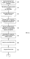
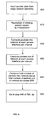
- This raw data is processed through a preparation procedure as set forth in steps 300 - 350 of FIGS. 3a and 3b in order to obtain the difference between the number of packets that went into the network and the number of packets that went out of the network during each collection interval, this is shown as Kc(i) in FIG. 2 .
- This signal Kc(i) can be used to detect data loss in the network, it is packets_in minus packets_out per interval. However, because of the lack of simultaneity in reading the raw data from the edge NEs, this signal fluctuates between positive and negative values.
- the mean of Kc(i) is zero in the case there is no loss in the network because eventually all input packets are accounted for at the output. When there is data loss in the network, the mean of the signal is positive since more packets go in than go out.
- the size of the upward shift in the mean of Kc(i) is a measure of data loss in the network. The fluctuations in Kc(i) represent noise in the data.
- FIG. 2 depicts a simplified version of the flow diagram of FIGS. 3a and 3b using multiple tap sizes N. Reference numerals in FIG. 2 refer to various steps described below with regard to FIGS. 3a and 3b .
- the filtered signal for each tap size is represented by y 1 , y 2 , ... y N in FIG. 2 . Under no data loss conditions, the signal y also has zero mean and shows an equivalent upward shift when there is data loss in the network.
- each signal y is integrated at step 370 to obtain the signals Iy 1 , Iy 2 ... Iy N .
- y shifts upward by a constant, and during the same period of time, Iy shows a linear growth upward.
- the procedure consists of applying a detectability criterion at step 410 based on the standard deviation of data computed (step 380, 420 or 440 ) prior to a predetermined window (either a default window set at steps 380 or 450 or chosen window size set at step 400 ) for a target threshold loss rate.
- a window is a period of time that covers a number of collection intervals during which the loss rate in the network is being measured. For a given FIR filter and from experience with previously obtained traffic data, it is known what size window is almost always large enough to meet a target threshold loss rate.
- a threshold loss rate is a value such that if the actual loss rate in the network exceeds it, we must be able to detect it. Typical thresholds are given as 10 -2 , 10 -3 , etc.
- the window is moved forward in time as new data becomes available.
- the detectability criterion is that the increase in Iy inside the window must be larger than approximately three times the computed standard deviation in the signal Iy. In this case we can measure the loss ratio in the network with approximately 97% confidence level.
- the data may be processed in parallel through low pass filters of different tap sizes as shown in FIG.2 .
- the reason for doing this is that there is a trade-off between delay and lower target threshold for loss rate.
- a filter of larger tap size will reduce noise by a larger factor and we will be able to detect a lower target loss ratio with it, however the larger tap size means we must wait longer to get a result. It is therefore useful to pass the data through filters of different tap sizes in order to observe the large loss ratios sooner. Small loss ratios require a longer time to detect in any case.
- FIGS. 3a and 3b show a functional block diagram of the loss ratio detection process.
- the counter data i.e., packet_count_in or byte_count_in and packet_count_out or byte_count_out
- the data is referred to as packet counter values or byte counter values in the network elements.
- packet counter values or byte counter values in the network elements.
- the next counter value shows how much the counter incremented over the intervals with missing data and the missing data can be filled in by linear interpolation at step 310.
- C(i), C(i+1),C(i+2),C(i+3) there should be an uninterrupted sequence (i.e., C(i), C(i+1),C(i+2),C(i+3),). If C(i+1), C(i+2),... C(i+N) are the values that are missing and C(i) and C(i+N+1) are the first and last known values on each side of the missing values then C ritht can be used as a placeholder value for C(i+N+1) and can be determined using the following sequence of equations (1).
- the difference calculation per collection interval is performed at step 320.
- Diff_Out(i+1) is the number of user packets going out of the egress NE from time i to time i+1.
- a 32-bit counter is being assumed in this example, although counter size could vary depending on the network element. Again, the addition of 2 32 compensates for counter overflow.
- the number of packets into the network minus packets out of the network for each interval is calculated as the difference between Diff_In(i+1) and Diff_Out(i+1), i.e., the difference between the number of packets that went into the network and the number of packets that went out of the network form time i to time i+1 as in equation (4).
- K ( i + 1 ) Diff_In ( i + 1 ) - Diff_Out ⁇ i + 1
- K(i) Because of the sampling time inaccuracy, even under no loss conditions K(i) will not be zero but will take on positive and negative values. However, under no loss conditions, every packet at the input eventually gets accounted at the output, so under no loss K(i) is a random variable with zero mean. A shift in the mean of K(i) toward a positive value indicates loss of data in the network. The random fluctuations in K(i) make it difficult or impossible to measure small data loss ratios because the upward shift in the mean is small compared to fluctuations in the signal, for the loss ratio sizes we are trying to measure.
- the loss ratio is defined as the amount of data lost divided by the data sent into the network by the user in a given period of time.
- step 330 must be invoked. This is the only step that is specific to byte counts. In some cases it may not be possible to get packet counts at both the ingress network element 110 and egress network element 120. Data packets at ingress and egress NEs may have different routing header size and the NEs report a byte count that includes user data and header. So even when there is no data loss in the network, the difference of bytes counted at the ingress and egress do not average to zero. This difference in header size can be accounted for because the number of bytes difference is a constant per packet. First the number of packets per interval must be computed per interval using the set of equations (5).
- Step 340 is performed whether byte data or packet data are being used and it consists of the removal of large variations in the data due to the occasional larger than usual sampling time, i.e., a lack of simultaneity at ingress and egress. Step 340 consists of the following algorithm.
- the standard deviation computed above is taken over a number of collection intervals (m-r+1) that would typically be about 10.
- K c (i) is larger than 10% of the average of the six nearby total input packet counts and also larger than three times the average of the five nearby K c (i) values, it will be assumed that it is due to counter update failure. K c (i) will be replaced in this case by the average of the other five nearby K c (i) values. If a change is made, the sign (positive or negative of K c (i) is maintained. This is accomplished at step 350 of FIG. 3a .
- C in (i) is the packet count at ingress NE 110 at sample time i.
- C in (i +1) packet count at ingress NE 110 at sample time i + 1.
- B(i + 1) total input packets between time i and (i -1).
- K(i) will be used to refer to the result of passing the data through steps 310 to 350.
- the basic principle of the method of the present invention for detecting small loss ratios is to use digital signal processing techniques to reduce the noise in the signal (i.e., the fluctuation in the K(i)).
- K(i) can be considered as a digital signal.
- fluctuations in K(i) have a period of variation of the order of one, i.e, K is changing significantly from one sample to the next. This is the high frequency component of the fluctuations and most of the fluctuation is at the high frequency side of the spectrum of the signal.
- the application of a low pass digital filter to K(i) will greatly reduce the high frequency noise allowing us to more easily detect an upward shift in the mean, the mean of the filtered signal will shift by the same amount as the unfiltered signal.
- a FIR filter of length L is applied as the low pass filter.
- K(n) is the input sample
- h(m) are the weights of the FIR filter.
- equation 12 becomes equation (13) below.
- y ( n ) ( 1 / 6 ) * K ( n ) + K ( n - 1 ) + K ( n - 2 ) + K ( n - 3 ) + K ( n - 4 ) + K ⁇ n - 5
- L depends on the tradeoff between degree of smoothing and processing delay. The larger L is, the greater the reduction in the noise but the longer it will take to get a result because more K(i) samples are needed.
- Another example of a low pass filter is the concatenation of two moving average FIR filters. That is applying one averaging filter and then again another averaging filter to the result of applying the first filter.
- the data may be processed in parallel (simultaneously) through more than one low pass filter. As depicted in FIG. 2 a plurality of N different tap sizes could be used. Steps 370 through 460 would be performed for each of these parallel processes.
- a filter with larger tap size involves a longer processing delay but can detect smaller loss ratios. The reason for using filters of different tap sizes is to be able to detect the larger loss ratios sooner.
- the integration of the filtered data occurs.
- FIG. 4 shows a plot of the integrated signal I(j) 420 for a sample of data collected from routers. Superimposed on the signal is some data loss 410 that causes the signal to ramp upward. It is the upward displacement of I(j) that we are trying to measure. It must be discriminated from the noise in the signal as seen in the fluctuations of I(j) 420 in FIG. 4 .
- a default window size is selected from experience with data from NEs.
- the default widow size depends on the low pass filter being used, on the degree of simultaneity of the measurements at the NEs, and on the characteristics of the traffic.
- the default window size is chosen so that the detectability test in step 410 is usually satisfied and it is not necessary to use a larger window in order to meet a target loss rate.
- An iteration counter, n is used to count the number of times the algorithm loop described below has been executed. After each iteration the left edge of the detection window is shifted one collection interval to the right (ahead in time).
- set ⁇ ⁇ . Note that this ⁇ is used only for default initialization of ⁇ .
- the subsequent updates of ⁇ are done at step 420. Note that the standard deviation is not calculated in the window in which the loss ratio is measured but rather is calculated using a number of data points to the left of (i.e., prior in time to) the window.
- the iteration counter is incremented.
- the smallest window that meets the target loss rate is chosen.
- T 10 -2 , 10 -3 , etc.
- the number of packets lost in the window would be TwM, where wM is the total number of packets that went into the network during the window and M is the average number of packets into the network per collection interval in the window.
- TwM the number of packets lost in the window
- M is the average number of packets into the network per collection interval in the window.
- the window size must be the smallest that satisfies the target rate condition, a larger window would clearly satisfy the inequality but would lead to greater delay in obtaining a loss rate measurement.
- the period over which the standard deviation is to be computed must be large enough to be representative of the I(j) signal but not too long to delay the measurement process.
- the previous 10 or 15 values of I(j) may be used.
- the sample of I(j) over which ⁇ is computed must be a continuous stretch over which no loss was detectable. Data loss shifts I(j) upward and would skew the value of ⁇ . This is why the previous ⁇ is used at step 440.
- a detectability test is applied inside the window to determine if the loss is properly measurable inside the selected window.
- the total number of packets into the network minus the total number of packets out is set forth in equation (17).
- Step 450 is arrived at from either step 420 or 440.
- the left edge of the window is moved one time interval to the right, i.e., replace a by a+1.
- the default window size, as discussed in block 380 is selected. If one more data point is not yet available, the process waits until it becomes available from the preprocessing steps 410 to 480 and the procedure is repeated by returning to step 390 where the iteration counter is incremented.
- a virtual private network 500 there are a plurality of customer premises equipment (CPE) 510 as shown in FIG. 5 .
- the CPE 510 are connected by a link 515 to an interface on the edge network elements 520 (which can be NEs other than routers). It is desired to measure the data loss rate in the network that originated from the VPN. It is assumed that at each edge network element the amount of data going into the network and the amount of data leaving the network can be measured. In a VPN, traffic from any site may be distributed to any of the other sites. It is assumed that only endpoint data is available.
- the loss ratio for the entire VPN can be determined using the same procedure used for the point to point case by aggregating the traffic into the network over all VPN edge links and aggregating the traffic out of the network over all VPN edge links. The process will apply only to non-multicast VPNs.
- This data is used at the input step 600 of FIG. 6 .
- the missing data is filled in by linear interpolation as step 310 of the flowchart of FIG. 3a .
- the packets into the VPN network at each access interface (j) 530 are determined in accordance with equations (20) and (21).
- C pin (j,i) is the input packet counter value at access interface j at sample time i.
- C pin (j,i+1) input packet counter value at access interface j at sample time i + 1.
- P in (j,i +1) number of packets into access interface j between time i and (i +1).
- a 32-bit counter is being assumed in this example.
- the packets out of the network at each access interface j are computed in accordance with equations (22) and (23).
- C pout (j,i) is the output packet counter value at access interface j at sample time i.
- C pout (j,i+1) is the output packet counter value at access interface j at sample time i + 1.
- P out (j,i +1) is the number of packets leaving access interface j between time i and (i +1).
- a 32-bit counter is being assumed in this example.
- step 640 the total number of packets for the VPN into the network minus the number of packets out of the network from time i to time i+1 is computed using formula (24).
- K p (i) is now used in the process depicted in flowchart of FIGS. 3a and 3b , in the same way as K(i), in order to measure data loss in a VPN.
- the K p (i) data is used by the process starting at step 340 of FIG. 3a in order to determine the loss ration in the VPN case.
- Step 330 is not necessary where packet counts rather than byte counts are used. It is not needed when it is known that the packet size in terms of the number of bytes is the same at the ingress and egress measurement points.
- Only one low pass filter may be used as a simplification of the method. This may increase the amount of time the process requires to properly measure detectable loss, but it reduces the overall complexity.
- Step 370 may be excluded as a simplification.
- the standard deviation is calculated using the K sequence instead of the I sequence. It has been found experimentally, that the standard deviation of the K sequence is about half of that of the I sequence. For this reason, the integration of step 370 is skipped, the detectability criterion in used in step 410 must be changed to D>6 ⁇ .
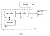
- FIG. 7 depicts a schematic diagram of a PLR measurement system 130 in accordance with the present invention.
- Processor 710 is a central processing unit such as that found in a personal computer, workstation, minicomputer or other general-purpose computer.
- Processor 710 is connected to memory 720 and input/output unit 730.
- Processor 710 is capable of executing computer program instructions compiled or translated from a variety of programming languages.
- Memory 720 stores the computer program capable of implementing the equations and algorithms described above in addition to packet count data or byte data received from ingress network element 110, egress network element 120 or, in the case of a VPN, the different edge network elements 510 at edge routers 520.
- Input/output unit 730 enables the processor 710 to receive packet or byte count data from one or more network elements such as an ingress network element 110 and to display to a user the calculated packet loss ration on display 740.
- Counter data may be obtained from the network elements in various ways, which are well established in the network services industry.
- the networks elements are connected by an internal internetwork or equivalent internal communications system.
- the network elements sample the data at the predetermined times and send their data files to a central location.
- the networks elements are connected by an internal internetwork or equivalent internal communications system.
- a central computer sends requests (by SNMP for example) to the network elements for them to respond with the data.
- Large network services providers already have operations support systems that can collect the data needed for this method of determining loss rate.
Landscapes
- Engineering & Computer Science (AREA)
- Computer Security & Cryptography (AREA)
- Computer Networks & Wireless Communication (AREA)
- Signal Processing (AREA)
- Data Exchanges In Wide-Area Networks (AREA)
- Maintenance And Management Of Digital Transmission (AREA)
- Detection And Prevention Of Errors In Transmission (AREA)
Claims (29)
- Verfahren zum Messen einer Datenverlustrate in einem Netzwerk mit einem Eingangsnetzwerkelement und einem Ausgangsnetzwerkelement, das die Schritte aufweist:Eingeben von Zählerdaten, die die Datenanzahl in das Netzwerk hinein an dem Eingangsnetzwerkelement messen;Eingeben von Zählerdaten, die die Datenanzahl aus dem Netzwerk heraus an dem Ausgangsnetzwerkelement messen; Berechnen der Differenz zwischen der Datenanzahl in das Netzwerk hinein und der Datenanzahl aus dem Netzwerk heraus für jedes einer Vielzahl von vorgegebenen Intervallen, um ein Datendifferenzsignal zu erzeugen;Anwenden eines Tiefpassfilters auf das Datendifferenzsignal, um ein gefiltertes Datendifferenzsignal zu erzeugen;Berechnen der Standardabweichung des gefilterten Datendifferenzsignals unter Verwendung von Daten unmittelbar vor einem vorgegebenen Fenster;Berechnen der Datenverlustrate basierend auf dem gefilterten Datendifferenzsignal in dem vorgegebenen Fenster; undBerichten der Datenverlustrate, wenn die Datenverlustrate eine vorgegebene Erfassbarkeitsschwelle überschreitet, basierend auf der berechneten Standardabweichung des gefilterten Datendifferenzsignals.
- Verfahren gemäß Anspruch 1, das weiter aufweist den Schritt eines Integrierens des gefilterten Datensignals vor einem Berechnen der Standardabweichung des gefilterten Signals.
- Verfahren gemäß Anspruch 1, das weiter aufweist die erneute Erzeugung einer "fehlende Daten"-Anzahl durch eine Interpolation vor einer Berechnung der Differenz zwischen der Datenanzahl in das Netzwerk hinein und der Datenanzahl aus dem Netzwerk heraus.
- Verfahren gemäß Anspruch 1, das weiter aufweist, vor einem Anwenden des Filters, den Schritt eines Korrigierens der Datenanzahl aufgrund von Routing-Header-Größenunterschieden an dem Eingangsnetzwerkelement und dem Ausgangsnetzwerkelement aufgrund der Verwendung von Byte-Zähl-Daten.
- Verfahren gemäß Anspruch 1, das weiter aufweist, vor einem Anwenden des Filters, den Schritt eines Entfernens von Variationen in der Datenanzahl aufgrund von länger als normalen Abtastzeiten an den Eingangs- oder Ausgangsnetzwerkelementen.
- Verfahren gemäß Anspruch 1, das weiter aufweist, vor einem Anwenden des Filters, den Schritt eines Anpassens der Datenanzahl, wenn das Netzwerkelement seine internen Zähler nicht richtig aktualisiert.
- Verfahren gemäß Anspruch 1, wobei die vorgegebene Erfassbarkeitsschwelle ungefähr sechs Mal die berechnete Standardabweichung des gefilterten Differenzdatensignals ist.
- Verfahren gemäß Anspruch 2, wobei die vorgegebene Erfassbarkeitsschwelle ungefähr drei Mal die berechnete Standardabweichung des gefilterten und integrierten Differenzdatensignals ist.
- Verfahren gemäß Anspruch 1, das weiter die Schritte aufweist:Berichten, dass der Datenverlust geringer ist als die vorgegebene Erfassbarkeitsschwelle;Berechnen einer neuen berechneten Standardabweichung für das gefilterte Differenzdatensignal basierend auf dem gleitenden Mittelwert der letzten zwei berechneten Standardabweichungen; Verschieben des vorgegebenen Fensters um ein Intervall in der Zeit nach vorne; undWiederholen der obigen Schritte, bis die vorgegebene Erfassbarkeitsschwelle überschritten wird.
- Verfahren gemäß Anspruch 1, das weiter aufweist ein Anwenden einer zusätzlichen Vielzahl von Tiefpassfiltern mit unterschiedlichen Tap-Größen und paralleles Durchführen jedes der nachfolgenden Schritte auf den jeweiligen gefilterten Differenzsignalen.
- Verfahren gemäß Anspruch 1, wobei die Größe des vorgegebenen Fensters basiert auf der gewünschten Zielverlustrate und der berechneten Standardabweichung des gefilterten Datendifferenzsignals.
- Verfahren zum Messen eines Datenverlusts in einem "Virtual Private Network" mit einer Vielzahl von Randnetzwerkelementen, das die Schritte aufweist:Eingeben von Zählerdaten von jedem Randnetzwerkelement; Berechnen der Menge von Daten in das Netzwerk hinein an jedem Randnetzwerkelement und der Menge von Daten aus dem Netzwerk heraus an jedem Randnetzwerkelement aus den Zählerdaten für eine Vielzahl von vorgegebenen Intervallen; Berechnen der Differenz zwischen der gesamten Menge von Daten in das Netzwerk hinein und der gesamten Menge einer Datenanzahl aus dem Netzwerk heraus für jedes der vorgegebenen Intervalle, um ein Datendifferenzsignal zu erzeugen;Anwenden eines Tiefpassfilters auf das Datendifferenzsignal, um ein gefiltertes Datendifferenzsignal zu erzeugen;Berechnen der Standardabweichung des gefilterten Datendifferenzsignals unter Verwendung von Daten unmittelbar vor einem vorgegebenen Fenster;Berechnen der Datenverlustrate basierend auf dem gefilterten Datendifferenzsignal in dem vorgegebenen Fenster; undBerichten der Datenverlustrate, wenn die Datenverlustrate eine vorgegebene Erfassbarkeitsschwelle überschreitet, basierend auf der berechneten Standardabweichung des gefilterten Datendifferenzsignals.
- Verfahren gemäß Anspruch 12, das weiter aufweist den Schritt eines Integrierens des gefilterten Datensignals vor einem Berechnen der berechneten Standardabweichung des gefilterten Signals.
- Verfahren gemäß Anspruch 12, das weiter aufweist die erneute Erzeugung einer "fehlende Daten"-Anzahl durch eine Interpolation vor einer Berechnung der Differenz zwischen der gesamten Menge von Daten in das Netzwerk hinein und der gesamten Menge von Daten aus dem Netzwerk heraus.
- Verfahren gemäß Anspruch 12, das weiter aufweist, vor einem Anwenden des Filters, den Schritt eines Entfernens von Variationen in der Datenanzahl aufgrund von länger als normalen Abtastzeiten an einem oder mehreren Randnetzwerkelementen.
- Verfahren gemäß Anspruch 12, das weiter aufweist, vor einem Anwenden des Filters, den Schritt eines Anpassens der Datenanzahl, wenn ein oder mehrere Randnetzwerkelement(e) einen internen Zähler nicht richtig aktualisiert hat/haben.
- Verfahren gemäß Anspruch 12, wobei die vorgegebene Erfassbarkeitsschwelle ungefähr sechs Mal die berechnete Standardabweichung des gefilterten Datendifferenzsignals ist.
- Verfahren gemäß Anspruch 13, wobei die vorgegebene Erfassbarkeitsschwelle ungefähr drei Mal die berechnete Standardabweichung des gefilterten und integrierten Differenzdatensignals ist.
- Verfahren gemäß Anspruch 12, das weiter die Schritte aufweist:Berichten, dass der Datenverlust geringer ist als die vorgegebene Erfassbarkeitsschwelle;Berechnen einer neuen berechneten Standardabweichung für das gefilterte Datendifferenzsignal basierend auf einem Mittelwert der letzten zwei berechneten Standardabweichungen; Verschieben des vorgegebenen Fensters um ein Intervall in der Zeit nach vorne; undWiederholen der obigen Schritte, bis die vorgegebene Erfassbarkeitsschwelle überschritten wird.
- Verfahren gemäß Anspruch 12, das weiter aufweist ein Anwenden einer zusätzlichen Vielzahl von Tiefpassfiltern mit unterschiedlichen Tap-Größen und paralleles Durchführen jedes der nachfolgenden Schritte auf den jeweiligen gefilterten Differenzsignalen.
- System zum Messen der Datenverlustrate in einem Netzwerk mit einem Eingangsnetzwerkelement und einem Ausgangsnetzwerkelement, das aufweist:Mittel zum Eingeben von Zählerdaten, die die Datenanzahl in das Netzwerk hinein an dem Eingangsnetzwerkelement und die Datenanzahl aus dem Netzwerk heraus an dem Ausgangsnetzwerkelement messen;Mittel zum Berechnen der Differenz zwischen der Datenanzahl in das Netzwerk hinein und der Datenanzahl aus dem Netzwerk heraus für jedes einer Vielzahl von vorgegebenen Intervallen, um ein Datendifferenzsignal zu erzeugen;Mittel zum Anwenden eines Tiefpassfilters auf das Datendifferenzsignal, um ein gefiltertes Datendifferenzsignal zu erzeugen; Mittel zum Berechnen der Standardabweichung des gefilterten Datendifferenzsignals über einen Satz von Datenpunkten unmittelbar vor einem vorgegebenen Fenster;Mittel zum Berechnen der Datenverlustrate basierend auf dem Datendifferenzsignal in dem vorgegebenen Fenster; undMittel zum Berichten der Datenverlustrate, wenn der Datenverlust eine vorgegebene Erfassbarkeitsschwelle überschreitet, basierend auf der berechneten Standardabweichung des gefilterten Differenzsignals.
- System gemäß Anspruch 21, das weiter aufweist Mittel zum Integrieren des gefilterten Datensignals vor einem Berechnen der Standardabweichung des Datendifferenzsignals.
- System gemäß Anspruch 21, das weiter aufweist Mittel für die erneute Erzeugung einer "fehlende Daten"-Anzahl durch eine Interpolation vor einer Berechnung der Differenz zwischen der Datenanzahl in das Netzwerk hinein und der Datenanzahl aus dem Netzwerk heraus.
- System gemäß Anspruch 21, das weiter aufweist, Mittel zum Korrigieren der Datenanzahl aufgrund von Routing-Header-Größenunterschieden an dem Eingangsnetzwerkelement und dem Ausgangsnetzwerkelement aufgrund der Verwendung von Byte-Zähl-Daten.
- System gemäß Anspruch 21, das weiter aufweist Mittel zum Entfernen von Variationen in der Datenanzahl aufgrund von länger als normalen Abtastzeiten an den Eingangs- oder Ausgangsnetzwerkelementen.
- System gemäß Anspruch 21, das weiter aufweist Mittel zum Anpassen der Datenanzahl, wenn das Netzwerkelement seine internen Zähler nicht richtig aktualisiert.
- System gemäß Anspruch 21, wobei die vorgegebene Erfassbarkeitsschwelle ungefähr sechs Mal die berechnete Standardabweichung des gefilterten Datendifferenzsignals ist.
- System gemäß Anspruch 22, wobei die vorgegebene Erfassbarkeitsschwelle ungefähr drei Mal die berechnete Standardabweichung des gefilterten und integrierten Datendifferenzsignals ist.
- System gemäß Anspruch 21, das weiter aufweist:Mittel zum Berichten, dass der Datenverlust geringer ist als die vorgegebene Schwelle;Mittel zum Berechnen einer neuen Standardabweichung für das gefilterte Datendifferenzsignal basierend auf dem gleitenden Mittelwert der letzten zwei berechneten Standardabweichungen; undMittel zum Verschieben des vorgegebenen Fensters um ein Intervall in der Zeit nach vorne.
Applications Claiming Priority (3)
| Application Number | Priority Date | Filing Date | Title |
|---|---|---|---|
| US356089 | 2003-01-31 | ||
| US10/356,089 US6839328B2 (en) | 2003-01-31 | 2003-01-31 | Measurement of packet loss ratio in a network using end-point data |
| PCT/US2004/002343 WO2004070537A2 (en) | 2003-01-31 | 2004-01-28 | Measurement of packet loss ratio in a network using end-point data |
Publications (3)
| Publication Number | Publication Date |
|---|---|
| EP1593017A2 EP1593017A2 (de) | 2005-11-09 |
| EP1593017A4 EP1593017A4 (de) | 2008-04-23 |
| EP1593017B1 true EP1593017B1 (de) | 2008-12-10 |
Family
ID=32770711
Family Applications (1)
| Application Number | Title | Priority Date | Filing Date |
|---|---|---|---|
| EP04706027A Expired - Lifetime EP1593017B1 (de) | 2003-01-31 | 2004-01-28 | Messung des packetverlustverhältnisses in einem netzwerk unter verwendung von endpunktdaten |
Country Status (6)
| Country | Link |
|---|---|
| US (1) | US6839328B2 (de) |
| EP (1) | EP1593017B1 (de) |
| JP (1) | JP4189000B2 (de) |
| CA (1) | CA2512459C (de) |
| DE (1) | DE602004018271D1 (de) |
| WO (1) | WO2004070537A2 (de) |
Families Citing this family (16)
| Publication number | Priority date | Publication date | Assignee | Title |
|---|---|---|---|---|
| US7177271B2 (en) * | 2001-09-21 | 2007-02-13 | Microsoft Corporation | Method and system for managing admission to a network |
| JP3896879B2 (ja) * | 2002-03-22 | 2007-03-22 | 日本電気株式会社 | トラヒック監視システム |
| AU2003260381A1 (en) * | 2003-08-07 | 2005-02-25 | Telecom Italia S.P.A. | A method for the statistical estimation of the traffic dispersion in telecommunication network |
| DE102004016581A1 (de) * | 2004-03-31 | 2005-10-27 | Nec Europe Ltd. | Verfahren zur Durchführung von Abrechnungs- und Vergütungsprozessen in Ad Hoc Netzwerken |
| JP4447604B2 (ja) * | 2004-09-03 | 2010-04-07 | アンリツ株式会社 | 欠落パケット測定装置およびそれを用いた誤り率測定装置 |
| KR20070109134A (ko) * | 2006-05-09 | 2007-11-15 | 엘지전자 주식회사 | 프리즘 시트, 이를 구비한 백라이트 유닛 및 액정표시장치 |
| US7646731B2 (en) * | 2006-12-19 | 2010-01-12 | Cisco Technology, Inc. | Route monitoring in a network management system |
| US8345573B2 (en) | 2007-11-26 | 2013-01-01 | Nec Corporation | Communication quality estimation system, equipment, method and program |
| GB2460070B (en) * | 2008-05-15 | 2010-10-13 | Gnodal Ltd | A method of data delivery across a network |
| KR20110123651A (ko) * | 2010-05-07 | 2011-11-15 | 한국전자통신연구원 | 생략 부호화를 이용한 영상 부호화 및 복호화 장치 및 그 방법 |
| WO2013092634A1 (en) | 2011-12-20 | 2013-06-27 | Thomson Licensing | Methods for monitoring data traffic in a gateway device |
| CN103152226B (zh) * | 2013-03-26 | 2016-08-24 | 杭州晨晓科技有限公司 | 一种mpls-tp网络保护的丢包率测量方法 |
| US10225161B2 (en) * | 2016-10-31 | 2019-03-05 | Accedian Networks Inc. | Precise statistics computation for communication networks |
| US12041303B1 (en) * | 2018-03-19 | 2024-07-16 | Amazon Technologies, Inc. | Bandwidth estimation for video encoding |
| US11171890B1 (en) * | 2018-12-28 | 2021-11-09 | Innovium, Inc. | Reducing power consumption in an electronic device |
| US11907676B1 (en) * | 2020-08-28 | 2024-02-20 | Amazon Technologies, Inc. | Processing orchestration for systems including distributed components |
Family Cites Families (7)
| Publication number | Priority date | Publication date | Assignee | Title |
|---|---|---|---|---|
| US6188674B1 (en) * | 1998-02-17 | 2001-02-13 | Xiaoqiang Chen | Method and apparatus for packet loss measurement in packet networks |
| US6580721B1 (en) * | 1998-08-11 | 2003-06-17 | Nortel Networks Limited | Routing and rate control in a universal transfer mode network |
| US6594268B1 (en) * | 1999-03-11 | 2003-07-15 | Lucent Technologies Inc. | Adaptive routing system and method for QOS packet networks |
| US7423983B1 (en) * | 1999-09-20 | 2008-09-09 | Broadcom Corporation | Voice and data exchange over a packet based network |
| CA2291835A1 (en) * | 1999-12-06 | 2001-06-06 | Nortel Networks Corporation | Load adaptive buffer management in packet networks |
| JP4328459B2 (ja) * | 2000-10-27 | 2009-09-09 | Necエンジニアリング株式会社 | ネットワークのサービス品質測定システム及びその方法 |
| US6914883B2 (en) * | 2000-12-28 | 2005-07-05 | Alcatel | QoS monitoring system and method for a high-speed DiffServ-capable network element |
-
2003
- 2003-01-31 US US10/356,089 patent/US6839328B2/en not_active Expired - Fee Related
-
2004
- 2004-01-28 CA CA002512459A patent/CA2512459C/en not_active Expired - Fee Related
- 2004-01-28 EP EP04706027A patent/EP1593017B1/de not_active Expired - Lifetime
- 2004-01-28 WO PCT/US2004/002343 patent/WO2004070537A2/en not_active Ceased
- 2004-01-28 DE DE602004018271T patent/DE602004018271D1/de not_active Expired - Lifetime
- 2004-01-28 JP JP2006501125A patent/JP4189000B2/ja not_active Expired - Fee Related
Also Published As
| Publication number | Publication date |
|---|---|
| WO2004070537A2 (en) | 2004-08-19 |
| EP1593017A4 (de) | 2008-04-23 |
| US6839328B2 (en) | 2005-01-04 |
| JP2006516855A (ja) | 2006-07-06 |
| EP1593017A2 (de) | 2005-11-09 |
| WO2004070537A3 (en) | 2004-09-30 |
| CA2512459A1 (en) | 2004-08-19 |
| DE602004018271D1 (de) | 2009-01-22 |
| US20040151123A1 (en) | 2004-08-05 |
| JP4189000B2 (ja) | 2008-12-03 |
| CA2512459C (en) | 2009-07-07 |
Similar Documents
| Publication | Publication Date | Title |
|---|---|---|
| EP1593017B1 (de) | Messung des packetverlustverhältnisses in einem netzwerk unter verwendung von endpunktdaten | |
| KR101443237B1 (ko) | 통신 네트워크에서의 데이터 흐름에 대한 측정 | |
| EP2374247B1 (de) | Steuerung von paketübertragung unter verwendung von bandbreitenschätzung | |
| US7808915B2 (en) | System for identifying and locating network problems | |
| KR101123020B1 (ko) | 고속 트래픽 측정 및 분석 방법론들 및 프로토콜들 | |
| KR20030058946A (ko) | 인터넷에서 보틀넥 대역폭의 강한 실시간 추정을 위한장치 및 방법 | |
| US6912575B1 (en) | System and method for automatically determining recommended committed information rate in a frame relay network | |
| EP2302845B1 (de) | Verfahren und Vorrichtung zur Bestimmung eines Jitterpuffer-Niveaus | |
| US9806976B2 (en) | Time measurement on a packet flow in a packet-switched communication network | |
| US8208395B2 (en) | System and method for measuring interface utilization using policers | |
| EP3369213B1 (de) | Leistungsmessung in einem paketvermittelten kommunikationsnetzwerk | |
| US7509229B1 (en) | Bayesian approach to correlating network traffic congestion to performance metrics | |
| EP3449602B1 (de) | Leistungsmessung auf ein mehrpunktpaketfluss | |
| EP3513529B1 (de) | Leistungsmessung in einem paketvermittelten kommunikationsnetzwerk | |
| US7443889B2 (en) | Network or service management system for determining the synchronization between two streams of packets | |
| US11165671B2 (en) | Performance measurement in a packet-switched communication network | |
| EP3891916B1 (de) | Leistungsmessung in einem paketvermittelten kommunikationsnetzwerk | |
| KR100902114B1 (ko) | 멀티미디어 스트리밍을 위한 종단간 가용 대역폭 측정 장치및 방법 | |
| US12470468B2 (en) | Processing of packets in a packet-switched communication network | |
| Aspirot et al. | End-to-end quality of service prediction based on functional regression |
Legal Events
| Date | Code | Title | Description |
|---|---|---|---|
| PUAI | Public reference made under article 153(3) epc to a published international application that has entered the european phase |
Free format text: ORIGINAL CODE: 0009012 |
|
| 17P | Request for examination filed |
Effective date: 20050822 |
|
| AK | Designated contracting states |
Kind code of ref document: A2 Designated state(s): AT BE BG CH CY CZ DE DK EE ES FI FR GB GR HU IE IT LI LU MC NL PT RO SE SI SK TR |
|
| AX | Request for extension of the european patent |
Extension state: AL LT LV MK |
|
| RIC1 | Information provided on ipc code assigned before grant |
Ipc: H04L 12/26 19900101AFI20051124BHEP |
|
| DAX | Request for extension of the european patent (deleted) | ||
| RBV | Designated contracting states (corrected) |
Designated state(s): DE FR GB IT SE |
|
| A4 | Supplementary search report drawn up and despatched |
Effective date: 20080320 |
|
| RIC1 | Information provided on ipc code assigned before grant |
Ipc: H04L 12/26 20060101AFI20051124BHEP Ipc: H04L 12/24 20060101ALI20080314BHEP |
|
| GRAP | Despatch of communication of intention to grant a patent |
Free format text: ORIGINAL CODE: EPIDOSNIGR1 |
|
| GRAS | Grant fee paid |
Free format text: ORIGINAL CODE: EPIDOSNIGR3 |
|
| GRAS | Grant fee paid |
Free format text: ORIGINAL CODE: EPIDOSNIGR3 |
|
| GRAA | (expected) grant |
Free format text: ORIGINAL CODE: 0009210 |
|
| AK | Designated contracting states |
Kind code of ref document: B1 Designated state(s): DE FR GB IT SE |
|
| REG | Reference to a national code |
Ref country code: GB Ref legal event code: FG4D |
|
| REF | Corresponds to: |
Ref document number: 602004018271 Country of ref document: DE Date of ref document: 20090122 Kind code of ref document: P |
|
| PG25 | Lapsed in a contracting state [announced via postgrant information from national office to epo] |
Ref country code: SE Free format text: LAPSE BECAUSE OF FAILURE TO SUBMIT A TRANSLATION OF THE DESCRIPTION OR TO PAY THE FEE WITHIN THE PRESCRIBED TIME-LIMIT Effective date: 20090310 |
|
| PLBE | No opposition filed within time limit |
Free format text: ORIGINAL CODE: 0009261 |
|
| STAA | Information on the status of an ep patent application or granted ep patent |
Free format text: STATUS: NO OPPOSITION FILED WITHIN TIME LIMIT |
|
| 26N | No opposition filed |
Effective date: 20090911 |
|
| PG25 | Lapsed in a contracting state [announced via postgrant information from national office to epo] |
Ref country code: IT Free format text: LAPSE BECAUSE OF FAILURE TO SUBMIT A TRANSLATION OF THE DESCRIPTION OR TO PAY THE FEE WITHIN THE PRESCRIBED TIME-LIMIT Effective date: 20081210 |
|
| REG | Reference to a national code |
Ref country code: GB Ref legal event code: 732E Free format text: REGISTERED BETWEEN 20111103 AND 20111109 |
|
| REG | Reference to a national code |
Ref country code: FR Ref legal event code: TP Owner name: MOSAID TECHNOLOGIES INCORPORATED, CA Effective date: 20111117 |
|
| REG | Reference to a national code |
Ref country code: DE Ref legal event code: R082 Ref document number: 602004018271 Country of ref document: DE Representative=s name: BEETZ & PARTNER PATENT- UND RECHTSANWAELTE, DE Effective date: 20120112 Ref country code: DE Ref legal event code: R081 Ref document number: 602004018271 Country of ref document: DE Owner name: CONVERSANT INTELLECTUAL PROPERTY MANAGEMENT IN, CA Free format text: FORMER OWNER: TELCORDIA TECHNOLOGIES, INC., PISCATAWAY, N.J., US Effective date: 20120112 Ref country code: DE Ref legal event code: R082 Ref document number: 602004018271 Country of ref document: DE Representative=s name: BEETZ & PARTNER MBB, DE Effective date: 20120112 Ref country code: DE Ref legal event code: R082 Ref document number: 602004018271 Country of ref document: DE Representative=s name: BEETZ & PARTNER MBB PATENTANWAELTE, DE Effective date: 20120112 Ref country code: DE Ref legal event code: R082 Ref document number: 602004018271 Country of ref document: DE Representative=s name: BEETZ & PARTNER MBB PATENT- UND RECHTSANWAELTE, DE Effective date: 20120112 |
|
| REG | Reference to a national code |
Ref country code: DE Ref legal event code: R082 Ref document number: 602004018271 Country of ref document: DE Representative=s name: BEETZ & PARTNER PATENT- UND RECHTSANWAELTE, DE |
|
| REG | Reference to a national code |
Ref country code: FR Ref legal event code: CA Effective date: 20141021 Ref country code: FR Ref legal event code: CD Owner name: CONVERSANT INTELLECTUAL PROPERTY MANAGEMENT IN, CA Effective date: 20141021 |
|
| REG | Reference to a national code |
Ref country code: DE Ref legal event code: R082 Ref document number: 602004018271 Country of ref document: DE Representative=s name: BEETZ & PARTNER PATENT- UND RECHTSANWAELTE, DE Effective date: 20141120 Ref country code: DE Ref legal event code: R081 Ref document number: 602004018271 Country of ref document: DE Owner name: CONVERSANT INTELLECTUAL PROPERTY MANAGEMENT IN, CA Free format text: FORMER OWNER: MOSAID TECHNOLOGIES INCORPORATED, OTTOWA, CA Effective date: 20141120 Ref country code: DE Ref legal event code: R082 Ref document number: 602004018271 Country of ref document: DE Representative=s name: BEETZ & PARTNER MBB, DE Effective date: 20141120 Ref country code: DE Ref legal event code: R082 Ref document number: 602004018271 Country of ref document: DE Representative=s name: BEETZ & PARTNER MBB PATENTANWAELTE, DE Effective date: 20141120 Ref country code: DE Ref legal event code: R082 Ref document number: 602004018271 Country of ref document: DE Representative=s name: BEETZ & PARTNER MBB PATENT- UND RECHTSANWAELTE, DE Effective date: 20141120 |
|
| REG | Reference to a national code |
Ref country code: FR Ref legal event code: PLFP Year of fee payment: 12 |
|
| PGFP | Annual fee paid to national office [announced via postgrant information from national office to epo] |
Ref country code: DE Payment date: 20150120 Year of fee payment: 12 |
|
| PGFP | Annual fee paid to national office [announced via postgrant information from national office to epo] |
Ref country code: GB Payment date: 20150128 Year of fee payment: 12 Ref country code: FR Payment date: 20150108 Year of fee payment: 12 |
|
| REG | Reference to a national code |
Ref country code: DE Ref legal event code: R119 Ref document number: 602004018271 Country of ref document: DE |
|
| GBPC | Gb: european patent ceased through non-payment of renewal fee |
Effective date: 20160128 |
|
| REG | Reference to a national code |
Ref country code: FR Ref legal event code: ST Effective date: 20160930 |
|
| PG25 | Lapsed in a contracting state [announced via postgrant information from national office to epo] |
Ref country code: GB Free format text: LAPSE BECAUSE OF NON-PAYMENT OF DUE FEES Effective date: 20160128 Ref country code: DE Free format text: LAPSE BECAUSE OF NON-PAYMENT OF DUE FEES Effective date: 20160802 |
|
| PG25 | Lapsed in a contracting state [announced via postgrant information from national office to epo] |
Ref country code: FR Free format text: LAPSE BECAUSE OF NON-PAYMENT OF DUE FEES Effective date: 20160201 |