EP1592863B1 - Verbessertes bohrlochwerkzeug - Google Patents
Verbessertes bohrlochwerkzeug Download PDFInfo
- Publication number
- EP1592863B1 EP1592863B1 EP04705112A EP04705112A EP1592863B1 EP 1592863 B1 EP1592863 B1 EP 1592863B1 EP 04705112 A EP04705112 A EP 04705112A EP 04705112 A EP04705112 A EP 04705112A EP 1592863 B1 EP1592863 B1 EP 1592863B1
- Authority
- EP
- European Patent Office
- Prior art keywords
- piston
- groove
- downhole apparatus
- relative
- control
- Prior art date
- Legal status (The legal status is an assumption and is not a legal conclusion. Google has not performed a legal analysis and makes no representation as to the accuracy of the status listed.)
- Expired - Lifetime
Links
Images


Classifications
-
- E—FIXED CONSTRUCTIONS
- E21—EARTH OR ROCK DRILLING; MINING
- E21B—EARTH OR ROCK DRILLING; OBTAINING OIL, GAS, WATER, SOLUBLE OR MELTABLE MATERIALS OR A SLURRY OF MINERALS FROM WELLS
- E21B23/00—Apparatus for displacing, setting, locking, releasing or removing tools, packers or the like in boreholes or wells
- E21B23/004—Indexing systems for guiding relative movement between telescoping parts of downhole tools
- E21B23/006—"J-slot" systems, i.e. lug and slot indexing mechanisms
-
- E—FIXED CONSTRUCTIONS
- E21—EARTH OR ROCK DRILLING; MINING
- E21B—EARTH OR ROCK DRILLING; OBTAINING OIL, GAS, WATER, SOLUBLE OR MELTABLE MATERIALS OR A SLURRY OF MINERALS FROM WELLS
- E21B21/00—Methods or apparatus for flushing boreholes, e.g. by use of exhaust air from motor
- E21B21/10—Valve arrangements in drilling-fluid circulation systems
- E21B21/103—Down-hole by-pass valve arrangements, i.e. between the inside of the drill string and the annulus
-
- E—FIXED CONSTRUCTIONS
- E21—EARTH OR ROCK DRILLING; MINING
- E21B—EARTH OR ROCK DRILLING; OBTAINING OIL, GAS, WATER, SOLUBLE OR MELTABLE MATERIALS OR A SLURRY OF MINERALS FROM WELLS
- E21B23/00—Apparatus for displacing, setting, locking, releasing or removing tools, packers or the like in boreholes or wells
- E21B23/004—Indexing systems for guiding relative movement between telescoping parts of downhole tools
-
- E—FIXED CONSTRUCTIONS
- E21—EARTH OR ROCK DRILLING; MINING
- E21B—EARTH OR ROCK DRILLING; OBTAINING OIL, GAS, WATER, SOLUBLE OR MELTABLE MATERIALS OR A SLURRY OF MINERALS FROM WELLS
- E21B34/00—Valve arrangements for boreholes or wells
- E21B34/06—Valve arrangements for boreholes or wells in wells
- E21B34/10—Valve arrangements for boreholes or wells in wells operated by control fluid supplied from outside the borehole
Definitions
- the invention relates to apparatus for use in well bores and particularly, but not exclusively, to circulating subs used during downhole drilling operations.
- a cylindrical piston is generally provided for axial movement within a sub housing between an open position, in which well bore fluid may flow between the annulus and the interior of the sub housing by means of apertures in said housing, and a closed configuration, in which the piston covers the apertures so as to prevent a flow ofwell bore fluid therethrough.
- the piston is biased uphole by means of a spring and, in use, is pressed downhole by a predetermined rate of fluid flow through the sub housing.
- movement of the piston is controlled by means of a pin and groove arrangement.
- a control groove is typically provided in the outer surface of the piston as a closed loop about the longitudinal axis of the piston.
- At least one control pin is secured to the sub housing so as to extend into the control groove. Movement of the piston relative to the sub housing is therefore limited by movement of the control pin within the control groove.
- the control groove is shaped so that, on at least one application of the predetermined fluid flow rate downhole through the sub housing, the piston is allowed to move axially but prevented from changing the open or closed configuration of the circulating sub. In moving axially, the piston rotates within the sub housing as the control pin moves circumferentially within the control groove.
- the piston may be pressed uphole by the biasing means and be further rotated by a further relative movement between the control pin and groove.
- the piston has been cycled between uphole and downhole positions, it will be appreciated that, with an appropriate positioning of housing apertures relative to the piston, no change in the open or closed configuration of the circulating sub need occur.
- the control groove may be shaped so that, after a predetermined number of piston cycles, the pin is located in a portion of control groove which extends a sufficient axial distance to permit the piston to be moved downhole by said predetermined flow rate and thereby change the open/closed configuration.
- the open/closed configuration of the circulating sub will be changed only after a predetermined number of applications of the aforementioned fluid flow rate. The use of fluid flow rate above the level required to move the piston is not therefore prevented by use of the circulating sub.
- control pin and groove arrangements of the above prior art circulating sub causes the piston to rotate with a helical motion.
- the piston moves with both axial and rotational components.
- the rotational movement can be undesirable in that the piston can stick during the spring return cycle with the control pin being driven back along the portion of control groove from which it has just moved.
- a circulating sub having an open configuration wherein fluid flows through the housing apertures to the annulus via flow ports in the wall of the cylindrical piston, care must be taken during the design, manufacture and assembly of the sub to ensure that the piston ports align with the housing apertures when the piston is in the open axial position or to ensure that means, such as a circumferential housing recess in the region of the apertures, is provided in order to allow fluid communication between misaligned piston ports and housing apertures.
- a bypass valve is shown in US-A- 6,289,999 in which the piston rotatable relative to both the apparatus body and a sleeve (located between the piston and body) in which a control groove is defined.
- a problem with this arrangement is that rotational movement of the piston (arising from a swirling fluid flow in the piston bore or some other event) independent of the relative movement between the control groove and associated control pin can cause the pin to undesirably move backwards within the control groove and prevent the apparatus from moving between open and closed configurations as expected.
- a downhole apparatus is shown in US-A-4718494 which comprises a mandrel that acts as a piston shiftable by the differential of fluid pressure between the interior of the tool and a well annulus.
- Axial movement of the piston is controlled by a relatively complex arrangement comprising a groove formed in the piston, a pin which works in the groove and is secured to a lower sleeve, a first one-way clutch located between the lower sleeve and an upper sleeve, a second one-way clutch located between the upper sleeve and the body, a groove provided in the upper sleeve and lugs provided on the mandrel.
- the control groove in the piston comprises two axially extending portions which are offset from each other in the circumferential direction and are connected by an obliquely extending groove.
- the first is that the arrangement is complex and requires a large number of components including two one-way clutches.
- the complexity of this arrangement adds to the cost of the tool and potentially adversely affects reliability of the tool.
- a further disadvantage is that the actual forward rotation of the upper sleeve which is produced by any particular axial movement of the mandrel is to an extent determined by the amount of axial movement involved.
- the rotational movement of the upper sleeve is not quantized but could, for example, be a very small movement if the mandrel is reciprocated through a small vertical distance.
- a bypass valve differs from a circulating sub (to which the present invention particularly relates) in that a bypass valve is normally located in an open configuration so as to allow fluid communication between the annulus and the valve interior.
- a mutli-cycle bypass valve will generally cycle several times whilst remaining open before moving to a closed configuration.
- a multi-cycle circulating sub will, in contrast, generally cycle several times whilst remaining in a closed configuration before opening to allow fluid communication with the annulus.
- the problems of the prior art, and in particular those associated with US-A-4718494 are avoided and a relatively simple and robust arrangement is provided for effecting the required controlled movement of the piston.
- the use of a circumferentially continuous groove with an extension such that when the pin moves into the extension the piston may adopt an extended travel position leads to a particular simple and robust arrangement and obviates the need for the clutches and upper sleeve of US-A-4718494 .
- the present invention provides a method whereby the axial movement control arrangement of GB-A-2377234 may be applied to a circulating sub in which there is no rotation of the piston relative to the body.
- the piston is prevented from moving in a rotational direction relative to the body by constraining means.
- rotational forces applied to the piston by, for example, a swirling fluid flow or apparatus located within the piston bore, are prevented from being transferred to the control groove or control pin and, accordingly, the risk of the control pin undesirably moving backwards within the control groove is reduced.
- said means for constraining relative movement between the piston and the body comprises a straight groove extending in a longitudinal direction, said straight groove being provided on one of the piston and body, and a portion of the other of the piston and body being received within said groove.
- Said portion of the piston or body may be provided as a discrete pin separate from the piston or body.
- the constraining means may, in use, limit the extent of longitudinal movement of the piston relative to the body.
- the piston may be biased in a longitudinal direction by biasing means towards a plurality or positions relative to the body in which the downhole apparatus is in a closed position, and the control groove is adapted to allow movement from the closed configuration to the open configuration only after a predetermined number of longitudinal movements of the piston against the bias of the biasing means.
- Said means for preventing movement of the control member may comprise a groove extending in a plane perpendicular to the direction of longitudinal movement and a pin located in said groove; the groove being defined in one of the body and control member, and the pin being provided on the other of the body and control member.
- the piston may be releasably secured to the body by means of a collet when moved to a predetermined longitudinal position relative to the body. Only one portion of the control groove may permit movement of the piston to said predetermined longitudinal position relative to the body so as to allow the piston to become secured to the body by means of the collet.
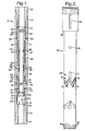
- a first multi-cycle circulating sub 2 according to the present invention is shown in Figures 1-4 of the accompanying drawings.
- the circulating sub 2 is moveable between a closed configuration, in which all wellbore fluid is directed through the interior of the sub, and an open configuration, in which all wellbore fluid is directed to the exterior of the sub.
- the sub 2 includes a housing in which a number of internal components are mounted.
- the housing is itself made up of several components.
- the housing components include a principal cylindrical body component 4, an internal cylindrical body component (a lower sleeve) 6, and uphole and downhole cylindrical crossover members 8,10.
- the crossover members 8,10 are threadedly connected to respective uphole and downhole ends 12, 14 of the principal body component 4.
- the uphole crossover member 8 has an internal screw thread at its uphole end (not shown) for screw-threaded engagement with a portion of equipment string to be located uphole of the sub 2.
- the downhole crossover member 10 is provided with an external screw thread at its downhole end (not shown) for screw threaded engagement with a portion of equipment string to be located downhole of the sub 2.
- the internal body component 6 locates within a bore 15 of the principal body component 4 in abutment with an uphole facing shoulder 16 defined by the downhole crossover member 10.
- a seal 18 is provided between the principal body component 4 and the internal body component 6 at the uphole and downhole ends of said internal body component 6.
- the internal body component 6 is fixedly secured to the principal body component 4 by means of two pins 20 extending from the principal body component 4 into recesses in the internal body component 6. Axial movement between the principal body component 4 and the internal body component 6 is thereby prevented.
- six vent apertures 22 extend transversely through the principal body component 4 and the internal body component 6 so as to allow, in use, well bore fluid to vent from the piston bore 28 to the exterior of the sub 2.
- the internal diameter of the internal body component 6 is increased downhole of the apertures 22 so that, in use, well bore fluid may flow from laterally extending ports in a piston (described in greater detail below) and into equipment located below the sub 2.
- the internal diameter of the internal body component is increased at the lower end of said component 6 so as to provide an uphole facing annular shoulder 24 for closing the aforementioned piston flow ports when the piston is located in the open position (see Figure 4).
- the piston referred to above is one of the internal components mounted in the housing of the circulating sub 2.
- An isolated view of the piston 26 is shown in Figure 2.
- the piston 26 has a generally cylindrical shape with an internal bore 28 extending therethrough.
- the downhole end of the piston bore 28 is sealed, although well bore fluid may flow from the bore 28 by means of twelve laterally extending flow ports 30.
- the flow ports 30 extend outwardly and downwardly from the piston bore 28 so as to direct fluid into the portion of the internal body component 6 having an increased internal diameter.
- An O-ring seal 32 is located radially inwardly of the outlets to the flow ports 30 on a downward facing downhole end surface 34 of the piston 26 (see Figure 1). When the piston 26 is located in the open position, the O-ring seal 32 abuts the upwardly facing shoulder 24 of the internal body component 6. Well bore fluid is thereby prevented from flowing into equipment located downhole of the sub 2.
- the downhole end of the piston 26 may be modified as shown in Figure 6 of the accompanying drawings.
- the downhole end of the piston 26 is provided with a downwardly projecting cylindrical extension 27 which is sized so as to be locatable within the aperture 25 defined in the lowermost portion of the internal body component 6.
- the arrangement is such that the extension 27 sealingly engages said aperture 25.
- This may be achieved by providing the extension 27 and the aperture 25 with a taper so that both the extension 27 and the aperture 25 reduce in diameter in a downhole axial direction. This tapering only needs to be relatively small and is not visible in the illustration of Figure 6.
- An O-ring seal 32' is provided (optionally) between the mating surfaces (preferably on the outer diameter surface of the extension 27).
- vent apertures 36 Uphole of the piston flow ports 30, the piston 26 is provided with six vent apertures 36 which are each located so as to align with a corresponding vent aperture 22 when the piston 26 is in the open position. With the piston vent apertures 36 so located, well bore fluid may flow from the piston bore 28 into the well bore annulus.
- a control groove 38 is defined in the outer surface of the piston 26 uphole of the vent apertures 36.
- the control groove 38 is of a conventional nature and circumscribes the piston 26 to form a closed loop.
- the control groove 3 8 is shaped so that a pin located therein will move circumferentially along the groove in response to reciprocating axial movement of the piston 26.
- the extent of axial piston movement is restricted by the interaction of the pin with the groove and is determined by the particular portion of groove in which the pin is located at any given time.
- Two spring chamber vent apertures 40 extend laterally through the wall of the piston 26 uphole of the control groove 38.
- the vent apertures 40 may be used to assist in preventing a hydraulic locking of the piston 26.
- a hydraulic locking of the piston 26 is prevented by means of two spring chamber vent apertures 42 defined in the principal body component 4 and the vent apertures 40 in the piston 26 are occluded with appropriate plugs.
- the outer diameter of the piston 26 increases at the piston upper end so as to define a downward facing annular shoulder 44.
- a helical spring 46 is located so as to press upwardly on the shoulder 44 and thereby bias the piston 26 in an uphole direction.
- two further grooves 48 are provided in the exterior surface of the piston 26 uphole of the shoulder 44.
- the two grooves 48 each extend in an axial direction only.
- two pins 50 secured to the principal body component 4 extend into the grooves 48.
- Each of the axially extending grooves 48 receive one pin 50. More or less than two grooves 48 may be provided as necessary. Since the grooves 48 extend in an axial direction only, it will be understood that, in the assembled circulating sub 2, the piston 26 is restrained by the pins 50 from rotating within the bore 15 and is capable only of moving in an axial direction.
- the length of the grooves 48 is such that the pins 50 do not limit the axial movement of the piston 26 (although the grooves 48 and pins 50 may be used for this purpose with appropriate modification of the groove 48 length and position).
- uphole movement of the piston 26 is limited by abutment of the piston 26 with the uphole crossover member 8 and downhole movement of the piston 26 is limited by abutment of the piston 26 with the shoulder 24.
- a chamber is defined between the piston 26, the principal body component 4 and the internal body component 6.
- This chamber houses the helical spring 46, two bearing raceways 60,62 (see below) and a cylindrical sleeve 52 to which two control pins 54 are secured (see Figures 3 and 4). Due to the rotational position of the pin sleeve 52, the pins 54 are not visible in Figure 1. With reference to Figures 3 and 4, it will be seen that the two control pins 54 extend from the inner surface of the pin sleeve 52 so as to locate within the control groove 3 8 defined in the piston 26.
- the restraining pins 56 and groove 58 function to prevent uphole movement of the pin sleeve 52 in particular. Downhole movement of the pin sleeve 52 is limited by the internal body component 6 as well as the restraining pins 56. It is to be noted that the restraining pins 56 are not visible in Figure 3 due to the angle at which the cross-section view has been taken.
- the rotational movement of the pin sleeve 52 is assisted by means of two bearings 60,62 and two slyd or wear rings 64,66.
- the first bearing 60 located between the downhole end of the pin sleeve 52 and the uphole end of the internal body component 6.
- the second bearing 62 is located between the uphole end of the pin sleeve 52 and the downhole end of the spring 46.
- the slyd or wear rings 64,66 are located adjacent the bearings 60,62 between the pin sleeve 52 and the principal body component 4.
- the axial movement of the piston 26 is assisted by means of a slyd or wear ring 68 located between the uphole end of the piston 26 and the principal body component 4 and a slyd or wear ring seal 70 located between the piston 26 and the internal body component 6. In this way, frictional forces resisting axial movement of the piston 26 relative to the housing are reduced. Also, glyd ring seals 72,74,76,78 prevent the passage of well bore fluid between the piston 26 and the sub housing.
- a nozzle 80 may be located within the piston bore 28 so as to increase pressure losses and allow a greater force to be exerted on the piston 26 by a given fluid flow.
- the size of the nozzle 80 may of course be varied so as to vary the fluid flow required to generate a force necessary to overcome the spring bias.
- the piston 26 may be located in a closed position as shown in Figure 1 so that fluid may be pumped through the circulating sub to equipment located downhole thereof.
- each of the control pins 54 is located in one of the lowermost portions A of the control groove 3 8 (see Figure 2).
- fluid may flow through the piston bore 28 and into equipment located downhole via the piston flow ports 30. If the fluid rate increases to such an extent that the bias of the spring 46 is overcome, then the piston 26 will be pressed downhole by the fluid flow.
- the piston 26 In moving downhole, the piston 26 is restrained by the grooves 48 and pins 50 from rotating relative to the housing. However, as the piston 26 moves axially relative to the housing, the pin sleeve 52 rotates and the control pins 54 move to a different portion of the control groove 38.
- control pins 54 are initially located within the control groove 3 8 so as to each move to a portion B of the control groove 3 8 upon axial movement of the piston 26, then movement of the piston 26 to the open position (as shown in Figure 4) will be prevented. Thus, fluid may still be pumped to fluid located below the sub 2. If the fluid flow rate is reduced sufficiently, the spring 46 will move the piston 26 back uphole into abutment with the uphole cross-over member 8. In moving uphole, the piston 26 does not rotate due to the constraining influence of the grooves 48 and pins 50. However, the pin sleeve 52 does rotate and each control pin 54 moves to a new portion A of the control groove 38.
- the profile of the control groove 38 is such that movement of each control pin 54 from some (but not all) lowermost portions A of the control groove 38, as the piston 26 moves downhole, allows each control pin 54 to locate in uppermost portions C of the control groove 38.
- the piston 26 With each control pin 54 located in an uppermost portion C of the control groove 38, the piston 26 is located in its lowermost position relative to the housing with the downward facing piston end 34 abutting the upward facing shoulder 24 of the internal body component 6. With the piston 26 located in this open position (see Figure 4), the piston flow ports 30 are closed so as to prevent fluid flow to equipment below the sub 2, however the piston vent apertures 36 are aligned with the housing vent apertures 22 so as to allow fluid to flow to the exterior of the sub 2.
- the piston 26 will remain in the open position until the fluid flow rate is reduced to a level below that necessary to overcome the spring bias.
- the piston 26 will then be pressed by the spring 46 uphole into abutment with the uphole crossover member 8. In so doing, the housing vent apertures 22 are closed and each control pin 54 moves to a lowermost portion A of the control groove 38.
- This cyclical movement of the piston 26 between up (closed), half down (closed) and fully down (open) positions may continue as long as necessary due to the closed loop arrangement of the control groove 38.
- This combined use of a control groove and pin is well known in the art and will be readily understood by a skilled reader.
- the axial grooves 48 in combination with the associated pins 50 prevent rotation of the piston 26 relative to the housing and all rotating parts of the circulating sub 2 are encapsulated between the piston 26 and the sub housing.
- a further circulating sub 102 is shown as a second embodiment in Figure 5 of the accompanying drawings.
- This further circulating sub 102 is identical to the first circulating sub 2 in all but two respects and like components have been identified with like reference numerals.
- the two modifications in the further circulating sub 102 are the provision of a collet system 182 for releasably securing the piston 26 to the uphole crossover member 8 and the provision of means 184 for providing a user at the surface with a pressure rise indication when the piston 26 moves to the half down position.
- the uphole end of the piston 26 is provided with upwardly extending collet fingers which engage a shoulder on the uphole crossover member 8.
- the engagement of the collet fingers releasably locks the piston 26 to the uphole crossover member 8.
- the engaged collet fingers may be released from the shoulder of the uphole crossover member 8 by applying a predetermined downhole force to the piston 26 by means of an appropriate flow of well bore fluid therethrough.
- fluid flow rates may be used which would otherwise cause the control pins 54 to cycle through the control groove 38.
- the control groove 38 may be designed so that the piston 26 is able to move sufficiently uphole for the collet fingers to engage with the shoulder only once during a complete cycle of the control pins 54 within the control groove 38.
- the groove design may be such that the collet fingers engage the shoulder on every spring return of the piston.
- the means 184 for providing a pressure rise indication comprises a step 186 which reduces the internal diameter of the internal body component 6 in the region in which the piston flow ports 30 locate when the piston 26 is in the half down position.
- a pressure rise is generated which can be detected at the surface. This pressure rise indicates to the user of the circulating sub 102 that the piston 26 has moved to the half down position. Fluid may nevertheless pass through the sub 102 to equipment located downhole thereof.
Landscapes
- Engineering & Computer Science (AREA)
- Geology (AREA)
- Life Sciences & Earth Sciences (AREA)
- Mining & Mineral Resources (AREA)
- Environmental & Geological Engineering (AREA)
- Fluid Mechanics (AREA)
- Physics & Mathematics (AREA)
- General Life Sciences & Earth Sciences (AREA)
- Geochemistry & Mineralogy (AREA)
- Mechanical Engineering (AREA)
- Fluid-Damping Devices (AREA)
- Pistons, Piston Rings, And Cylinders (AREA)
- Earth Drilling (AREA)
Claims (9)
- Bohrlochgerät (2) zum gezielten Isolieren des Inneren einer Bohrlochanordnung von der Außenseite davon, das Bohrlochgerät umfasst: einen Körper (4), der eine sich in Längsrichtung erstreckende Bohrung definiert und eine Wand umfasst, die wenigstens eine Öffnung (22) zum Bereitstellen von Fluidkommunikation zwischen der Bohrung und der Außenseite des Bohrlochgeräts darin hat, einen Kolben (26), angeordnet innerhalb des Körpers (4) und in Längsrichtung darin so verschiebbar, um dem Bohrlochgerät zu ermöglichen, eine offene Konfiguration (Fig. 4), in der die wenigstens eine Öffnung (22) offen ist, um Fluidkommunikation zwischen der Bohrung und der Außenseite des Bohrlochgeräts durch die wenigstens eine Öffnung (22) zuzulassen und eine geschlossene Konfiguration (Fig. 3) anzunehmen, in der die wenigstens eine Öffnung (22) durch den Kolben (26) verdeckt wird, um Fluidkommunikation zwischen der Bohrung und der Außenseite des Bohrlochgeräts durch die wenigstens eine Öffnung zu beschränken, eine Beschränkungseinrichtung (48, 50) zum Verhindern von Drehung des Kolbens (26) relativ zu dem Körper (4), ein Steuerglied (52), angeordnet zwischen und beweglich relativ zu dem Körper (4) und dem Kolben (26), einen Steuerschlitz (38), gebildet in einem von dem Kolben (26) und dem Steuerglied (52), und einen Zapfen (54), bereitgestellt auf dem anderen von dem Kolben (26) und dem Steuerglied (52), wobei der Zapfen (54) in dem Steuerschlitz (38) wirksam wird, um die Axialverschiebung des Kolbens (26) relativ zu dem Körper (4) zu kontrollieren, dadurch gekennzeichnet, dass der Steuerschlitz (38) einen Teil (A, B), der kontinuierlich umlaufend um die Komponente (26 oder 52), auf der er gebildet ist, ist, und eine Verlängerung (C), die sich von dem kontinuierlich umlaufenden Teil (A, B) in der Axialrichtung erstreckt, enthält.
- Bohrlochgerät nach Anspruch 1, dadurch gekennzeichnet, dass die Einrichtung zum Beschränken von relativer Bewegung zwischen dem Kolben (26) und dem Körper (4) einen geraden Schlitz (48), der sich in der Längsrichtung erstreckt, umfasst, wobei der gerade Schlitz in einem von dem Kolben (26) und dem Körper (4) bereitgestellt ist und ein Teil (50) des anderen von dem Kolben (26) und dem Körper (4) innerhalb des Schlitzes (48) aufgenommen wird.
- Bohrlochgerät nach Anspruch 2, dadurch gekennzeichnet, dass der Teil des Kolbens (26) oder Körpers (4) getrennt von dem Kolben (26) oder dem Körper (4) als ein diskreter Zapfen (56) bereitgestellt ist.
- Bohrlochgerät nach einem der vorhergehenden Ansprüche, dadurch gekennzeichnet, dass in Verwendung die Beschränkungseinrichtung (48, 50) das Ausmaß von Längsbewegung des Kolbens (26) relativ zu dem Körper (4) begrenzt.
- Bohrlochgerät nach einem der vorhergehenden Ansprüche, dadurch gekennzeichnet, dass der Kolben (26) in einer Längsrichtung durch eine Vorspanneinrichtung (46) in Richtung auf eine Vielzahl von Positionen relativ zu dem Körper (4) vorgespannt ist, in denen das Bohrlochgerät in einer geschlossenen Position ist, und der Steuerschlitz (38) so eingerichtet ist, dass er Bewegung von der geschlossenen Konfiguration zu der offenen Konfiguration nur nach einer vorgegebenen Anzahl von Längsbewegungen des Kolbens (26) gegen die Vorspannung der Vorspannungseinrichtung (46) zulässt.
- Bohrlochgerät nach einem der vorhergehenden Ansprüche, dadurch gekennzeichnet, dass eine Einrichtung (56, 58) zum Verhindern von Längsbewegung des Steuerglieds (52) relativ zu dem Körper (4) bereitgestellt ist.
- Bohrlochgerät nach Anspruch 6, dadurch gekennzeichnet, dass die Einrichtung zum Verhindern von Bewegung des Steuerglieds (52) einen Schlitz (58), der sich in einer Ebene senkrecht zu der Richtung von Längsbewegung erstreckt, und einen in dem Schlitz (58) angeordneten Zapfen (58) umfasst, wobei der Schlitz (58) in einem von dem Körper (4) und dem Steuerglied (52) gebildet ist und der Zapfen (56) auf dem anderen von dem Körper (4) und dem Steuerglied (52) bereitgestellt ist.
- Bohrlochgerät nach einem der vorhergehenden Ansprüche, dadurch gekennzeichnet, dass der Kolben (26), wenn relativ zu dem Körper (4) auf eine vorgegebene Position bewegt, mittels einer Spannzange (182) ablösbar an dem Körper (4) gesichert wird.
- Bohrlochgerät nach einem der vorhergehenden Ansprüche, dadurch gekennzeichnet, dass nur ein Teil des Steuerschlitzes (38) Bewegung des Kolbens (26) auf die vorgegebene Längsposition relativ zu dem Körper (4) zulässt, so dass ermöglicht wird, dass der Kolben (26) mittels der Spannzange (182) an dem Körper (4) gesichert wird.
Applications Claiming Priority (3)
| Application Number | Priority Date | Filing Date | Title |
|---|---|---|---|
| GB0301699A GB2397593B (en) | 2003-01-24 | 2003-01-24 | Improved downhole apparatus |
| GB0301699 | 2003-01-24 | ||
| PCT/GB2004/000286 WO2004065756A1 (en) | 2003-01-24 | 2004-01-26 | Improved downhole apparatus |
Publications (2)
| Publication Number | Publication Date |
|---|---|
| EP1592863A1 EP1592863A1 (de) | 2005-11-09 |
| EP1592863B1 true EP1592863B1 (de) | 2007-10-17 |
Family
ID=9951770
Family Applications (1)
| Application Number | Title | Priority Date | Filing Date |
|---|---|---|---|
| EP04705112A Expired - Lifetime EP1592863B1 (de) | 2003-01-24 | 2004-01-26 | Verbessertes bohrlochwerkzeug |
Country Status (6)
| Country | Link |
|---|---|
| US (1) | US7357198B2 (de) |
| EP (1) | EP1592863B1 (de) |
| CA (1) | CA2513395C (de) |
| GB (1) | GB2397593B (de) |
| NO (1) | NO327330B1 (de) |
| WO (1) | WO2004065756A1 (de) |
Families Citing this family (43)
| Publication number | Priority date | Publication date | Assignee | Title |
|---|---|---|---|---|
| US7823633B2 (en) * | 2007-10-09 | 2010-11-02 | Mark David Hartwell | Valve apparatus |
| US20090090879A1 (en) * | 2007-10-09 | 2009-04-09 | Mark David Hartwell | Valve apparatus |
| US8251150B2 (en) * | 2008-03-14 | 2012-08-28 | Superior Energy Services, L.L.C. | Radial flow valve and method |
| US8800690B2 (en) * | 2008-03-31 | 2014-08-12 | Center Rock Inc. | Down-the-hole drill hammer having a reverse exhaust system and segmented chuck assembly |
| SE539153C2 (sv) * | 2008-03-31 | 2017-04-18 | Center Rock Inc | Drivkoppling för sänkborr |
| US8302707B2 (en) * | 2009-01-28 | 2012-11-06 | Center Rock Inc. | Down-the-hole drill reverse exhaust system |
| DK2128378T3 (da) * | 2008-05-30 | 2011-07-18 | Schlumberger Technology Bv | Indretning og fremgangsmåde til injektion |
| US8622152B2 (en) | 2009-01-28 | 2014-01-07 | Center Rock Inc. | Down-the-hole drill hammer having a sliding exhaust check valve |
| USD656974S1 (en) | 2009-01-28 | 2012-04-03 | Center Rock Inc. | Drill bit |
| US8403067B2 (en) * | 2009-08-13 | 2013-03-26 | Halliburton Energy Services, Inc. | Repeatable, compression set downhole bypass valve |
| WO2011041562A2 (en) * | 2009-09-30 | 2011-04-07 | Baker Hughes Incorporated | Remotely controlled apparatus for downhole applications and methods of operation |
| US9175520B2 (en) | 2009-09-30 | 2015-11-03 | Baker Hughes Incorporated | Remotely controlled apparatus for downhole applications, components for such apparatus, remote status indication devices for such apparatus, and related methods |
| US20110197391A1 (en) * | 2010-02-12 | 2011-08-18 | Rick Yu | Automatic door closer structure |
| GB2478995A (en) | 2010-03-26 | 2011-09-28 | Colin Smith | Sequential tool activation |
| SA111320712B1 (ar) * | 2010-08-26 | 2014-10-22 | Baker Hughes Inc | اداة تعمل عن بعد وطريقة للتشغيل اسفل البئر |
| CA2813618A1 (en) | 2010-10-04 | 2012-04-12 | Baker Hughes Incorporated | Status indicators for use in earth-boring tools having expandable members and methods of making and using such status indicators and earth-boring tools |
| BR112013018620A2 (pt) | 2011-01-21 | 2017-09-05 | Weatherford Tech Holdings Llc | Sub de circulação operado por telemetria |
| USD664830S1 (en) | 2011-08-25 | 2012-08-07 | Taiwan Fu Hsing Industrial Co., Ltd. | Piston for door closer |
| US9328579B2 (en) | 2012-07-13 | 2016-05-03 | Weatherford Technology Holdings, Llc | Multi-cycle circulating tool |
| US9708872B2 (en) * | 2013-06-19 | 2017-07-18 | Wwt North America Holdings, Inc | Clean out sub |
| NO339673B1 (no) * | 2014-06-03 | 2017-01-23 | Trican Completion Solutions Ltd | Strømningsstyrt nedihullsverktøy |
| US9145748B1 (en) * | 2014-10-29 | 2015-09-29 | C&J Energy Services, Inc. | Fluid velocity-driven circulation tool |
| US9708888B2 (en) * | 2014-10-31 | 2017-07-18 | Baker Hughes Incorporated | Flow-activated flow control device and method of using same in wellbore completion assemblies |
| US9745827B2 (en) | 2015-01-06 | 2017-08-29 | Baker Hughes Incorporated | Completion assembly with bypass for reversing valve |
| GB2535509A (en) | 2015-02-19 | 2016-08-24 | Nov Downhole Eurasia Ltd | Selective downhole actuator |
| WO2017041064A1 (en) * | 2015-09-03 | 2017-03-09 | Roger Antonsen | Resettable pressure activated device |
| RU2610953C1 (ru) * | 2015-11-26 | 2017-02-17 | Общество с ограниченной ответственностью "Биттехника" | Клапан перепускной управляемый |
| US10961814B2 (en) * | 2016-05-24 | 2021-03-30 | Halliburton Energy Services, Inc. | Apparatus and method for isolating flow through wellbore |
| GB2565943B (en) * | 2016-05-27 | 2021-05-05 | Tercel Oilfield Products Usa L L C | Turbine assembly for use in a downhole pulsing apparatus |
| US10533388B2 (en) * | 2016-05-31 | 2020-01-14 | Access Downhole Lp | Flow diverter |
| US11255131B2 (en) * | 2016-08-31 | 2022-02-22 | Halliburton Energy Services, Inc. | High opening pressure poppet valve |
| US10927648B2 (en) | 2018-05-27 | 2021-02-23 | Stang Technologies Ltd. | Apparatus and method for abrasive perforating and clean-out |
| RU185988U1 (ru) * | 2018-09-27 | 2018-12-26 | Общество с ограниченной ответственностью "Биттехника" | Клапан распределительный гидравлический |
| WO2020194067A2 (en) * | 2019-02-20 | 2020-10-01 | Stang Technologies Ltd. | Apparatus and method for abrasive perforating and clean-out |
| CA3082174A1 (en) | 2019-06-04 | 2020-12-04 | Select Energy Systems Inc. | Diverter downhole tool and associated methods |
| GB2599920B (en) | 2020-10-14 | 2024-05-08 | Mcgarian Bruce | A selectively activatable downhole tool |
| CN113153162B (zh) * | 2021-04-28 | 2024-02-27 | 深圳新速通石油工具有限公司 | 一种非投球自由伸缩式随钻扩眼器 |
| RU2766968C1 (ru) * | 2021-07-06 | 2022-03-16 | Алексей Владимирович Козлов | Гидравлический циркуляционный клапан |
| US11661819B2 (en) * | 2021-08-03 | 2023-05-30 | Baker Hughes Oilfield Operations Llc | Valve, method and system |
| US11906058B2 (en) * | 2022-02-22 | 2024-02-20 | Baker Hughes Oilfield Operations Llc | Rotary valve and system |
| EP4713561A1 (de) * | 2023-06-23 | 2026-03-25 | Services Pétroliers Schlumberger | Systeme und verfahren zum bohren von gewickelten rohren |
| WO2025051644A1 (en) * | 2023-09-05 | 2025-03-13 | Bruce Mcgarian | A circulation tool |
| US12560051B1 (en) * | 2024-10-10 | 2026-02-24 | Saudi Arabian Oil Company | Wellbore completion assembly |
Family Cites Families (7)
| Publication number | Priority date | Publication date | Assignee | Title |
|---|---|---|---|---|
| US4276931A (en) | 1979-10-25 | 1981-07-07 | Tri-State Oil Tool Industries, Inc. | Junk basket |
| US4718494A (en) * | 1985-12-30 | 1988-01-12 | Schlumberger Technology Corporation | Methods and apparatus for selectively controlling fluid communication between a pipe string and a well bore annulus |
| GB9601659D0 (en) * | 1996-01-27 | 1996-03-27 | Paterson Andrew W | Apparatus for circulating fluid in a borehole |
| GB2314106B (en) * | 1996-06-11 | 2000-06-14 | Red Baron | Multi-cycle circulating sub |
| US6289999B1 (en) | 1998-10-30 | 2001-09-18 | Smith International, Inc. | Fluid flow control devices and methods for selective actuation of valves and hydraulic drilling tools |
| US6401822B1 (en) * | 2000-06-23 | 2002-06-11 | Baker Hughes Incorporated | Float valve assembly for downhole tubulars |
| GB2377234B (en) * | 2001-07-05 | 2005-09-28 | Smith International | Multi-cycle downhole apparatus |
-
2003
- 2003-01-24 GB GB0301699A patent/GB2397593B/en not_active Expired - Fee Related
-
2004
- 2004-01-26 CA CA2513395A patent/CA2513395C/en not_active Expired - Fee Related
- 2004-01-26 US US10/543,094 patent/US7357198B2/en not_active Expired - Lifetime
- 2004-01-26 WO PCT/GB2004/000286 patent/WO2004065756A1/en not_active Ceased
- 2004-01-26 EP EP04705112A patent/EP1592863B1/de not_active Expired - Lifetime
-
2005
- 2005-08-19 NO NO20053895A patent/NO327330B1/no not_active IP Right Cessation
Also Published As
| Publication number | Publication date |
|---|---|
| GB2397593B (en) | 2006-04-12 |
| US20060225885A1 (en) | 2006-10-12 |
| GB2397593A (en) | 2004-07-28 |
| US7357198B2 (en) | 2008-04-15 |
| WO2004065756A1 (en) | 2004-08-05 |
| CA2513395A1 (en) | 2004-08-05 |
| NO20053895L (no) | 2005-08-19 |
| CA2513395C (en) | 2011-02-22 |
| NO327330B1 (no) | 2009-06-08 |
| EP1592863A1 (de) | 2005-11-09 |
| GB0301699D0 (en) | 2003-02-26 |
Similar Documents
| Publication | Publication Date | Title |
|---|---|---|
| EP1592863B1 (de) | Verbessertes bohrlochwerkzeug | |
| EP1402147B1 (de) | Vorrichtung zur multi-zyklus einstellung eines bohrlochwerkzeugs | |
| US7337847B2 (en) | Multi-cycle downhole apparatus | |
| EP3397832B1 (de) | Bohrlochventilvorrichtung | |
| EP2652240B1 (de) | Zustromanordnung | |
| US20020070032A1 (en) | Hydraulic running tool with torque dampener | |
| CA2454594C (en) | Method and apparatus for surge pressure reduction in a tool with fluid motivator | |
| EP2564018A1 (de) | Flüssigkeitsverteiler für eine rohrleitungsaufhängung und entsprechende verfahren | |
| EP2455580A2 (de) | Steuervorrichtung für Bohrlochventile | |
| CA2935828A1 (en) | Hydraulically actuated apparatus for generating pressure pulses in a drilling fluid | |
| GB2389612A (en) | Hydraulic control of multiple tools | |
| EP4240936A1 (de) | Hydraulische verriegelungsvorrichtung | |
| US20160032686A1 (en) | Downhole Arrangement | |
| CA2957029A1 (en) | Counting sliding sleeve and components thereof | |
| AU2024229699B2 (en) | A valve-spool, a sequence valve comprising the valve-spool, and a method of operating the valve | |
| US20180003000A1 (en) | Fluid control assemblies, and core barrel and overshot assemblies comprising same | |
| WO2025051644A1 (en) | A circulation tool |
Legal Events
| Date | Code | Title | Description |
|---|---|---|---|
| PUAI | Public reference made under article 153(3) epc to a published international application that has entered the european phase |
Free format text: ORIGINAL CODE: 0009012 |
|
| 17P | Request for examination filed |
Effective date: 20050707 |
|
| AK | Designated contracting states |
Kind code of ref document: A1 Designated state(s): AT BE BG CH CY CZ DE DK EE ES FI FR GB GR HU IE IT LI LU MC NL PT RO SE SI SK TR |
|
| AX | Request for extension of the european patent |
Extension state: AL LT LV MK |
|
| DAX | Request for extension of the european patent (deleted) | ||
| RBV | Designated contracting states (corrected) |
Designated state(s): FR NL |
|
| REG | Reference to a national code |
Ref country code: DE Ref legal event code: 8566 |
|
| GRAP | Despatch of communication of intention to grant a patent |
Free format text: ORIGINAL CODE: EPIDOSNIGR1 |
|
| GRAS | Grant fee paid |
Free format text: ORIGINAL CODE: EPIDOSNIGR3 |
|
| GRAA | (expected) grant |
Free format text: ORIGINAL CODE: 0009210 |
|
| AK | Designated contracting states |
Kind code of ref document: B1 Designated state(s): FR NL |
|
| ET | Fr: translation filed | ||
| PLBE | No opposition filed within time limit |
Free format text: ORIGINAL CODE: 0009261 |
|
| STAA | Information on the status of an ep patent application or granted ep patent |
Free format text: STATUS: NO OPPOSITION FILED WITHIN TIME LIMIT |
|
| 26N | No opposition filed |
Effective date: 20080718 |
|
| PGFP | Annual fee paid to national office [announced via postgrant information from national office to epo] |
Ref country code: FR Payment date: 20130204 Year of fee payment: 10 |
|
| REG | Reference to a national code |
Ref country code: FR Ref legal event code: ST Effective date: 20140930 |
|
| PG25 | Lapsed in a contracting state [announced via postgrant information from national office to epo] |
Ref country code: FR Free format text: LAPSE BECAUSE OF NON-PAYMENT OF DUE FEES Effective date: 20140131 |
|
| PGFP | Annual fee paid to national office [announced via postgrant information from national office to epo] |
Ref country code: NL Payment date: 20150110 Year of fee payment: 12 |
|
| REG | Reference to a national code |
Ref country code: NL Ref legal event code: MM Effective date: 20160201 |
|
| PG25 | Lapsed in a contracting state [announced via postgrant information from national office to epo] |
Ref country code: NL Free format text: LAPSE BECAUSE OF NON-PAYMENT OF DUE FEES Effective date: 20160201 |