EP1592629B1 - Axle cartridge for conveyor roller - Google Patents
Axle cartridge for conveyor roller Download PDFInfo
- Publication number
- EP1592629B1 EP1592629B1 EP04710676A EP04710676A EP1592629B1 EP 1592629 B1 EP1592629 B1 EP 1592629B1 EP 04710676 A EP04710676 A EP 04710676A EP 04710676 A EP04710676 A EP 04710676A EP 1592629 B1 EP1592629 B1 EP 1592629B1
- Authority
- EP
- European Patent Office
- Prior art keywords
- axle
- roller
- axle portion
- conveyor
- conveyor roller
- Prior art date
- Legal status (The legal status is an assumption and is not a legal conclusion. Google has not performed a legal analysis and makes no representation as to the accuracy of the status listed.)
- Expired - Lifetime
Links
- 238000005452 bending Methods 0.000 description 8
- 238000003780 insertion Methods 0.000 description 4
- 230000037431 insertion Effects 0.000 description 4
- 230000000712 assembly Effects 0.000 description 1
- 238000000429 assembly Methods 0.000 description 1
- 230000005484 gravity Effects 0.000 description 1
- 238000007373 indentation Methods 0.000 description 1
- 238000009434 installation Methods 0.000 description 1
- 238000012423 maintenance Methods 0.000 description 1
- 238000012986 modification Methods 0.000 description 1
- 230000004048 modification Effects 0.000 description 1
- 230000000717 retained effect Effects 0.000 description 1
- 238000012552 review Methods 0.000 description 1
- 238000012546 transfer Methods 0.000 description 1
Images

Classifications
-
- F—MECHANICAL ENGINEERING; LIGHTING; HEATING; WEAPONS; BLASTING
- F16—ENGINEERING ELEMENTS AND UNITS; GENERAL MEASURES FOR PRODUCING AND MAINTAINING EFFECTIVE FUNCTIONING OF MACHINES OR INSTALLATIONS; THERMAL INSULATION IN GENERAL
- F16C—SHAFTS; FLEXIBLE SHAFTS; ELEMENTS OR CRANKSHAFT MECHANISMS; ROTARY BODIES OTHER THAN GEARING ELEMENTS; BEARINGS
- F16C35/00—Rigid support of bearing units; Housings, e.g. caps, covers
- F16C35/04—Rigid support of bearing units; Housings, e.g. caps, covers in the case of ball or roller bearings
- F16C35/06—Mounting or dismounting of ball or roller bearings; Fixing them onto shaft or in housing
- F16C35/07—Fixing them on the shaft or housing with interposition of an element
-
- B—PERFORMING OPERATIONS; TRANSPORTING
- B65—CONVEYING; PACKING; STORING; HANDLING THIN OR FILAMENTARY MATERIAL
- B65G—TRANSPORT OR STORAGE DEVICES, e.g. CONVEYORS FOR LOADING OR TIPPING, SHOP CONVEYOR SYSTEMS OR PNEUMATIC TUBE CONVEYORS
- B65G39/00—Rollers, e.g. drive rollers, or arrangements thereof incorporated in roller-ways or other types of mechanical conveyors
- B65G39/02—Adaptations of individual rollers and supports therefor
- B65G39/09—Arrangements of bearing or sealing means
-
- B—PERFORMING OPERATIONS; TRANSPORTING
- B65—CONVEYING; PACKING; STORING; HANDLING THIN OR FILAMENTARY MATERIAL
- B65G—TRANSPORT OR STORAGE DEVICES, e.g. CONVEYORS FOR LOADING OR TIPPING, SHOP CONVEYOR SYSTEMS OR PNEUMATIC TUBE CONVEYORS
- B65G39/00—Rollers, e.g. drive rollers, or arrangements thereof incorporated in roller-ways or other types of mechanical conveyors
- B65G39/10—Arrangements of rollers
- B65G39/12—Arrangements of rollers mounted on framework
-
- F—MECHANICAL ENGINEERING; LIGHTING; HEATING; WEAPONS; BLASTING
- F16—ENGINEERING ELEMENTS AND UNITS; GENERAL MEASURES FOR PRODUCING AND MAINTAINING EFFECTIVE FUNCTIONING OF MACHINES OR INSTALLATIONS; THERMAL INSULATION IN GENERAL
- F16C—SHAFTS; FLEXIBLE SHAFTS; ELEMENTS OR CRANKSHAFT MECHANISMS; ROTARY BODIES OTHER THAN GEARING ELEMENTS; BEARINGS
- F16C13/00—Rolls, drums, discs, or the like; Bearings or mountings therefor
- F16C13/02—Bearings
- F16C13/022—Bearings supporting a hollow roll mantle rotating with respect to a yoke or axle
-
- F—MECHANICAL ENGINEERING; LIGHTING; HEATING; WEAPONS; BLASTING
- F16—ENGINEERING ELEMENTS AND UNITS; GENERAL MEASURES FOR PRODUCING AND MAINTAINING EFFECTIVE FUNCTIONING OF MACHINES OR INSTALLATIONS; THERMAL INSULATION IN GENERAL
- F16C—SHAFTS; FLEXIBLE SHAFTS; ELEMENTS OR CRANKSHAFT MECHANISMS; ROTARY BODIES OTHER THAN GEARING ELEMENTS; BEARINGS
- F16C2326/00—Articles relating to transporting
- F16C2326/58—Conveyor systems, e.g. rollers or bearings therefor
Definitions
- the present invention relates generally to conveyor rollers and, more particularly, to axle cartridges or stub axles or axle bearing units or inserts for conveyor rollers for rotatably mounting the ends or axles of a conveyor roller to the sidewalls of the conveyor.
- roller conveyor art It is known in the roller conveyor art to mount rollers at and between the sidewalls of a conveyor frame.
- the rollers typically include an axle or opposite axle portions which extend into openings in the sidewalls.
- the rollers may have a generally cylindrical roller portion or tapered roller portion or crowned roller portion or the like which is rotatable relative to the axle or axle portions.
- axle bearing unit or cartridge or insert at one or both ends of a roller which provides for rotational movement of the roller portion about the respective stub axle or stub axles extending from the axle bearing unit or units.
- the stub axle may be spring-loaded or biased to facilitate retraction of the stub axle and to bias the stub axle to extend outwardly from the axle bearing unit for insertion into the openings in the sidewalls.
- the stub axle which typically has a hexagonal-shaped cross section for insertion into a correspondingly formed hexagonally-shaped opening in the conveyor sidewall
- a tapered end or tip at the outer end of the stub axle.
- the tapered end portion may also have a hexagonal-shaped cross section and may guide the stub axle into the opening and generally align the stub axle with the walls of the opening.
- Such a stub axle is shown, for example, in US-A-5 875 878 .
- the present invention provides an axle bearing unit or cartridge for positioning at one or both ends of a roller portion.
- the axle bearing unit provides an axle portion or stub axle with guide members or ribs or ridges extending along a conical-shaped tip or end portion of the stub axle for aligning the stub axle shape or form with the correspondingly formed opening in the sidewall of the conveyor.
- the axle bearing unit also provides for rotational support of the roller portion about the stub axle via a bearing assembly at one end of the stub axle and further provides a support wall or member for limiting flexing or bending of the roller portion relative to the stub axle.
- the support member may be circumferentially spaced around the stub axle during normal operation and may contact a portion of the stub axle to limit further flexing or bending of the roller portion in response to loading of the roller portion of the conveyor roller.
- an axle bearing unit or assembly or cartridge is configured to be received within an end of a roller tube or sleeve or portion of a conveyor roller.
- the axle bearing cartridge comprises a housing adapted to be inserted at least partially into an end of the roller portion, a stub axle or axle portion positioned partially within the housing, and a bearing assembly positioned generally at the outer end of the housing and between the stub axle and the housing to provide for rotational support of the housing about the stub axle.
- An inner end of the housing comprises an inner support or support member or wall.
- the stub axle has a longitudinal axis and extends at least partially through the inner support such that the inner support defines a gap circumferentially around the stub axle.
- the inner support of the housing may define the circumferential gap during operation of the roller conveyor, while a portion of the inner support may close the gap and provide contact support for the stub axle in response to loading induced deflection generally at the inner end of the housing in a direction generally normal to the longitudinal axis of the stub axle.
- the inner support of the housing may define the circumferential gap during normal operation of the roller conveyor, while the portion of the inner support may close the gap in response to overloading of the roller portion of the roller, wherein the overloading may be greater than a threshold amount of loading of the roller portion.
- the inner support defines an inner wall at the inner end of the housing.
- the inner wall defines an inner opening therethrough for receiving the stub axle at least partially therethrough.
- the inner opening has a diameter which is greater than a diameter of an inner axle portion of the stub axle, which may comprise a generally cylindrical inner axle portion.
- an outer axle portion comprises a hexagonal-shaped cross section and a generally conical-shaped outer end.
- the conical-shaped outer end may comprise at least one raised rib therealong.
- the raised rib or ribs may be arranged on the conical-shaped outer end to be skewed or non-parallel to a plane bisecting the stub axle along the longitudinal axis of the stub axle.
- the raised rib or ribs may be arranged non-longitudinally along the generally conical surface of the generally conical-shaped outer end of the stub axle.
- the axle portion defines a longitudinal axis and extends from at least one end of the roller portion.
- the axle portion has a generally tapered or conical-shaped outer axle end defining a generally tapered or conical-shaped surface.
- the outer axle end has at least one raised rib positioned along the generally conical-shaped surface of the axle end for aligning the axle portion with a respective correspondingly formed opening in a sidewall of the conveyor.
- the rib or ribs may have a generally rounded cross section.
- the raised rib or ribs is/are arranged to be non-parallel or skewed relative to a plane bisecting the axle portion along the longitudinal axis of the axle portion.
- the raised ribs may comprise generally straight ribs extending along the conical-shaped surface and may define an angle between them, such as an angle of approximately 60 degrees or 120 degrees or other desired angle.
- the axle portion may be axially movable relative to the roller portion between an extended position and a retracted position to ease mounting of the roller to the conveyor sidewalls.
- the axle portion is slidably mounted at an axle bearing unit positioned at least partially within the roller portion.
- the axle bearing unit may comprise a housing adapted to be inserted at least partially into the roller portion and comprising an inner support defining an opening at an inner end of the housing.
- the axle portion extends at least partially through the opening, wherein the opening defines a gap generally circumferentially around the axle portion.
- a portion of the support of the housing may close the gap and contact the axle portion in response to loading of the roller portion in a direction generally normal to a longitudinal axis of the axle portion.
- the present invention provides an outer axle end of an axle portion which engages a respective opening in the sidewall of the conveyor and may cause rotation of the axle portion to align the form or shape of the axle portion with the corresponding form or shape of the opening.
- the outer axle end may include one or more alignment ribs or guides or members positioned along and protruding from a generally conical surface.
- the alignment members engage the conveyor sidewall around the respective opening and may cause rotation of the axle portion to align the axle portion with the opening as the outer axle end and axle portion are inserted into and at least partially through the opening in the conveyor sidewall.
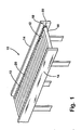
- a roller conveyor 10 comprises a plurality of idler rollers 12 rotatably mounted at opposite sidewalls 14 for conveying articles along conveyor 10 (FIG. 1).
- Rollers 12 are mountable to sidewalls 14 of conveyor 10 via at least one extendable and retractable stub axle or axle portion 22 extending from an axle bearing unit or stub axle unit or cartridge 24 at at least one end of the roller (FIG. 2).
- the idler rollers 12 include generally cylindrical roller portions 20 which generally freely rotate about the respective stub axles or axle portions 22 extending from opposite ends of the roller portions to convey articles along the roller conveyor.
- the stub axle 22 may include a generally conical-shaped outer end or tip 22d having one or more guide ribs or ridges 23 (FIGS. 6-11) to assist guiding and aligning the stub axle or axle portion with the corresponding opening in the sidewall of the conveyor during mounting of the roller to the conveyor, as discussed below.
- the idler rollers 12 may be gravity operated or driven by any type of drive system or device, such as, for example, one or more motorized rollers 16 and O-rings 18, or other types of driven rollers, tape drive systems or the like, to rotate the roller portion 20 relative to the stub axle or axles 22 to convey articles along the conveyor, without affecting the scope of the present invention.
- the roller portion 20 may comprise a generally cylindrical sleeve or tube or may comprise a sleeve or tube having varying diameters therealong, such as a tapered tube or a crowned tube or the like, without affecting the scope of the present invention.
- at least one end of the roller portion 20 receives the axle bearing unit or cartridge 24, whereby the stub axle 22 may extend longitudinally outwardly from the end of the roller portion for mounting the roller to the conveyor sidewall.
- Stub axle 22 may be extendable and retractable from the respective stub axle unit 24 to facilitate mounting of the respective idler roller 12 to the sidewalls 14 of conveyor 10.
- Each stub axle 22 includes an outer axle portion 22a, an inner axle portion 22b and a shoulder or raised portion 22c.
- outer axle portion 22a comprises a hexagonal-shaped portion
- inner axle portion 22b comprises a generally cylindrical portion.
- the hexagonal-shaped outer axle portion 22a may be formed to insert at least partially into and fit snugly within one of the correspondingly formed openings (not shown) in the conveyor sidewalls or within a mounting member or block or device (also not shown) positioned at the conveyor sidewall.
- the inner and/or outer axle portions may comprise other shapes, depending on the particular application of the stub axle units and rollers, and depending on the shape of the openings in the conveyor sidewalls or mounting member or device, without affecting the scope of the present invention.
- Each stub axle unit 24 includes a sleeve or housing 26, a bearing assembly 28 and stub axle 22.
- housing 26 of stub axle unit 24 is received within an end portion 20b of the outer roller portion or tube 20 of a roller, and may be press fit and frictionally retained within roller portion 20 or otherwise generally secured within the roller portion 20.
- Housing 26 may comprise a generally cylindrical and hollow housing having a generally open outer end 26a and an inner end 26b defining an inner support or support member 27, such as the wall or disc of the illustrated embodiment.
- the housing or shell 26 may be generally cylindrical and may have a narrowed or reduced diameter portion 26c for accommodating indentations or grooves 20a around roller portion 20 for receiving O-rings 18 or the like, as shown in FIG. 2, or may comprise a generally uniform cylindrical shape or any other shape or form that is receivable within the roller shell or tube, without affecting the scope of the present invention.
- Outer end 26a of housing 26 may receive bearing assembly 28 therein or may comprise one or more snap or attachment members 26d for fastening or attaching to bearing assembly 28 or to an outer adapter 32.
- Outer adapter 32 may include a raised outer lip or ridge 32a (FIGS. 2, 4 and 5) for limiting insertion of housing 26 and outer adapter 32 into roller portion 20.
- Outer adapter 32 receives bearing assembly 28 within and between a pair of raised ridges 32b, 32c to limit axial movement of bearing assembly 28 relative to outer adapter 32.
- bearing assembly 28 may comprise an outer race 28a, an inner race 28b and a plurality of balls 28c or the like to provide generally smooth and low friction rotation of outer race 28a about inner race 28b.
- Other forms of bearings or bearing assemblies may be implemented without affecting the scope of the present invention.
- Outer portion or race 28a of bearing assembly 28 may be substantially fixedly or non-rotatably secured or mounted to or integrally molded with outer adapter 32 at or near outer end 26a of housing 26, while inner portion or race 28b of bearing assembly 28 may also be substantially fixedly secured or mounted to or integrally molded with an inner adapter 30, so as to provide rotation of outer adapter 32 about inner adapter 30, and thus to provide rotation of housing 26 outer shell or tube or roller portion 20 around stub axle 22.
- inner adapter 30 may comprise opposite raised ends 30b, 30c to substantially preclude longitudinal or axial movement of inner adapter 30 relative to bearing assembly 28 and housing 26.
- Inner adapter 30 defines a generally hexagonal-shaped passageway 30a for slidably receiving outer axle portion 22a therethrough, such that outer axle portion 22a of stub axle 22 is non-rotatable and axially or longitudinally slidable relative to inner adapter 30.
- Shoulder 22c of stub axle 22 may engage inner end 30b of inner adapter 30 to limit outward extension of stub axle 22 and outer axle portion 22a relative to inner adapter 30 and, thus, relative to housing 26 of axle bearing unit 24, as can be seen in FIG. 2.
- the opposite end or inner axle portion 22b of stub axle extends inward from shoulder 22c and from inner adapter 30 and extends at least partially through support 27 of inner end 26b of housing 26.
- Support or support member or wall 27 at inner end 26b of housing 26 defines an opening or passageway 27a therethrough for at least partially receiving inner axle portion 22b, such that inner axle portion 22b extends at least partially through opening 27a in support 27.
- opening 27a has a larger diameter than the diameter of the generally cylindrical inner axle portion 22b, such that support 27 defines a gap circumferentially around the generally cylindrical inner axle portion 22b.
- Housing 26 thus may rotate around and be supported at stub axle 22 via bearing assembly 28, whereby inner support 27 does not contact inner axle portion 22b during normal use of the idler roller 12.
- roller portion 20 and housing 26 may flex or bend, whereby a portion of inner support 27 may close the gap and contact inner axle portion 22b.
- Inner support 27 thus may limit flexing or bending of the roller and/or binding of the bearing assembly 28 during such loading conditions.
- Stub axle 22 may be slidably or movably positioned within inner adapter 30 and is axially slidable between a retracted position and an extended position (shown in FIG. 2), where outer axle portion 22a extends outwardly from roller portion 20 for mounting stub axle 22 and roller 12 to the sidewalls 14 of the roller conveyor.
- Outer axle portion 22a may further include a conical-shaped tip or end 22d and one or more guide members 23 (FIGS. 4-8) to assist in guiding outer axle portion 22a into a respective hexagonal-shaped opening (not shown) in sidewall 14 of conveyor 10, as discussed below.
- Stub axle 22 may be biased toward the extended position, such as via a biasing member or spring 34 received or coiled around inner axle portion 22b and engaging shoulder 22c of stub axle 22 at one end and support or wall 27 of housing 26 at the other end, as shown in FIG. 2.
- Inner axle portion 22b extends at least partially through opening 27a in support 27 when stub axle 22 is in the extended position, while retraction or inward movement of stub axle 22 moves and inserts inner axle portion 22b further through opening 27a and compresses biasing member 34 while retracting outer axle portion 22a toward and at least partially into housing 26.
- housing 26 comprises a slotted sidewall, such as shown in FIG. 3, to ease assembly of stub axle 22 and biasing member 34 within housing 26 of stub axle unit 24.
- stub axle 22 may be pressed inward toward the retracted position to retract the outer axle portion 22a and outer tip 22d of stub axle 22 inward, whereby roller 12 may be positioned between the sidewalls of the conveyor.
- biasing member 34 biases or urges stub axle 22 outward to the extended position.
- outer end 22d of stub axle 22 inserts into the respective opening in the sidewall of the conveyor and may cause rotation of the stub axle to align the hexagonal-shaped outer axle portion with the correspondingly formed or shaped opening in the conveyor sidewall as the stub axle 22 extends and inserts further into the sidewall opening, as discussed in detail below.
- roller portion or sleeve 20 of roller 12 is freely rotatable about and supported at inner adapter 30 and stub axle 22 via bearing assembly 28.
- the circumferential gap 27b around inner axle portion 22b at inner support 27 of housing 26 provides for non-contacting rotation of housing 26 about stub axle 22 at support 27, such that the rotational support of roller portion 20 around and at stub axle 22 is provided by bearing assembly 28.
- roller portion 20 and/or housing 26 of axle bearing unit 24 may flex or bend such that a portion of support 27 contacts inner axle portion 22b and thus limits or substantially precludes further loading induced bending or flexing or deflection of housing 26 and roller portion 20.
- the inner support 27 thus may close the gap in response to overloading of the roller portion of the roller, wherein the overloading may be a load amount or force greater than a threshold amount of loading or force at the roller portion.
- the inner support 27 thus may provide non-contacting free rotation during normal operation of the roller and roller conveyor, while also providing contact support of the roller during excessive loading conditions of the roller, such as may occur if someone steps on the roller, such as during maintenance of the conveyor or the like.
- the inner support 27 thus may provide direct support to the roller portion at an area inwardly from the bearing assembly 28 at the outer end of the roller, such that the inner support may transfer the load directly to the roller portion or tube, such as in a direction generally transverse or perpendicular to the longitudinal axis of the roller.
- the direct support may be provided by the inner support of the housing, which may engage an inner surface of the roller portion generally at the inner support. Such direct support substantially limits bending or flexing or binding of the roller during such overloading conditions.
- inner axle portion 22b and/or inner support 27 at opening 27a may comprise smooth, low coefficient of friction surfaces to provide rotational movement of support 27 about inner axle portion 22b even when contact is made therebetween.
- the support 27 thus may provide rotational support of the roller portion about the stub axle even during high loading conditions, and may limit or substantially preclude further bending or flexing of the roller and, thus, may limit or substantially preclude binding of the bearing assembly 28 during such loading conditions.
- outer end or tip 22d of outer axle portion 22a may comprise a generally tapered or conical-shaped tip or end and preferably includes at least one guiding or aligning rib or ridge or member 23 extending along and protruding from the conical or rounded surface of the end 22d.
- Guide members 23 may comprise generally straight ribs or ridges extending along the generally tapered or conical-shaped surface of end 22d of outer axle portion 22a and function to engage the walls of the opening in the sidewall of the conveyor, particularly at the corners of a hexagonal-shaped opening or the like, and to twist or rotate the axle portion as the axle end is inserted into the opening, so as to align the generally hexagonal-shaped axle portion with the correspondingly shaped or formed opening in the sidewall of the conveyor.
- the conical-shaped end 22d may narrow to a generally rounded tip or point, with the aligning members 23 extending along the conical surface generally between the tip or end of the axle and a point or corner 22e of the hexagonal-shaped outer axle portion 22a of stub axle 22.
- Alignment members 23 may be skewed or not aligned with the longitudinal axis of the axle or axle portion, as can be seen with reference to FIGS. 6 and 7. In other words, the alignment members 23 may not be along or within a plane bisecting the axle portion along the longitudinal axis of the axle portion, such as a plane 25 (FIG. 7) bisecting the axle portion along the longitudinal axis 27 (FIG.
- the alignment members 23 thus may engage the walls of the opening in the conveyor sidewall and may cause rotation of the axle portion to align with the respective opening in the sidewall as the axle tip is inserted into and at least partially through the opening in the conveyor sidewall.
- the alignment members 23 may be generally rounded, as best shown in FIGS. 7 and 8, to limit or substantially preclude binding of the axle tip as it is inserted into and aligned within the opening in the conveyor sidewall.
- the axle end thus may have a generally circular cross-section with one or more spaced apart and raised and rounded projections or ribs extending along the surface of the axle end or tip.
- two alignment members 23 are arranged along the surface of the tip and are positioned at an angle relative to one another of approximately 60 degrees, such that the ribs or members extend to adjacent corners or points 22e of the hexagonal-shaped or formed outer axle portion.
- other arrangements of one or more alignment members may be implemented along an outer end or tip of an axle portion, such as a pair of alignment members 23' positioned or formed along an outer tip or end 22d' of an outer axle portion 22a' and arranged at an angle relative to one another of approximately 120 degrees, as shown in FIGS. 9-11, or other arrangements, without affecting the scope of the present invention.
- the axle tip and alignment ridges or ribs or members thus function to engage the walls, and particularly the corners of the walls, of the respective opening in the conveyor sidewall and to rotate the axle portion to guide the points or corners of the hexagonal outer axle portion into alignment with the corresponding corners of the opening in the conveyor sidewall.
- the rotation and alignment of the stub axle or axle portion may occur as the stub axle is extended or urged outward from the axle bearing unit via the biasing member. Because the guide or alignment ribs or members may be rounded, the ribs may smoothly slide into and along the walls of the openings without binding in the corners or against the flat walls of the opening.
- the conical-shaped end or tip and alignment members or ribs of the present invention may be implemented at the outer end of stub axles or the like of other axle cartridges or units or at the outer end of other types of axles or axle portions, without affecting the scope of the present invention.
- the axle bearing unit or assembly of the present invention provides for rotational support of the roller portion of a conveyor roller about the stub axle or axle portion via a single bearing assembly, while limiting or substantially precluding flexing or bending of the roller and/or binding of the bearing assembly during loading of the roller above a normal or threshold amount.
- the support or wall of the housing of the axle bearing unit may engage the stub axle to limit bending or flexing of the roller portion and/or housing during such loading conditions.
- the axle bearing unit thus provides enhanced rotational support of the roller while substantially avoiding binding of or damage to the bearing assembly during excessive loading conditions.
- the present invention provides an axle end or tip of an axle or axle portion of a conveyor roller which engages a respective opening in a sidewall of the conveyor or in a mounting member or device at a sidewall of the conveyor.
- the axle end or tip may cause rotation of the axle or axle portion to align the shape or form of the axle or axle portion with the corresponding shape or form of the opening.
- the axle end includes one or more alignment ribs or guides or members positioned along and protruding from a generally conical surface of the axle end or tip.
- the alignment members engage the walls of the conveyor sidewall or mounting device around the respective opening and may cause rotation of the axle or axle portion to align the axle shape or form with the shape or form of the opening as the axle end is inserted into and at least partially through the opening in the conveyor sidewall or mounting device.
Landscapes
- Engineering & Computer Science (AREA)
- General Engineering & Computer Science (AREA)
- Mechanical Engineering (AREA)
- Rollers For Roller Conveyors For Transfer (AREA)
- Rolls And Other Rotary Bodies (AREA)
Description
- The present invention relates generally to conveyor rollers and, more particularly, to axle cartridges or stub axles or axle bearing units or inserts for conveyor rollers for rotatably mounting the ends or axles of a conveyor roller to the sidewalls of the conveyor.
- It is known in the roller conveyor art to mount rollers at and between the sidewalls of a conveyor frame. The rollers typically include an axle or opposite axle portions which extend into openings in the sidewalls. The rollers may have a generally cylindrical roller portion or tapered roller portion or crowned roller portion or the like which is rotatable relative to the axle or axle portions. It is also known to provide an axle bearing unit or cartridge or insert at one or both ends of a roller which provides for rotational movement of the roller portion about the respective stub axle or stub axles extending from the axle bearing unit or units. The stub axle may be spring-loaded or biased to facilitate retraction of the stub axle and to bias the stub axle to extend outwardly from the axle bearing unit for insertion into the openings in the sidewalls.
- To ease insertion of the stub axle, which typically has a hexagonal-shaped cross section for insertion into a correspondingly formed hexagonally-shaped opening in the conveyor sidewall, it is known to provide a tapered end or tip at the outer end of the stub axle. The tapered end portion may also have a hexagonal-shaped cross section and may guide the stub axle into the opening and generally align the stub axle with the walls of the opening. Such a stub axle is shown, for example, in
US-A-5 875 878 . - The present invention provides an axle bearing unit or cartridge for positioning at one or both ends of a roller portion. The axle bearing unit provides an axle portion or stub axle with guide members or ribs or ridges extending along a conical-shaped tip or end portion of the stub axle for aligning the stub axle shape or form with the correspondingly formed opening in the sidewall of the conveyor. The axle bearing unit also provides for rotational support of the roller portion about the stub axle via a bearing assembly at one end of the stub axle and further provides a support wall or member for limiting flexing or bending of the roller portion relative to the stub axle. The support member may be circumferentially spaced around the stub axle during normal operation and may contact a portion of the stub axle to limit further flexing or bending of the roller portion in response to loading of the roller portion of the conveyor roller.
- According to an aspect of the present invention, an axle bearing unit or assembly or cartridge is configured to be received within an end of a roller tube or sleeve or portion of a conveyor roller. The axle bearing cartridge comprises a housing adapted to be inserted at least partially into an end of the roller portion, a stub axle or axle portion positioned partially within the housing, and a bearing assembly positioned generally at the outer end of the housing and between the stub axle and the housing to provide for rotational support of the housing about the stub axle. An inner end of the housing comprises an inner support or support member or wall. The stub axle has a longitudinal axis and extends at least partially through the inner support such that the inner support defines a gap circumferentially around the stub axle. The inner support of the housing may define the circumferential gap during operation of the roller conveyor, while a portion of the inner support may close the gap and provide contact support for the stub axle in response to loading induced deflection generally at the inner end of the housing in a direction generally normal to the longitudinal axis of the stub axle.
- The inner support of the housing may define the circumferential gap during normal operation of the roller conveyor, while the portion of the inner support may close the gap in response to overloading of the roller portion of the roller, wherein the overloading may be greater than a threshold amount of loading of the roller portion.
- In one form, the inner support defines an inner wall at the inner end of the housing. The inner wall defines an inner opening therethrough for receiving the stub axle at least partially therethrough. The inner opening has a diameter which is greater than a diameter of an inner axle portion of the stub axle, which may comprise a generally cylindrical inner axle portion.
- In one form, an outer axle portion comprises a hexagonal-shaped cross section and a generally conical-shaped outer end. The conical-shaped outer end may comprise at least one raised rib therealong. The raised rib or ribs may be arranged on the conical-shaped outer end to be skewed or non-parallel to a plane bisecting the stub axle along the longitudinal axis of the stub axle. In other words, the raised rib or ribs may be arranged non-longitudinally along the generally conical surface of the generally conical-shaped outer end of the stub axle.
- According to another aspect of the present invention, a conveyor roller for mounting at and between opposite sidewalls of a conveyor comprises a roller tube or sleeve or portion and an axle portion positioned at least partially within the roller portion and rotatable relative thereto. The axle portion defines a longitudinal axis and extends from at least one end of the roller portion. The axle portion has a generally tapered or conical-shaped outer axle end defining a generally tapered or conical-shaped surface. The outer axle end has at least one raised rib positioned along the generally conical-shaped surface of the axle end for aligning the axle portion with a respective correspondingly formed opening in a sidewall of the conveyor.
- The rib or ribs may have a generally rounded cross section. The raised rib or ribs is/are arranged to be non-parallel or skewed relative to a plane bisecting the axle portion along the longitudinal axis of the axle portion. The raised ribs may comprise generally straight ribs extending along the conical-shaped surface and may define an angle between them, such as an angle of approximately 60 degrees or 120 degrees or other desired angle.
- The axle portion may be axially movable relative to the roller portion between an extended position and a retracted position to ease mounting of the roller to the conveyor sidewalls. In one form, the axle portion is slidably mounted at an axle bearing unit positioned at least partially within the roller portion. The axle bearing unit may comprise a housing adapted to be inserted at least partially into the roller portion and comprising an inner support defining an opening at an inner end of the housing. The axle portion extends at least partially through the opening, wherein the opening defines a gap generally circumferentially around the axle portion. A portion of the support of the housing may close the gap and contact the axle portion in response to loading of the roller portion in a direction generally normal to a longitudinal axis of the axle portion.
- Therefore, the present invention provides an outer axle end of an axle portion which engages a respective opening in the sidewall of the conveyor and may cause rotation of the axle portion to align the form or shape of the axle portion with the corresponding form or shape of the opening. The outer axle end may include one or more alignment ribs or guides or members positioned along and protruding from a generally conical surface. The alignment members engage the conveyor sidewall around the respective opening and may cause rotation of the axle portion to align the axle portion with the opening as the outer axle end and axle portion are inserted into and at least partially through the opening in the conveyor sidewall.
- These and other objects, advantages, purposes and features of the present invention will become apparent upon review of the following specification in conjunction with the drawings.
-
- FIG. 1 is an upper perspective view of a conveyor having rollers which include an axle bearing unit or cartridge in accordance with the present invention;
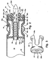
- FIG. 2 is a sectional view of an end portion of one of the rollers and axle cartridges of the present invention;
- FIG. 3 is a perspective view of a housing portion of the axle cartridge of FIG. 2;
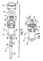
- FIG. 4 is a perspective view of an axle cartridge of the present invention;
- FIG. 5 is an exploded perspective view of the axle cartridge of FIG. 4;
- FIG. 6 is a perspective view of an end of an axle portion in accordance with the present invention;
- FIG. 7 is an end view of the axle portion of FIG. 6;
- FIG. 8 is a sectional view taken along the line VIII-VIII in FIG. 6;
- FIG. 9 is a perspective view of an end of another axle portion in accordance with the present invention;
- FIG. 10 is an end view of the axle portion of FIG. 9; and
- FIG. 11 is a sectional view taken along the line XI-XI in FIG. 9.
- Referring now specifically to the drawings and the illustrative embodiments depicted therein, a
roller conveyor 10 comprises a plurality ofidler rollers 12 rotatably mounted atopposite sidewalls 14 for conveying articles along conveyor 10 (FIG. 1).Rollers 12 are mountable tosidewalls 14 ofconveyor 10 via at least one extendable and retractable stub axle oraxle portion 22 extending from an axle bearing unit or stub axle unit orcartridge 24 at at least one end of the roller (FIG. 2). Theidler rollers 12 include generallycylindrical roller portions 20 which generally freely rotate about the respective stub axles oraxle portions 22 extending from opposite ends of the roller portions to convey articles along the roller conveyor. Thestub axle 22 may include a generally conical-shaped outer end ortip 22d having one or more guide ribs or ridges 23 (FIGS. 6-11) to assist guiding and aligning the stub axle or axle portion with the corresponding opening in the sidewall of the conveyor during mounting of the roller to the conveyor, as discussed below. - The
idler rollers 12 may be gravity operated or driven by any type of drive system or device, such as, for example, one or moremotorized rollers 16 and O-rings 18, or other types of driven rollers, tape drive systems or the like, to rotate theroller portion 20 relative to the stub axle oraxles 22 to convey articles along the conveyor, without affecting the scope of the present invention. Theroller portion 20 may comprise a generally cylindrical sleeve or tube or may comprise a sleeve or tube having varying diameters therealong, such as a tapered tube or a crowned tube or the like, without affecting the scope of the present invention. As shown in FIG. 2, at least one end of theroller portion 20 receives the axle bearing unit orcartridge 24, whereby thestub axle 22 may extend longitudinally outwardly from the end of the roller portion for mounting the roller to the conveyor sidewall. -
Stub axle 22 may be extendable and retractable from the respectivestub axle unit 24 to facilitate mounting of therespective idler roller 12 to thesidewalls 14 ofconveyor 10. Eachstub axle 22 includes anouter axle portion 22a, aninner axle portion 22b and a shoulder or raisedportion 22c. In the illustrated embodiments,outer axle portion 22a comprises a hexagonal-shaped portion, whileinner axle portion 22b comprises a generally cylindrical portion. The hexagonal-shapedouter axle portion 22a may be formed to insert at least partially into and fit snugly within one of the correspondingly formed openings (not shown) in the conveyor sidewalls or within a mounting member or block or device (also not shown) positioned at the conveyor sidewall. However, the inner and/or outer axle portions may comprise other shapes, depending on the particular application of the stub axle units and rollers, and depending on the shape of the openings in the conveyor sidewalls or mounting member or device, without affecting the scope of the present invention. - Each
stub axle unit 24 includes a sleeve orhousing 26, a bearingassembly 28 andstub axle 22. As shown in FIG. 2,housing 26 ofstub axle unit 24 is received within anend portion 20b of the outer roller portion ortube 20 of a roller, and may be press fit and frictionally retained withinroller portion 20 or otherwise generally secured within theroller portion 20.Housing 26 may comprise a generally cylindrical and hollow housing having a generally openouter end 26a and aninner end 26b defining an inner support orsupport member 27, such as the wall or disc of the illustrated embodiment. The housing orshell 26 may be generally cylindrical and may have a narrowed or reduceddiameter portion 26c for accommodating indentations orgrooves 20a aroundroller portion 20 for receiving O-rings 18 or the like, as shown in FIG. 2, or may comprise a generally uniform cylindrical shape or any other shape or form that is receivable within the roller shell or tube, without affecting the scope of the present invention. -
Outer end 26a ofhousing 26 may receive bearingassembly 28 therein or may comprise one or more snap orattachment members 26d for fastening or attaching to bearingassembly 28 or to anouter adapter 32.Outer adapter 32 may include a raised outer lip orridge 32a (FIGS. 2, 4 and 5) for limiting insertion ofhousing 26 andouter adapter 32 intoroller portion 20.Outer adapter 32 receives bearingassembly 28 within and between a pair of raisedridges assembly 28 relative toouter adapter 32. - As shown in FIGS. 2 and 4, bearing
assembly 28 may comprise anouter race 28a, aninner race 28b and a plurality ofballs 28c or the like to provide generally smooth and low friction rotation ofouter race 28a aboutinner race 28b. Other forms of bearings or bearing assemblies may be implemented without affecting the scope of the present invention. Outer portion orrace 28a of bearingassembly 28 may be substantially fixedly or non-rotatably secured or mounted to or integrally molded withouter adapter 32 at or nearouter end 26a ofhousing 26, while inner portion orrace 28b of bearingassembly 28 may also be substantially fixedly secured or mounted to or integrally molded with aninner adapter 30, so as to provide rotation ofouter adapter 32 aboutinner adapter 30, and thus to provide rotation ofhousing 26 outer shell or tube orroller portion 20 aroundstub axle 22. - As best shown in FIGS. 2, 4 and 5,
inner adapter 30 may comprise opposite raised ends 30b, 30c to substantially preclude longitudinal or axial movement ofinner adapter 30 relative to bearingassembly 28 andhousing 26.Inner adapter 30 defines a generally hexagonal-shapedpassageway 30a for slidably receivingouter axle portion 22a therethrough, such thatouter axle portion 22a ofstub axle 22 is non-rotatable and axially or longitudinally slidable relative toinner adapter 30.Shoulder 22c ofstub axle 22 may engageinner end 30b ofinner adapter 30 to limit outward extension ofstub axle 22 andouter axle portion 22a relative toinner adapter 30 and, thus, relative tohousing 26 ofaxle bearing unit 24, as can be seen in FIG. 2. The opposite end orinner axle portion 22b of stub axle extends inward fromshoulder 22c and frominner adapter 30 and extends at least partially throughsupport 27 ofinner end 26b ofhousing 26. - Support or support member or
wall 27 atinner end 26b ofhousing 26 defines an opening orpassageway 27a therethrough for at least partially receivinginner axle portion 22b, such thatinner axle portion 22b extends at least partially throughopening 27a insupport 27. As can be seen in FIG. 2,opening 27a has a larger diameter than the diameter of the generally cylindricalinner axle portion 22b, such thatsupport 27 defines a gap circumferentially around the generally cylindricalinner axle portion 22b.Housing 26 thus may rotate around and be supported atstub axle 22 via bearingassembly 28, wherebyinner support 27 does not contactinner axle portion 22b during normal use of theidler roller 12. However, during excessive loading of theroller portion 20 at a location along the roller portion generally laterally inward of bearingassembly 28 ofaxle bearing unit 24, theroller portion 20 andhousing 26 may flex or bend, whereby a portion ofinner support 27 may close the gap and contactinner axle portion 22b.Inner support 27 thus may limit flexing or bending of the roller and/or binding of the bearingassembly 28 during such loading conditions. -
Stub axle 22 may be slidably or movably positioned withininner adapter 30 and is axially slidable between a retracted position and an extended position (shown in FIG. 2), whereouter axle portion 22a extends outwardly fromroller portion 20 for mountingstub axle 22 androller 12 to thesidewalls 14 of the roller conveyor.Outer axle portion 22a may further include a conical-shaped tip or end 22d and one or more guide members 23 (FIGS. 4-8) to assist in guidingouter axle portion 22a into a respective hexagonal-shaped opening (not shown) insidewall 14 ofconveyor 10, as discussed below.Stub axle 22 may be biased toward the extended position, such as via a biasing member orspring 34 received or coiled aroundinner axle portion 22b and engagingshoulder 22c ofstub axle 22 at one end and support orwall 27 ofhousing 26 at the other end, as shown in FIG. 2.Inner axle portion 22b extends at least partially throughopening 27a insupport 27 whenstub axle 22 is in the extended position, while retraction or inward movement ofstub axle 22 moves and insertsinner axle portion 22b further throughopening 27a and compresses biasingmember 34 while retractingouter axle portion 22a toward and at least partially intohousing 26. In the illustrated embodiment,housing 26 comprises a slotted sidewall, such as shown in FIG. 3, to ease assembly ofstub axle 22 and biasingmember 34 withinhousing 26 ofstub axle unit 24. - During mounting or installation of
roller 12 to sidewalls 14,stub axle 22 may be pressed inward toward the retracted position to retract theouter axle portion 22a andouter tip 22d ofstub axle 22 inward, wherebyroller 12 may be positioned between the sidewalls of the conveyor. Whenstub axle 22 is released, biasingmember 34 biases or urgesstub axle 22 outward to the extended position. Asstub axle 22 extends,outer end 22d ofstub axle 22 inserts into the respective opening in the sidewall of the conveyor and may cause rotation of the stub axle to align the hexagonal-shaped outer axle portion with the correspondingly formed or shaped opening in the conveyor sidewall as thestub axle 22 extends and inserts further into the sidewall opening, as discussed in detail below. - When
roller 12 is installed at thesidewalls 14 ofconveyor 10, roller portion orsleeve 20 ofroller 12 is freely rotatable about and supported atinner adapter 30 andstub axle 22 via bearingassembly 28. During normal operation and use ofroller 12 andconveyor 10, the circumferential gap 27b aroundinner axle portion 22b atinner support 27 ofhousing 26 provides for non-contacting rotation ofhousing 26 aboutstub axle 22 atsupport 27, such that the rotational support ofroller portion 20 around and atstub axle 22 is provided by bearingassembly 28. However, if excessive loading ofroller 12 occurs, such as increased loading at thecylindrical portion 20 orinner end 26b ofhousing 26 in a direction generally normal to the longitudinal axis of the axle,roller portion 20 and/orhousing 26 ofaxle bearing unit 24 may flex or bend such that a portion ofsupport 27 contactsinner axle portion 22b and thus limits or substantially precludes further loading induced bending or flexing or deflection ofhousing 26 androller portion 20. Theinner support 27 thus may close the gap in response to overloading of the roller portion of the roller, wherein the overloading may be a load amount or force greater than a threshold amount of loading or force at the roller portion. - The
inner support 27 thus may provide non-contacting free rotation during normal operation of the roller and roller conveyor, while also providing contact support of the roller during excessive loading conditions of the roller, such as may occur if someone steps on the roller, such as during maintenance of the conveyor or the like. Theinner support 27 thus may provide direct support to the roller portion at an area inwardly from the bearingassembly 28 at the outer end of the roller, such that the inner support may transfer the load directly to the roller portion or tube, such as in a direction generally transverse or perpendicular to the longitudinal axis of the roller. The direct support may be provided by the inner support of the housing, which may engage an inner surface of the roller portion generally at the inner support. Such direct support substantially limits bending or flexing or binding of the roller during such overloading conditions. - Optionally,
inner axle portion 22b and/orinner support 27 atopening 27a may comprise smooth, low coefficient of friction surfaces to provide rotational movement ofsupport 27 aboutinner axle portion 22b even when contact is made therebetween. Thesupport 27 thus may provide rotational support of the roller portion about the stub axle even during high loading conditions, and may limit or substantially preclude further bending or flexing of the roller and, thus, may limit or substantially preclude binding of the bearingassembly 28 during such loading conditions. - Referring now to FIGS. 6-8, outer end or
tip 22d ofouter axle portion 22a may comprise a generally tapered or conical-shaped tip or end and preferably includes at least one guiding or aligning rib or ridge ormember 23 extending along and protruding from the conical or rounded surface of theend 22d.Guide members 23 may comprise generally straight ribs or ridges extending along the generally tapered or conical-shaped surface ofend 22d ofouter axle portion 22a and function to engage the walls of the opening in the sidewall of the conveyor, particularly at the corners of a hexagonal-shaped opening or the like, and to twist or rotate the axle portion as the axle end is inserted into the opening, so as to align the generally hexagonal-shaped axle portion with the correspondingly shaped or formed opening in the sidewall of the conveyor. - As shown in FIGS. 6 and 7, the conical-shaped
end 22d may narrow to a generally rounded tip or point, with the aligningmembers 23 extending along the conical surface generally between the tip or end of the axle and a point orcorner 22e of the hexagonal-shapedouter axle portion 22a ofstub axle 22.Alignment members 23 may be skewed or not aligned with the longitudinal axis of the axle or axle portion, as can be seen with reference to FIGS. 6 and 7. In other words, thealignment members 23 may not be along or within a plane bisecting the axle portion along the longitudinal axis of the axle portion, such as a plane 25 (FIG. 7) bisecting the axle portion along the longitudinal axis 27 (FIG. 6) and extending betweenopposite corners 22e of the hexagonal-shaped (or other shape, depending on the application) axle portion. Thealignment members 23 thus may engage the walls of the opening in the conveyor sidewall and may cause rotation of the axle portion to align with the respective opening in the sidewall as the axle tip is inserted into and at least partially through the opening in the conveyor sidewall. Thealignment members 23 may be generally rounded, as best shown in FIGS. 7 and 8, to limit or substantially preclude binding of the axle tip as it is inserted into and aligned within the opening in the conveyor sidewall. As can be seen with reference to FIG. 8, the axle end thus may have a generally circular cross-section with one or more spaced apart and raised and rounded projections or ribs extending along the surface of the axle end or tip. - In the illustrated embodiment of FIGS. 6-8, two
alignment members 23 are arranged along the surface of the tip and are positioned at an angle relative to one another of approximately 60 degrees, such that the ribs or members extend to adjacent corners orpoints 22e of the hexagonal-shaped or formed outer axle portion. Optionally, other arrangements of one or more alignment members may be implemented along an outer end or tip of an axle portion, such as a pair ofalignment members 23' positioned or formed along an outer tip or end 22d' of anouter axle portion 22a' and arranged at an angle relative to one another of approximately 120 degrees, as shown in FIGS. 9-11, or other arrangements, without affecting the scope of the present invention. - The axle tip and alignment ridges or ribs or members thus function to engage the walls, and particularly the corners of the walls, of the respective opening in the conveyor sidewall and to rotate the axle portion to guide the points or corners of the hexagonal outer axle portion into alignment with the corresponding corners of the opening in the conveyor sidewall. The rotation and alignment of the stub axle or axle portion may occur as the stub axle is extended or urged outward from the axle bearing unit via the biasing member. Because the guide or alignment ribs or members may be rounded, the ribs may smoothly slide into and along the walls of the openings without binding in the corners or against the flat walls of the opening. Although shown and described as being implemented along an outer end or tip of a stub axle for the axle cartridge or
unit 24, the conical-shaped end or tip and alignment members or ribs of the present invention may be implemented at the outer end of stub axles or the like of other axle cartridges or units or at the outer end of other types of axles or axle portions, without affecting the scope of the present invention. - Although aspects of the present invention are shown and described above with respect to particular embodiments, it is envisioned that the various aspects described herein may be used alone or in combination with other aspects of the present invention on various roller embodiments, without affecting the scope of the present invention.
- Therefore, the axle bearing unit or assembly of the present invention provides for rotational support of the roller portion of a conveyor roller about the stub axle or axle portion via a single bearing assembly, while limiting or substantially precluding flexing or bending of the roller and/or binding of the bearing assembly during loading of the roller above a normal or threshold amount. The support or wall of the housing of the axle bearing unit may engage the stub axle to limit bending or flexing of the roller portion and/or housing during such loading conditions. The axle bearing unit thus provides enhanced rotational support of the roller while substantially avoiding binding of or damage to the bearing assembly during excessive loading conditions.
- Also, the present invention provides an axle end or tip of an axle or axle portion of a conveyor roller which engages a respective opening in a sidewall of the conveyor or in a mounting member or device at a sidewall of the conveyor. The axle end or tip may cause rotation of the axle or axle portion to align the shape or form of the axle or axle portion with the corresponding shape or form of the opening. The axle end includes one or more alignment ribs or guides or members positioned along and protruding from a generally conical surface of the axle end or tip. The alignment members engage the walls of the conveyor sidewall or mounting device around the respective opening and may cause rotation of the axle or axle portion to align the axle shape or form with the shape or form of the opening as the axle end is inserted into and at least partially through the opening in the conveyor sidewall or mounting device.
- Changes and modifications in the specifically described embodiments can be carried out without departing from the principles of the present invention, which is intended to be limited only by the scope of the appended claims, as interpreted according to the principles of patent law.
Claims (11)
- A conveyor roller (12) for mounting at and between opposite sidewalls of a conveyor, said conveyor roller comprising:a roller portion (20); andan axle portion (22) positioned at least partially within said roller portion and rotatable relative thereto, said axle portion defining a longitudinal axis and extending from at least one end of said roller portion, said axle portion having a generally conical-shaped axle end (22d) defining a generally conical-shaped surface, characterized in that said axle end has at least one raised rib (23) positioned along said generally conical-shaped surface of said axle end and said at least one rib (23) is raised in respect to said generally conical-shaped surface.
- The conveyor roller of claim 1, wherein said at least one raised rib is arranged to be skewed relative to a plane bisecting said axle portion along said longitudinal axis.
- The conveyor roller of claim 2, wherein said axle portion has a hexagonal-shaped cross-section, said at least on raised rib extending from a tip region of said conical-shaped axle and toward a corner of said hexagonal-shaped axle portion, said at least one raised rib being skewed relative to a plane bisecting said axle portion along said longitudinal axis of said axle portion and between opposite corners of said hexagonal-shaped axle portion.
- The conveyor roller of claim 1, wherein said at least one raised rib comprises a generally straight rib extending along said conical-shaped surface.
- The conveyor roller of claim 1, wherein said at least one raised rib comprises a pair of raised ribs positioned along said generally conical-shaped surface.
- The conveyor roller of claim 1, wherein said pair of raised ribs are arranged to be skewed relative to a plane bisecting said axle portion along said longitudinal axis.
- The conveyor roller of claim 6, wherein said pair of raised ribs are arranged to define an angle between them.
- The conveyor roller of claim 1, wherein said at least one rib comprises a generally rounded cross section.
- The conveyor roller of claim 1, wherein said axle portion is axially movable relative to said cylindrical roller portion and is movably mounted at an axle bearing unit (24) positioned within said roller portion.
- The conveyor roller of claim 9, wherein said axle bearing unit comprises a housing (26) adapted to be inserted at least partially into said roller portion, said housing comprising an Inner support (27) at an inner end portion of said housing, said axle portion extending at least partially through said inner support, said inner support defining a gap circumferentially around said axle portion.
- The conveyor roller of claim 10, wherein a portion of said inner support closes a portion of said circumferential gap and provides contact support of said axle portion in response to loading induced deflection at said inner end of said housing in a direction generally normal to said longitudinal axis of said axle portion.
Applications Claiming Priority (3)
| Application Number | Priority Date | Filing Date | Title |
|---|---|---|---|
| US365804 | 2003-02-13 | ||
| US10/365,804 US6782996B1 (en) | 2003-02-13 | 2003-02-13 | Axle cartridge for conveyor roller |
| PCT/US2004/004212 WO2004071908A2 (en) | 2003-02-13 | 2004-02-12 | Axle cartridge for conveyor roller |
Publications (2)
| Publication Number | Publication Date |
|---|---|
| EP1592629A2 EP1592629A2 (en) | 2005-11-09 |
| EP1592629B1 true EP1592629B1 (en) | 2007-11-14 |
Family
ID=32849657
Family Applications (1)
| Application Number | Title | Priority Date | Filing Date |
|---|---|---|---|
| EP04710676A Expired - Lifetime EP1592629B1 (en) | 2003-02-13 | 2004-02-12 | Axle cartridge for conveyor roller |
Country Status (5)
| Country | Link |
|---|---|
| US (1) | US6782996B1 (en) |
| EP (1) | EP1592629B1 (en) |
| CA (1) | CA2515770A1 (en) |
| DE (1) | DE602004010070D1 (en) |
| WO (1) | WO2004071908A2 (en) |
Families Citing this family (22)
| Publication number | Priority date | Publication date | Assignee | Title |
|---|---|---|---|---|
| EP1123246A4 (en) | 1998-07-31 | 2003-04-09 | Shuttleworth Inc | Low electrostatic discharge conveyor |
| JP2003335430A (en) * | 2002-03-14 | 2003-11-25 | Seiko Epson Corp | Discharge roller, method of manufacturing the same, and recording apparatus |
| US20060050127A1 (en) * | 2002-03-14 | 2006-03-09 | Seiko Epson Corporation | Recording apparatus |
| US7181845B2 (en) * | 2003-02-28 | 2007-02-27 | Bryant Products, Inc. | Roller with integral bearing assembly mount and method for manufacturing same |
| GB2407247A (en) * | 2003-10-22 | 2005-04-27 | Cnh Belgium Nv | Anti-wrapping device for a combine harvester reel |
| US7028825B2 (en) * | 2004-04-02 | 2006-04-18 | Scott C Winfield | Conveyor roller assembly, conveyor roller insert and axle for conveyor roller |
| US7048112B2 (en) * | 2004-09-27 | 2006-05-23 | Formigoni Jonathan E | Food grade conveyor |
| WO2006063012A2 (en) * | 2004-12-08 | 2006-06-15 | Portec Inc. | Motorized pulley |
| US20070261933A1 (en) * | 2006-04-26 | 2007-11-15 | Scott C W | Conveyor roller assembly and conveyor roller insert |
| US7503450B2 (en) * | 2007-08-13 | 2009-03-17 | Magstar Technologies, Inc. | Long roller slip conveyor |
| US20090045029A1 (en) * | 2007-08-16 | 2009-02-19 | Deur Delwyn G | Conveyor roller and cartridge bearing assembly for same |
| DE102008013131B4 (en) * | 2008-03-07 | 2015-12-31 | Ab Skf | Bearing arrangement for a carrying roller |
| US8820853B1 (en) | 2010-03-25 | 2014-09-02 | Eko Sport, Inc. | Wheel axle assembly |
| US8439573B2 (en) | 2011-02-21 | 2013-05-14 | Peter Zuiko | Replaceable bearing for a conveyor roller |
| US8672116B2 (en) * | 2011-09-23 | 2014-03-18 | Bastian Automation Engineering, Llc | Sprung pin conveyor roller bearing |
| DE202012008919U1 (en) * | 2012-09-18 | 2014-01-22 | Interroll-Holding Ag | Conveyor roller with head element |
| US20140348457A1 (en) * | 2013-05-23 | 2014-11-27 | Schaeffler Technologies Gmbh & Co. Kg | Bearing mounting collar |
| DE102013107869A1 (en) * | 2013-07-23 | 2015-01-29 | Thyssenkrupp Fahrtreppen Gmbh | Escalator or moving walk |
| US9676553B2 (en) | 2013-09-06 | 2017-06-13 | Matthew Earl Wallace | Conveyor roller with integral clutch |
| US10472179B2 (en) | 2017-03-09 | 2019-11-12 | Lewco, Inc. | Cartridge bearing assembly for roller conveyors |
| US10583992B2 (en) | 2018-02-23 | 2020-03-10 | Frantz Manufacturing Company | Stub axles conveyor rollers |
| US12497242B2 (en) | 2023-11-03 | 2025-12-16 | Frantz Manufacturing Company | Spring-loaded bearing assembly |
Family Cites Families (99)
| Publication number | Priority date | Publication date | Assignee | Title |
|---|---|---|---|---|
| US1726720A (en) | 1929-09-03 | Curtain roller | ||
| US413420A (en) * | 1889-10-22 | Signors op one-third to joseph p | ||
| US434295A (en) | 1890-08-12 | Rolling-pin | ||
| US17368A (en) | 1857-05-26 | Cttrtansr-iloller | ||
| US1136089A (en) | 1908-10-31 | 1915-04-20 | Alvey Ferguson Co | Friction-reducing bearing. |
| US980523A (en) | 1909-02-05 | 1911-01-03 | Minnesota Manufacturers Ass | Carrier. |
| DE413420C (en) * | 1916-10-10 | 1925-05-08 | Guarantee Liquid Measure Compa | Device for dispensing fluids in measured quantities |
| BE356247A (en) | 1927-12-08 | |||
| US1752020A (en) | 1928-05-16 | 1930-03-25 | Peter J Mitchels | Connection for drapery rods |
| US1919495A (en) | 1930-12-05 | 1933-07-25 | Lamson Co | Conveyer |
| US1949817A (en) | 1931-10-08 | 1934-03-06 | Logan Co Inc | Roller conveyer |
| US1928549A (en) | 1932-10-03 | 1933-09-26 | Mcfall Co Carey | Roller trunnion and process of making the same |
| US1971995A (en) | 1932-10-03 | 1934-08-28 | Mcfall Co Carey | Curtain roller |
| US2024024A (en) | 1934-03-05 | 1935-12-10 | Duraloy Company | Furnace conveyer shaft |
| US2152076A (en) | 1936-07-15 | 1939-03-28 | Michiana Products Corp | High temperature shaft or roll |
| BE422755A (en) | 1936-07-23 | |||
| US2696283A (en) | 1949-08-22 | 1954-12-07 | Harry W Barry | Roller conveyer construction |
| US2622720A (en) | 1950-09-07 | 1952-12-23 | United States Steel Corp | Roller conveyer |
| US2699953A (en) | 1950-10-26 | 1955-01-18 | Harry F Chaddick | Dolly frame supported on rollers |
| FR1107271A (en) | 1956-06-22 | 1955-12-29 | Conveyor roller | |
| US3002792A (en) | 1958-11-20 | 1961-10-03 | Mathews Conveyer Co | Roller conveyer structure |
| US3258097A (en) | 1964-05-13 | 1966-06-28 | Mallard Plastics Inc | Low friction flow roller assembly |
| US3368231A (en) | 1964-08-19 | 1968-02-13 | Gen Electric | Portable electric clothes cleaner |
| AT254043B (en) | 1965-04-29 | 1967-05-10 | Karl Schultz Fa | Roller for roller conveyors and conveyor belts |
| US3353644A (en) | 1966-01-24 | 1967-11-21 | Colonial Plastics Mfg Co | Roller for a conveyor |
| US3402802A (en) | 1967-04-07 | 1968-09-24 | Robert S. Lint | Retractable roller guide assembly |
| DE1756340A1 (en) | 1968-05-10 | 1970-04-02 | Stein Ohg Hans | Support roller for conveyor systems |
| US3599769A (en) | 1968-09-06 | 1971-08-17 | Grace W R & Co | Roller conveyor |
| US3677394A (en) | 1970-04-20 | 1972-07-18 | Allegheny Ludlum Ind Inc | Conveyor roll |
| US3841721A (en) | 1970-06-02 | 1974-10-15 | Litton Systems Inc | Bearing cartridge assembly |
| AT331587B (en) | 1970-10-12 | 1976-08-25 | Weserhuette Ag Eisenwerk | COMPOSITE BODY CONSISTS OF A MECHANICAL COMPONENT FOAMED IN RIGID FOAM |
| US3713521A (en) | 1970-10-12 | 1973-01-30 | Takenishi Seisakusho K K | Roller provided with speed controlling mechanism for articles being conveyed on a roller conveyor |
| CH537856A (en) | 1970-11-12 | 1973-06-15 | Precismeca Gmbh | Roller for conveyor belts, in particular carrying, supporting or impact rollers |
| GB1405679A (en) | 1971-10-21 | 1975-09-10 | Reuter Maschinen | Electrically conducting rollers and methods for their production |
| DE2205242A1 (en) | 1972-02-04 | 1973-08-09 | Stein Ohg Hans | ROLE |
| JPS5617766B2 (en) | 1972-08-01 | 1981-04-24 | ||
| US3888343A (en) | 1973-08-13 | 1975-06-10 | Bernard Rex Snyder | Locking device for a positioning means of a conveyor pressure roller |
| US3980172A (en) | 1973-10-09 | 1976-09-14 | Rapistan, Incorporated | Low line pressure accumulator |
| US3897988A (en) | 1974-02-22 | 1975-08-05 | Textron Inc | Bearing for a conveyor roll or the like |
| IT1028162B (en) | 1974-03-30 | 1979-01-30 | Stumpf Kg K | SYSTEM OF CONSTRUCTION PARTS FOR MANUFACTURING ROLLS FOR ROLLER PLANS |
| US3899063A (en) | 1974-04-08 | 1975-08-12 | Orray R Pollard | Roller mechanism for conveying systems |
| US3978974A (en) | 1975-02-04 | 1976-09-07 | Ppg Industries, Inc. | Conveying glass sheets of different curvatures |
| US4029200A (en) | 1975-11-03 | 1977-06-14 | F.E.I., Inc. | Troughed rollers for bulk material handling |
| AU513013B2 (en) | 1976-04-02 | 1980-11-06 | Hillier, Elizabeth Jean | Keel roller |
| US4047772A (en) | 1976-06-01 | 1977-09-13 | Caterpillar Tractor Co. | Bearing constructions |
| US4059180A (en) | 1976-12-02 | 1977-11-22 | Rexnord Inc. | Roller assembly with improved mounting means |
| US4144022A (en) | 1977-04-11 | 1979-03-13 | Amax Inc. | Furnace rollers |
| JPS6010964Y2 (en) | 1977-12-01 | 1985-04-12 | 株式会社大洋プラスチツクス工業所 | Antistatic belt conveyor device |
| US4148386A (en) | 1978-02-17 | 1979-04-10 | Rexnord Inc. | Conveyor roller mounting device with curved surfaces |
| US4213523A (en) | 1978-09-11 | 1980-07-22 | C. L. Frost & Son, Inc. | Conveyor roller assembly |
| US4345678A (en) | 1979-09-07 | 1982-08-24 | Garnett David M | Roller conveyors |
| US4326619A (en) | 1979-09-07 | 1982-04-27 | Garnett David M | Relating to bearing assemblies for use in conveyor rollers |
| DE2939473C2 (en) | 1979-09-28 | 1985-01-31 | Agfa-Gevaert Ag, 5090 Leverkusen | Transport roller for photographic material |
| US4311226A (en) | 1980-01-28 | 1982-01-19 | Gifford-Hill & Company, Inc. | Trapped-axle conveyor roll |
| US4444301A (en) | 1981-01-02 | 1984-04-24 | Granberry Roger A | Mounting system for conveyor idlers |
| DE3100372A1 (en) | 1981-01-09 | 1982-08-12 | Leifheit International Günter Leifheit GmbH, 5408 Nassau | "GROUND SWEEPER" |
| US4449774A (en) | 1981-02-05 | 1984-05-22 | Shin-Etsu Polymer Co., Ltd. | Electroconductive rubbery member and elastic connector therewith |
| EP0061893A3 (en) | 1981-03-28 | 1983-01-26 | David Morris Garnett | Conveyor rollers |
| GB2169055B (en) | 1984-12-22 | 1988-08-17 | Unisys Corp | Improved hub assembly |
| US4681215A (en) | 1985-02-28 | 1987-07-21 | Rexnord Inc. | Conveyor roller and bearing assembly with external support |
| US4577747A (en) | 1985-02-28 | 1986-03-25 | Rexnord Inc. | Conveyor roller and bearing assembly |
| US4664243A (en) | 1985-03-25 | 1987-05-12 | Rexnord Inc. | Conveyor roller and bearing assembly |
| US4606659A (en) | 1985-04-01 | 1986-08-19 | General Motors Corporation | Bearing and stub shaft assembly |
| FR2621021B1 (en) | 1987-09-25 | 1990-02-02 | Sipa Soc Industrielle | CONVEYOR ROLLER SHAFT AND ROLLER HAVING SUCH A SHAFT |
| US4790421A (en) | 1987-10-22 | 1988-12-13 | The Boeing Company | Roller assembly |
| US4852230A (en) | 1988-04-04 | 1989-08-01 | The Buschman Company | Method of fabricating rollers for use in roller conveyor systems |
| US4864704A (en) | 1988-04-06 | 1989-09-12 | Day International Corporation | Interlocking rubber-jacketed end cap and a rubber-covered roll |
| DE3813892A1 (en) | 1988-04-20 | 1989-11-23 | Mannesmann Ag | FASTENING ELEMENT WITH A SPREADING SLEEVE |
| US4896758A (en) | 1988-11-15 | 1990-01-30 | Moeller Mfg. Co. | Insert for a boat trailer roller |
| GB8923188D0 (en) | 1989-10-14 | 1989-11-29 | Ermanco Conveyors | Conveyors |
| US5465451A (en) | 1989-12-26 | 1995-11-14 | The Scott Fetzer Company | Brushroll |
| US5088596A (en) | 1990-12-17 | 1992-02-18 | Interroll Holding A. G. | Motorized conveyor roller |
| GB9100772D0 (en) | 1991-01-15 | 1991-02-27 | Bnl Ltd | Improvements relating to bearings for rollers and the like |
| CZ96292A3 (en) | 1992-04-01 | 1993-10-13 | Bouchal Milan | Roller for belt conveyors |
| US5421442A (en) | 1994-07-15 | 1995-06-06 | Interroll Holding, A.G. | Roller with tapered shuttle |
| US5657853A (en) | 1994-08-29 | 1997-08-19 | Pari Industries, Inc. | Belt conveyors having cleaning rollers |
| US5582286A (en) | 1994-10-28 | 1996-12-10 | Electrocom Automation, L.P. | Modular power roller conveyor |
| US5678676A (en) | 1995-01-20 | 1997-10-21 | Hk Systems, Inc. | Roller shaft mounting for sound and motion control |
| US5645155A (en) | 1995-03-31 | 1997-07-08 | Automotion, Inc. | Conveyor noise isolation and wear prevention system |
| GB9508596D0 (en) | 1995-04-27 | 1995-06-14 | Conveyor Units Ltd | "conveyors" |
| US5659868A (en) | 1995-12-11 | 1997-08-19 | Xerox Corporation | Pressure roll having a flat shaft for use in a heat and pressure fuser apparatus |
| CH692572A8 (en) | 1996-07-10 | 2002-10-15 | Sarnatech Bnl Ltd | SHAFT, ALSO AXIS OR ROLLER BODY. |
| US6042061A (en) | 1996-11-28 | 2000-03-28 | Mirai Industries Co. Ltd. | Roller rung for a cable bed |
| JPH10181821A (en) | 1996-12-21 | 1998-07-07 | Temusu:Kk | Curved conveyor |
| JPH10218418A (en) | 1997-02-14 | 1998-08-18 | Noritsu Koki Co Ltd | Transport roller and method of manufacturing the same |
| US6016900A (en) | 1997-03-10 | 2000-01-25 | Axiohm Transaction Solutions, Inc. | Flexible, detented axle |
| US6076647A (en) | 1997-09-29 | 2000-06-20 | Interroll Holding Ag | Stub shaft conveyor roller |
| US6113059A (en) | 1997-10-10 | 2000-09-05 | Engineered Metals Corporation | Dead shaft idler |
| US5865290A (en) | 1998-05-15 | 1999-02-02 | Scott; Charles Winfield | Conveyor roller insert |
| US6305529B1 (en) | 1998-07-31 | 2001-10-23 | David D. Scottie | Refurbishable conveyor system rollers |
| USD413420S (en) | 1998-08-31 | 1999-08-31 | Rolcon, Inc. | Conveyor roller bearing support assembly |
| US6053298A (en) | 1998-09-15 | 2000-04-25 | Rolcon, Inc. | Conveyor roller assembly |
| US6454077B2 (en) | 1998-09-15 | 2002-09-24 | Rolcon, Inc. | Conveyor roller assembly |
| US6702091B2 (en) | 1998-09-15 | 2004-03-09 | Rolcon, Inc. | Conveyor roller assembly |
| US6164439A (en) | 1998-12-16 | 2000-12-26 | Rexnord Corporation | Thermoplastic connecting pin |
| AT4177U1 (en) | 2000-03-06 | 2001-03-26 | Tgw Transp Geraete Ges M B H | ROLLER CONVEYOR |
| US6523665B2 (en) | 2000-12-19 | 2003-02-25 | Rolcon, Inc. | Conveyor roller with tapered sleeve assembly |
| US6547054B2 (en) | 2001-07-31 | 2003-04-15 | Alvey Systems, Inc. | Conveyor roller with telescoping axle having tapered ends |
| US6554117B2 (en) | 2001-09-10 | 2003-04-29 | Mathews Conveyor, Inc. | Cartridge bearing including a stub shaft and an electrically conductive axle and method of using cartridge bearing |
-
2003
- 2003-02-13 US US10/365,804 patent/US6782996B1/en not_active Expired - Fee Related
-
2004
- 2004-02-12 CA CA002515770A patent/CA2515770A1/en not_active Abandoned
- 2004-02-12 EP EP04710676A patent/EP1592629B1/en not_active Expired - Lifetime
- 2004-02-12 DE DE602004010070T patent/DE602004010070D1/en not_active Expired - Lifetime
- 2004-02-12 WO PCT/US2004/004212 patent/WO2004071908A2/en not_active Ceased
Also Published As
| Publication number | Publication date |
|---|---|
| WO2004071908A2 (en) | 2004-08-26 |
| US20040159528A1 (en) | 2004-08-19 |
| WO2004071908A3 (en) | 2004-11-18 |
| CA2515770A1 (en) | 2004-08-26 |
| EP1592629A2 (en) | 2005-11-09 |
| DE602004010070D1 (en) | 2007-12-27 |
| US6782996B1 (en) | 2004-08-31 |
Similar Documents
| Publication | Publication Date | Title |
|---|---|---|
| US6782996B1 (en) | Axle cartridge for conveyor roller | |
| US4509227A (en) | Three-piece swivel caster having a force transfer roller | |
| US8167121B2 (en) | Belt retention guide | |
| US20090045029A1 (en) | Conveyor roller and cartridge bearing assembly for same | |
| WO2007127355A2 (en) | Conveyor roller assembly and conveyor roller insert | |
| US8672116B2 (en) | Sprung pin conveyor roller bearing | |
| US3899063A (en) | Roller mechanism for conveying systems | |
| US6141827A (en) | Carrier slides for window coverings with stuck prevention | |
| US6751883B2 (en) | Reel rotation mount arrangement equipped with friction reduction means for tape measure | |
| CN111075295A (en) | Roller sliding mechanism and roller moving door and window | |
| AU2023203240B2 (en) | Dolly | |
| AU2013273606B2 (en) | Cavity door rollers | |
| CN211984911U (en) | Curtain opening and closing device | |
| US6857229B2 (en) | Door window lifting apparatus of a vehicle | |
| US20220142366A1 (en) | Carriage for a drawer pull-out guide | |
| CN215033070U (en) | Material guide structure of stamping die | |
| US20170009822A1 (en) | Clutch and motor | |
| US20050253011A1 (en) | Reel Rotation mount arrangement equipped with friction reduction means for tape measure | |
| CN210048056U (en) | Roller barrel | |
| CN220504819U (en) | Guiding anti-swing assembly and sliding door and window mechanism | |
| CN208666202U (en) | Guiding device | |
| EP1731781A1 (en) | Tripot joint retainer | |
| CN210830162U (en) | Plastic linear bearing | |
| CN219510021U (en) | Solid retainer for cylindrical roller bearing | |
| KR102860072B1 (en) | Window moving assembly |
Legal Events
| Date | Code | Title | Description |
|---|---|---|---|
| PUAI | Public reference made under article 153(3) epc to a published international application that has entered the european phase |
Free format text: ORIGINAL CODE: 0009012 |
|
| 17P | Request for examination filed |
Effective date: 20050621 |
|
| AK | Designated contracting states |
Kind code of ref document: A2 Designated state(s): AT BE BG CH CY CZ DE DK EE ES FI FR GB GR HU IE IT LI LU MC NL PT RO SE SI SK TR |
|
| AX | Request for extension of the european patent |
Extension state: AL LT LV MK |
|
| DAX | Request for extension of the european patent (deleted) | ||
| RBV | Designated contracting states (corrected) |
Designated state(s): DE DK FR GB IT |
|
| 17Q | First examination report despatched |
Effective date: 20060728 |
|
| 17Q | First examination report despatched |
Effective date: 20060728 |
|
| RAP1 | Party data changed (applicant data changed or rights of an application transferred) |
Owner name: DEMATIC CORP. |
|
| GRAP | Despatch of communication of intention to grant a patent |
Free format text: ORIGINAL CODE: EPIDOSNIGR1 |
|
| GRAS | Grant fee paid |
Free format text: ORIGINAL CODE: EPIDOSNIGR3 |
|
| GRAA | (expected) grant |
Free format text: ORIGINAL CODE: 0009210 |
|
| AK | Designated contracting states |
Kind code of ref document: B1 Designated state(s): DE DK FR GB IT |
|
| REG | Reference to a national code |
Ref country code: GB Ref legal event code: FG4D |
|
| RIN1 | Information on inventor provided before grant (corrected) |
Inventor name: WOLF, STEPHEN C. |
|
| REF | Corresponds to: |
Ref document number: 602004010070 Country of ref document: DE Date of ref document: 20071227 Kind code of ref document: P |
|
| PG25 | Lapsed in a contracting state [announced via postgrant information from national office to epo] |
Ref country code: DK Free format text: LAPSE BECAUSE OF FAILURE TO SUBMIT A TRANSLATION OF THE DESCRIPTION OR TO PAY THE FEE WITHIN THE PRESCRIBED TIME-LIMIT Effective date: 20071114 |
|
| EN | Fr: translation not filed | ||
| PLBE | No opposition filed within time limit |
Free format text: ORIGINAL CODE: 0009261 |
|
| STAA | Information on the status of an ep patent application or granted ep patent |
Free format text: STATUS: NO OPPOSITION FILED WITHIN TIME LIMIT |
|
| 26N | No opposition filed |
Effective date: 20080815 |
|
| GBPC | Gb: european patent ceased through non-payment of renewal fee |
Effective date: 20080214 |
|
| PG25 | Lapsed in a contracting state [announced via postgrant information from national office to epo] |
Ref country code: FR Free format text: LAPSE BECAUSE OF FAILURE TO SUBMIT A TRANSLATION OF THE DESCRIPTION OR TO PAY THE FEE WITHIN THE PRESCRIBED TIME-LIMIT Effective date: 20080829 Ref country code: DE Free format text: LAPSE BECAUSE OF FAILURE TO SUBMIT A TRANSLATION OF THE DESCRIPTION OR TO PAY THE FEE WITHIN THE PRESCRIBED TIME-LIMIT Effective date: 20080215 |
|
| PG25 | Lapsed in a contracting state [announced via postgrant information from national office to epo] |
Ref country code: GB Free format text: LAPSE BECAUSE OF NON-PAYMENT OF DUE FEES Effective date: 20080214 |
|
| PG25 | Lapsed in a contracting state [announced via postgrant information from national office to epo] |
Ref country code: IT Free format text: LAPSE BECAUSE OF NON-PAYMENT OF DUE FEES Effective date: 20080229 |