EP1592258A1 - Motion estimation employing adaptive spatial update vectors - Google Patents
Motion estimation employing adaptive spatial update vectors Download PDFInfo
- Publication number
- EP1592258A1 EP1592258A1 EP04010296A EP04010296A EP1592258A1 EP 1592258 A1 EP1592258 A1 EP 1592258A1 EP 04010296 A EP04010296 A EP 04010296A EP 04010296 A EP04010296 A EP 04010296A EP 1592258 A1 EP1592258 A1 EP 1592258A1
- Authority
- EP
- European Patent Office
- Prior art keywords
- motion
- vector
- vectors
- motion vector
- image
- Prior art date
- Legal status (The legal status is an assumption and is not a legal conclusion. Google has not performed a legal analysis and makes no representation as to the accuracy of the status listed.)
- Granted
Links
Images

Classifications
-
- H—ELECTRICITY
- H04—ELECTRIC COMMUNICATION TECHNIQUE
- H04N—PICTORIAL COMMUNICATION, e.g. TELEVISION
- H04N5/00—Details of television systems
- H04N5/14—Picture signal circuitry for video frequency region
- H04N5/144—Movement detection
- H04N5/145—Movement estimation
-
- F—MECHANICAL ENGINEERING; LIGHTING; HEATING; WEAPONS; BLASTING
- F16—ENGINEERING ELEMENTS AND UNITS; GENERAL MEASURES FOR PRODUCING AND MAINTAINING EFFECTIVE FUNCTIONING OF MACHINES OR INSTALLATIONS; THERMAL INSULATION IN GENERAL
- F16L—PIPES; JOINTS OR FITTINGS FOR PIPES; SUPPORTS FOR PIPES, CABLES OR PROTECTIVE TUBING; MEANS FOR THERMAL INSULATION IN GENERAL
- F16L47/00—Connecting arrangements or other fittings specially adapted to be made of plastics or to be used with pipes made of plastics
- F16L47/02—Welded joints; Adhesive joints
- F16L47/03—Welded joints with an electrical resistance incorporated in the joint
-
- F—MECHANICAL ENGINEERING; LIGHTING; HEATING; WEAPONS; BLASTING
- F16—ENGINEERING ELEMENTS AND UNITS; GENERAL MEASURES FOR PRODUCING AND MAINTAINING EFFECTIVE FUNCTIONING OF MACHINES OR INSTALLATIONS; THERMAL INSULATION IN GENERAL
- F16L—PIPES; JOINTS OR FITTINGS FOR PIPES; SUPPORTS FOR PIPES, CABLES OR PROTECTIVE TUBING; MEANS FOR THERMAL INSULATION IN GENERAL
- F16L1/00—Laying or reclaiming pipes; Repairing or joining pipes on or under water
- F16L1/024—Laying or reclaiming pipes on land, e.g. above the ground
- F16L1/028—Laying or reclaiming pipes on land, e.g. above the ground in the ground
- F16L1/036—Laying or reclaiming pipes on land, e.g. above the ground in the ground the pipes being composed of sections of short length
-
- F—MECHANICAL ENGINEERING; LIGHTING; HEATING; WEAPONS; BLASTING
- F16—ENGINEERING ELEMENTS AND UNITS; GENERAL MEASURES FOR PRODUCING AND MAINTAINING EFFECTIVE FUNCTIONING OF MACHINES OR INSTALLATIONS; THERMAL INSULATION IN GENERAL
- F16L—PIPES; JOINTS OR FITTINGS FOR PIPES; SUPPORTS FOR PIPES, CABLES OR PROTECTIVE TUBING; MEANS FOR THERMAL INSULATION IN GENERAL
- F16L47/00—Connecting arrangements or other fittings specially adapted to be made of plastics or to be used with pipes made of plastics
- F16L47/06—Connecting arrangements or other fittings specially adapted to be made of plastics or to be used with pipes made of plastics with sleeve or socket formed by or in the pipe end
- F16L47/12—Connecting arrangements or other fittings specially adapted to be made of plastics or to be used with pipes made of plastics with sleeve or socket formed by or in the pipe end with additional locking means
-
- H—ELECTRICITY
- H05—ELECTRIC TECHNIQUES NOT OTHERWISE PROVIDED FOR
- H05B—ELECTRIC HEATING; ELECTRIC LIGHT SOURCES NOT OTHERWISE PROVIDED FOR; CIRCUIT ARRANGEMENTS FOR ELECTRIC LIGHT SOURCES, IN GENERAL
- H05B3/00—Ohmic-resistance heating
- H05B3/40—Heating elements having the shape of rods or tubes
- H05B3/54—Heating elements having the shape of rods or tubes flexible
- H05B3/56—Heating cables
Landscapes
- Engineering & Computer Science (AREA)
- General Engineering & Computer Science (AREA)
- Mechanical Engineering (AREA)
- Multimedia (AREA)
- Signal Processing (AREA)
- Compression Or Coding Systems Of Tv Signals (AREA)
- Image Analysis (AREA)
- Television Systems (AREA)
Abstract
Description
- The present invention relates to an improved motion estimation. In particular, the present invention relates to a method for estimation of a motion vector between blocks of images in a video sequence and a corresponding motion estimator.
- Motion estimation is employed in an increasing number of applications, in particular, in digital signal processing of modern television receivers. Specifically, modern television receivers perform a frame-rate conversion, especially in form of an up-conversion or motion compensated up-conversion, for increasing the picture quality of the reproduced images. Motion compensated up-conversion is performed, for instance, for video sequences having a field or frame frequency of 50 Hz to higher frequencies like 60 Hz, 66.67 Hz, 75 Hz, 100 Hz etc. While a 50 Hz input signal frequency mainly apply to television signals broadcast based on PAL or SECAM standard, NTSC based video signals have an input frequency of 60 Hz. A 60 Hz input video signal may be up-converted to higher frequencies like 72 Hz, 80 Hz, 90 Hz, 120 Hz etc.
- During up-conversion, intermediate images are to be generated which reflect the video content at positions in time which are not represented by the 50 Hz or 60 Hz input video sequence. For this purpose, the motion of moving objects has to be taken into account in order to appropriately reflect the changes between subsequent images caused by the motion of objects. The motion of objects is calculated on a block basis, and motion compensation is performed based on the relative position in time of the newly generated image between the previous and subsequent images.
- For motion vector determination, each image is divided into a plurality of blocks. Each block is subjected to motion estimation in order to detect a shift of an object from the previous image. A time consuming full search algorithm for detecting a best match block in the previous image within a predefined search range is preferably avoided by employing a plurality of predefined candidate vectors. The set of candidate vectors includes a number of predefined most likely motion vectors.
- A motion vector is selected from the candidate vectors based on an error value calculated for each of the candidate vectors. This error function assesses the degree of conformity between the current block and the candidate block in the previous image selected in accordance with the respective candidate vector. The best matching vector having the smallest error function is selected as the motion vector of the current block. As a measure for the degree of similarity between the current and the previous block, the Sum of Absolute Differences (SAD) may be employed.
- The set of predefined candidate vectors may include those motion vectors as candidate vectors which have already been determined for adjacent blocks of the current image, motion vectors which have been determined for blocks in the previous image at a similar position, etc.
- The article "An Efficient True-Motion Estimator Using Candidate Vectors from a Parametric Motion Model" from Gerard de Haan et al. in IEEE Transactions on Circuits and Systems for Video Technology, vol. 8, no.1, February 1998, describes the calculation of a global motion vector as a candidate vector. The global motion vector reflects a common motion of all blocks of the image.
- EP-A-0 578 290 describes further candidate vectors which are based on the motion vectors of adjacent blocks of the current image. The length and direction of these vectors is modified by adding an update vector having a random magnitude. The selection of this type of vectors as motion vector of the current block can be controlled by adding predefined penalty values to the respective SAD. In accordance with the added penalty, the likelihood to be selected as the motion vector of the current block can be respectively reduced.
- In addition to image interpolation, motion estimation is further employed during the encoding of video images in order to exploit temporal redundancies. For this purpose, a plurality of video encoding standards has been developed. In wide-spread use are the encoding standards denoted as H.26x or MPEG-x.
- The present invention aims to improve motion vector estimation and to provide an improved method for determining a motion vector and an improved motion estimator.
- This is achieved by the features of the independent claims.
- According to a first aspect of the present invention, a method for determining a motion vector for a block of current image in a sequence of video images is provided. Each video image is divided into a plurality of blocks. The method determines a motion vector for current block by combining a previously determined motion vector and a predetermined update vector. The size of the update vector is set depending on whether or not the image data of the current block stem from a motion picture type image.
- According to a further aspect of the present invention, a motion estimator for determining a motion vector for a block of current image in a sequence of video images is provided. Each video image is divided into a plurality of blocks. The motion estimator determines a motion vector for a current block by combining a previously determined motion vector and a predetermined update vector. The motion vector comprises a film mode detector and adjusting means. The film mode detector determines whether or not the image data of the current block stem from a motion picture type image. The adjusting means sets the size of the update vector depending on whether or not the image data of the current block stem from a motion picture type image.
- It is the particular approach of the present invention to improve the motion vector prediction by adjusting the update vector during determination of a prediction vector for motion vector estimation. For this purpose, the type of image data is taken into account and the update vector set accordingly. If it turns out that the image data for which a motion vector is to be determined stems from motion picture film, larger differences between a previously determined motion vector and a best motion vector for the current block are to be expected. Consequently, the size of the update vector is increased for motion picture data. In this manner, a motion vector prediction for a current image block takes the characteristics of particular image types into account in order to improve motion estimation quality and to reduce artifacts visible in motion compensated images.
- Preferably, a motion picture type determination is performed by detecting a conversion pattern of the video sequence. The conversion pattern reflects the pull down scheme employed during conversion from motion picture type to video type data.
- According to a preferred embodiment, the image type is determined on an image basis, either per field or per frame. In this manner, a reliable motion vector estimation only requiring a low computational effort is enabled.
- According to an alternative preferred embodiment, the image type, in particular film mode or video mode, is determined on a block basis. Accordingly, a more accurate determination of the present image type is possible and the present invention can be advantageously applied to a mixed type image sequences. Mixed type image sequences include image data stemming from different sources like motion picture data and video camera data.
- Preferably, the size of the update vector is set by a coefficient between 1.5 and 2.5 larger than an update vector for no-motion picture type image data. Preferably, the size of the update vector is set twice as large for a film mode type image data. Accordingly, a motion vector can be accurately determined even if different motion phases are only present in every second image of the input image sequence.
- The update vector, i.e. an update vector of a particular size, is preferably selected from a plurality of predetermined update vectors. In this manner, an update vector to be applied during the current motion vector estimation can be determined in a simple and efficient manner.
- According to a preferred embodiment, the motion estimation is performed based on a plurality of candidate vectors. The plurality of candidate vectors includes the motion vector estimated by combining a previously determined motion vector and a predetermined update vector. Based on a limited set of candidate motion vectors, each of which providing an individual motion estimation for the current block, a motion vector determination can be performed with reliable results only employing a minimum hardware effort and a minimum number of required computation.
- In order to reliably detect the motion of a current block, different motion vector predictions are provided. In particular, the different predictions are based on the same previously determined motion vector which are combined with different update vectors form a plurality of predetermined update vectors. In this manner, a best match motion vector can be determined in simple and efficient manner.
- A previously calculated motion vector to be combined with the update vector is preferably selected from a zero motion vector pointing to the identical block position of a current block, a motion vector determined for an adjacent block of a current image, and a motion vector determined for a block in a previous image. In this manner, a limited number of candidate motion vectors enables an efficient and reliable motion vector determination with a low hardware and computational effort.
- In contrast to a full search approach for determining a motion vector, the motion vector estimation of the present invention is preferably based on candidate vectors further including at least one from a zero motion vector pointing to the identical block position of the current block, a motion vector determined for an adjacent block in the current image and a motion vector determined for a block in a previous image. Such a limited set of motion vectors enables a fast and reliable motion vector determination.
- Preferred embodiments of the present invention are the subject matter of dependent claims.
- Other embodiments and advantages of the present invention will become more apparent in the following description of preferred embodiments, in which:
- Fig. 1
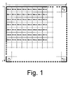
- illustrates a division of a video image into a plurality of blocks of a uniform size for motion estimation and compensation purposes,
- Fig. 2
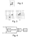
- illustrates a current block B(x,y) and possible spatial prediction positions,
- Fig. 3
- illustrates a current block B(x,y) and possible spatial and temporal prediction positions,
- Fig. 4
- illustrates a configuration of an image rate converter,
- Fig. 5
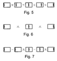
- illustrates different motion phases in a video sequence stemming from a video camera,
- Fig. 6
- illustrates different motion phases of the same moving object of Fig. 5 in a motion picture sequence,
- Fig. 7
- illustrates different motion phases in a video sequence stemming from the motion picture sequence illustrated in Fig. 6 which has been converted in to a video sequence, and
- Fig. 8
- illustrates a configuration of a video encoder including a motion estimator in accordance with the present invention.
- The present invention relates to digital signal processing, especially to signal processing in modern television receivers. Modern television receivers employ up-conversion algorithms in order to increase the reproduced picture quality. For this purpose, intermediate images are to be generated from two subsequent images. For generating an intermediate image, the motion of moving objects has to be taken into account in order to appropriately adapt the object position to the point of time reflected by the interpolated image.
- Motion estimation is performed on a block basis. For this purpose, each received image is divided into a plurality of blocks as illustrated, for example, in Fig. 1. Each current block is individually subjected to motion estimation by determining a best matching block in the previous image.
- In order to avoid a time consuming full search within a predefined search area, only a limited set of candidate vectors is provided to the motion estimator. From these candidate vectors, the motion estimator selects that vector which can predict the current block from the respective block of the previous image with a minimum amount of deviation.
- Fig. 1 illustrates the division of each video image into a plurality of blocks B(x,y). Each block has a width X and a height Y wherein X and Y represent the number of pixels in the line and column direction, respectively. The number of blocks per line or column can be calculated by employing the following formulas:
- For each of these blocks, a motion vector is calculated from a plurality of different candidate vectors. Conventionally, the set of candidate vectors includes for instance the following motion vectors:
u represents the update vector. - As can be seen from the above equations, the candidate vectors may include a zero motion vector (C1), motion vectors of adjacent blocks for a spatial prediction (C2, C3), and/or motion vectors of the previous image for a temporal prediction (C6, C7).
- The spatial prediction is improved by employing update vectors which are accumulated to the spatial prediction vectors C2, C3. In order to take small changes of the object motion compared to a selected candidate vector into account, an update vector is applied to a motion vector to create new candidate vectors C4, C5. Although in the above list of candidate vectors, the update vector
u is only applied to candidate vectors C2 and C3, it may be applied in the same manner to any other candidate vector, for instance to candidate vectors C6, C7. - Although the temporal prediction vectors C6 and C7 of the above list define the use of candidate vectors having an offset of two blocks, any other offset may be employed instead of two, for instance zero, one, three, etc.
- While the temporal prediction vectors have been described with respect to a current and previous image, the term "image" may either relate to fields of an interlaced video sequence or to frames of a progressive video sequence. Correspondingly, the generated intermediate images may be fields or frames depending on the type of video sequence.
- Further, the above list of candidate vectors is neither complete nor requires the inclusion of all of the above mentioned candidate vectors. Any other set of candidate vectors may be employed yielding the determination of a best match motion vector for the current block.
- For each candidate vector, a prediction error is calculated and evaluated in order to determine the best match motion vector. As a measure for the prediction error, the Sum of Absolute Differences (SAD) can be determined. That candidate vector is selected and is considered to represent best the motion of the block which has the smallest SAD.
- As some of the motion vector candidates C1 to C7 may be preferred over other candidate vectors, a programmable "penalty" may be added to the determined SAD for individual candidates. In this manner, the selection of particular candidates can be prioritized. Preferably, the penalty value is proportional to the length of the update vector
u for motion vector candidates C4, C5. - In addition to the above list of candidate vectors, a global motion vector may be further taken into account. A global motion vector represents motion applicable to all blocks of the video image. Such motion vectors appropriately apply to a camera pan.
- The above listed candidate vectors C1 to C7 include previously calculated motion vectors from the spatial neighborhood as illustrated in Fig. 2. These candidate vectors include already processed blocks B(x-1,y) and B(x,y-1) from adjacent positions to the position of the current block B(x,y) as candidate vectors C2 and C3.
- Candidate vectors C6 and C7 represent temporal prediction vectors representing already calculated motion vectors of the previous field n-1. An example for temporal motion prediction vectors is illustrated in Fig. 3 wherein blocks B'(x+2,y) and B'(x,y+2) are marked as prediction vectors.
- The temporal prediction vectors provide a homogenous speed of a moving object if the motion of a scene is nearly constant over a number of fields. Based on the vector information generated by the motion estimation algorithm, an intermediate field is interpolated using motion compensation techniques.
- An example configuration of a known field rate converter is illustrated in Fig. 4. Motion estimation circuit ME calculates a motion vector field and supplies the motion vector field to motion compensated interpolation circuit MCI. The motion compensated output image is displayed on a connected display device.
- Up-conversion algorithms which are used in high end television receivers suffer from poor image quality if the source material is originating from motion pictures. In case of fast motion, border lines of moving objects cannot be reconstructed during interpolation. This is caused by the number of estimation steps required to converge towards a correct motion vector. When employing camera source material, the number of estimation steps required to obtain the correct motion vector is only about half of the number of steps required for motion picture film. This is due to the smaller amount of motion between camera source material images compared to video sequences stemming from motion picture film.
- The different motion phases recorded by either a camera or a film camera and being converted from film camera motion picture data to video camera data are illustrated in Figs. 5, 6 and 7.
- Fig 5 illustrates the motion phases recorded by an electronic camera having an interlaced recording format of a 50 Hz or 60 Hz field rate. In contrast, the same scene recorded by a film camera is illustrated in Fig. 6. Accordingly, motion picture data only reflect less motion phases compared to video data in accordance with television standards like PAL, SECAM or NTSC .
- When converting motion picture data as illustrated in Fig. 6 to a television standard like video format, the motion phases from the motion pictures are repeatedly converted into a plurality of fields. As can be seen from Fig. 7, each motion phase from the motion pictures is transformed into two fields of a sequence of fields in accordance with a two-two pull down conversion.
- When comparing the object positions of the different motion phases represented in the video sequences of Fig. 5 and Fig. 7, a temporal prediction based on the motion phases of Fig. 7 is rather error prone. As only fewer images of the video sequence in Fig. 7 reflect different motion phases, a temporal motion vector prediction has to cope with large shifts of the moving object between the motion phases.
- Motion estimation applied to video sequences cannot accurately take both kinds of image data into account, i.e. video mode data and film mode data. Consequently, the motion vector prediction generally fails for fast moving objects stemming from motion picture. Thus, strong artifacts are visible in a motion compensated sequence of fields for fast moving objects, in particular at the border lines of the moving objects.
- The present invention solves this problem by adapting the prediction motion vector size accordingly. In video mode, the spatial update vectors are set smaller while in film mode, larger update vectors are employed.
- In contrast to prior art approaches applying identical update vectors to video and film mode type image data resulting in motion vector predictions which are not appropriate for both of the modes, the present invention differentiates between the different types of video data resulting in a better adapted motion vector length and direction. In this manner, the accuracy, reliability and efficiency of motion vector determination is improved.
- Generally, spatial motion vector prediction as candidate vectors are defined as follows:
- C4 =
v [(x-1; y),n]+u - C5 =
v [(x; y-1),n]+u - The update vector
u is randomly chosen from a set of update vectors SETupdate. This update vector is modified depending on the detected source mode for the actual search block. In case of a film source, the set of values to be used for the update vectoru has to be larger than for video source data. This is due to larger motion vectors in film source material as can be seen, for instance, from Fig. 5 and Fig. 7. - In accordance with the present invention, the film mode/video mode indication is determined on a block basis. Accordingly, a status signal is assigned to each image block preferably indicating in binary form the current mode, for instance, by "0" for video mode blocks and "1" for blocks stemming from motion picture film.
- In a preferred embodiment, the spatial update vector set (SETupdate) is set to:

- The update vector sets may be assigned as follows:
- For all candidate vectors, the error function, preferably as the sum of absolute differences (SAD), is calculated. According to a further preferred embodiment, the SAD values for motion vector candidates, which are determined by employing update vectors in accordance with the present invention, are modified by adding so-called penalty values. In this manner candidate vectors C4 and C5 may be penalised by adding a value to the SAD value, wherein the added value is proportional to the length of the update vector
u . The motion estimator then selects that candidate vector as the motion vector of the current block having the lowest SAD value from the penalised SAD values. - It is to be noted that a skilled person is aware that the total number of spatial update vectors and the values of the update vectors may be set differently than described above in accordance with the preferred embodiment. Instead of employing a pseudorandom selection of motion vector predictions based on respectively selected two spatial update vectors, the candidate vectors may include more than two candidate vectors which are based on the combination of a previously determined motion vector and different update vectors. Even a number of candidate vectors corresponding to all possible update vectors from the plurality of predetermined update vectors SETupdate may be employed.
- While the present invention has been previously mainly described in the context of interpolation of intermediate images, in particular, for frame-rate conversion in modern television receivers, the improved motion estimation of the present invention may be applied in a corresponding manner to video data compression.
- The compression of video data generally employs a number of main stages. Each individual image is divided into blocks of pixels in order to subject each image to a data compression at a block level. Such a block division may correspond to the division shown in Fig. 1. Spatial redundancies within an image are reduced by applying each block to a transform unit in order to transform the pixels of each block from the spatial domain into the frequency domain. The resulting transform coefficients are quantized, and the quantized transform coefficients are subjected to entropy coding.
- Further, temporal dependencies between blocks of subsequent images are exploited in order to only transmit differences between subsequent images. This is accomplished by employing a motion estimation/compensation technique. The exploiting of temporal dependencies is performed by so-called hybrid coding techniques which combine temporal and spatial compression techniques together with statistical coding.
- Referring to Fig. 8, an example of a hybrid video encoder is illustrated. The video encoder, generally denoted by reference number 1, comprises a subtractor 10 for determining differences between a current video image and a prediction signal of the current image which is based on a motion compensated previously encoded image. A transform and quantization unit 20 transforms the prediction error from the spatial domain into the frequency domain and quantizes the obtained transformed coefficients. An entropy encoding unit 90 entropy encodes the quantized transform coefficients.
- Encoder 1 employs a Differential Pulse Code Modulation (DPCM) which only transmits differences between subsequent images of an input video sequence. These differences are determined by subtractor 10 which receives the video images to be encoded and a prediction signal to be subtracted therefrom.
- The prediction signal is based on the decoding result of previously encoded images on the encoder site. This is accomplished by a decoding unit incorporated into the video encoder. The decoding unit performs the encoding steps in reverse manner. Inverse quantization and inverse transform unit 30 dequantizes the quantized coefficients and applies an inverse transform to the dequantized coefficients. Adder 35 accumulates the decoded differences and the prediction signal.
- The prediction signal results from an estimation of motion between current and previous fields or frames. The motion estimation is performed by a motion estimator 70 receiving the current input signal and the locally decoded images. Motion estimation is preferably performed in accordance with the present invention. Based on the results of motion estimation, motion compensation is performed by motion compensator 60.
- Summarizing, the present invention provides an improved method for motion estimation and in particular for a motion compensated interpolation. By taking the source of the video data into account, the size of update vectors to be employed for determining spatial prediction vectors is set in accordance with the detected source mode. By selecting an appropriate update vector size, the accuracy of the predicted motion and consequently, the picture quality of motion compensated interpolated images can be increased considerably.
Claims (32)
- A method for determining a motion vector for a block of a current image in a sequence of video images, each video image being divided into a plurality of blocks, the method determining a motion vector for a current block by combing a previously determined motion vector and a predetermined update vector (
u )
characterized by
setting the size of said update vector (u ) depending on whether or not the image data of said current block stem from a motion picture type image. - A method according to claim 1, wherein a determination that image data stem from a motion picture type image is based on the detection of a motion picture to video data conversion pattern in the sequence of video images.
- A method according to claim 2, wherein said conversion pattern being a 2:2 or 3:2 conversion pattern.
- A method according to any of claims 1 to 3, wherein a determination that image data stem from a motion picture type image is determined on an image basis, in particular per field or frame.
- A method according to any of claims 1 to 3, wherein a determination that image data stem from a motion picture type image is determined on a block basis.
- A method according to any of claims 1 to 5, wherein the size of said update vector is set larger if said image data stem from motion picture.
- A method according to claim 6, wherein in case of motion picture image data the size of said update vector (
u ) being set between 1.5 and 2.5 as large, preferably twice as large, compared to the size of an update vector for no motion picture type image data. - A method according to any of claims 1 to 7, wherein said update vector (
u ) being selected from a plurality of predetermined update vectors (u ). - A method according to any of claims 1 to 8, further comprising the steps of:selecting a motion vector for said current block from a plurality of candidate motion vectors (C1-C7) including said motion vector estimated by combing a previously determined motion vector and a predetermined update vector (
u ), andassigning said selected motion vector to said current block. - A method according to claim 9, wherein said selecting step comprising the steps of:calculating an error value for each of the candidate motion vectors (C1-C7), andselecting that motion vector having the smallest error value.
- A method according to any of claims 1 to 10, wherein said candidate vectors include a plurality of combinations of a given previously determined motion vector with different update vectors (
u ) from a plurality of predetermined update vectors. - A method according to any of claims 1 to 11, wherein said previously determined motion vector include at least one of the following motion vectors:a zero motion vector pointing to the identical block position of the current block,a motion vector determined for an adjacent block in the current image, anda motion vector determined for a block in a previous image.
- A method according to any of claims 9 to 12, wherein said candidate vectors (C1-C7) further include at least one of the following motion vectors:a zero motion vector (C1) pointing to the identical block position of the current block,a motion vector (C2, C3) determined for an adjacent block in the current image, anda motion vector (C6, C7) determined for a block in a previous image.
- A method for encoding a sequence of video images including motion compensation employing a motion estimation method in accordance with any of claims 1 to 13.
- A method for interpolating a sequence of video images including motion compensation employing a motion estimation method in accordance with any of claims 1 to 13.
- A method for converting a field- or frame-rate of a video sequence by employing motion compensation in accordance with claim 15.
- A motion estimator for determining a motion vector for a block of a current image in a sequence of video images, each video image being divided into a plurality of blocks, the motion estimator determining a motion vector for a current block by combing a previously determined motion vector and a predetermined update vector (
u )
characterized by
a film mode detector determining whether or not the image data of said current block stem from a motion picture type image, and
adjusting means for setting the size of said update vectoru ) depending on whether or not the image data of said current block stem from a motion picture type image. - A motion estimator according to claim 17, wherein said film mode detector determining that image data stem from a motion picture type image based on the detection of a motion picture to video data conversion pattern in the sequence of video images.
- A motion estimator according to claim 18, wherein said conversion pattern being a 2:2 or 3:2 conversion pattern.
- A motion estimator according to any of claims 17 to 19, wherein said film mode detector determining that image data stem from a motion picture type image on an image basis, in particular per field or frame.
- A motion estimator according to any of claims 17 to 19, wherein film mode detector determining that image data stem from a motion picture type image on a block basis.
- A motion estimator according to any of claims 17 to 21, wherein said adjusting means setting the size of said update vector larger if said image data stem from motion picture.
- A motion estimator according to claim 22, wherein said adjusting means setting in case of motion picture image data the size of said update vector (
u ) being between 1.5 and 2.5 as large, preferably twice as large, compared to the size of an update vector for no motion picture type image data. - A motion estimator according to any of claims 17 to 23, wherein said adjusting means comprising a memory and selecting said update vector (
u ) from a plurality of prestored update vectors (u ). - A motion estimator according to any of claims 17 to 24, further comprising a selector for selecting a motion vector for said current block from a plurality of candidate motion vectors (C1-C7) including said motion vector estimated by combining a previously determined motion vector and a predetermined update vector (
u ). - A motion estimator according to claim 25, wherein said selector comprising:a processing unit for calculating an error value for each of the candidate motion vectors (C1-C7), anda comparator for selecting that motion vector having the smallest error value.
- A motion estimator according to any of claims 17 to 26, wherein said candidate vectors include a plurality of combinations of a given previously determined motion vector with different update vectors (
u ) from a plurality of predetermined update vectors. - A motion estimator according to any of claims 17 to 27, wherein said previously determined motion vector include at least one of the following motion vectors:a zero motion vector pointing to the identical block position of the current block,a motion vector determined for an adjacent block in the current image, anda motion vector determined for a block in a previous image.
- A motion estimator according to any of claims 25 to 28, wherein said candidate vectors (C1-C7) further include at least one of the following motion vectors:a zero motion vector (C1) pointing to the identical block position of the current block,a motion vector (C2, C3) determined for an adjacent block in the current image, anda motion vector (C6, C7) determined for a block in a previous image.
- An encoder for encoding a sequence of video images including motion compensation employing a motion estimator in accordance with any of claims 17 to 29.
- An interpolator for interpolating a sequence of video images including motion compensation employing a motion estimator in accordance with any of claims 17 to 29.
- A converter for converting a field- or frame-rate of a video sequence by employing motion compensation in accordance with claim 31.
Priority Applications (6)
| Application Number | Priority Date | Filing Date | Title |
|---|---|---|---|
| DE602004030993T DE602004030993D1 (en) | 2004-04-30 | 2004-04-30 | Motion estimation using adaptive spatial refinement vectors |
| EP04010296A EP1592258B1 (en) | 2004-04-30 | 2004-04-30 | Motion estimation employing adaptive spatial update vectors |
| US11/067,649 US7920627B2 (en) | 2004-04-30 | 2005-02-28 | Motion estimation employing adaptive spatial update vectors |
| JP2005112360A JP4528662B2 (en) | 2004-04-30 | 2005-04-08 | Motion detection using adaptive space latest vector |
| CN2005100674700A CN1694501B (en) | 2004-04-30 | 2005-04-25 | Motion estimation employing adaptive spatial update vectors |
| KR1020050035494A KR20060047581A (en) | 2004-04-30 | 2005-04-28 | Motion estimation employing adaptive spatial update vectors |
Applications Claiming Priority (1)
| Application Number | Priority Date | Filing Date | Title |
|---|---|---|---|
| EP04010296A EP1592258B1 (en) | 2004-04-30 | 2004-04-30 | Motion estimation employing adaptive spatial update vectors |
Publications (2)
| Publication Number | Publication Date |
|---|---|
| EP1592258A1 true EP1592258A1 (en) | 2005-11-02 |
| EP1592258B1 EP1592258B1 (en) | 2011-01-12 |
Family
ID=34924800
Family Applications (1)
| Application Number | Title | Priority Date | Filing Date |
|---|---|---|---|
| EP04010296A Expired - Fee Related EP1592258B1 (en) | 2004-04-30 | 2004-04-30 | Motion estimation employing adaptive spatial update vectors |
Country Status (6)
| Country | Link |
|---|---|
| US (1) | US7920627B2 (en) |
| EP (1) | EP1592258B1 (en) |
| JP (1) | JP4528662B2 (en) |
| KR (1) | KR20060047581A (en) |
| CN (1) | CN1694501B (en) |
| DE (1) | DE602004030993D1 (en) |
Cited By (5)
| Publication number | Priority date | Publication date | Assignee | Title |
|---|---|---|---|---|
| WO2008035472A1 (en) | 2006-09-20 | 2008-03-27 | Sharp Kabushiki Kaisha | Image displaying device and method, and image processing device and method |
| EP2066124A1 (en) * | 2006-09-20 | 2009-06-03 | Sharp Kabushiki Kaisha | Image display device and method and image processing device and method |
| GB2487197A (en) * | 2011-01-11 | 2012-07-18 | Canon Kk | Video encoding and decoding |
| US9167132B2 (en) | 2007-10-12 | 2015-10-20 | Samsung Electronics Co., Ltd. | System and method of estimating motion of image using block sampling |
| US10075707B2 (en) | 2011-03-09 | 2018-09-11 | Canon Kabushiki Kaisha | Video encoding and decoding |
Families Citing this family (26)
| Publication number | Priority date | Publication date | Assignee | Title |
|---|---|---|---|---|
| DE602004002455T2 (en) * | 2004-04-30 | 2007-01-11 | Matsushita Electric Industrial Co., Ltd., Kadoma | Motion vector estimation through adaptive temporal prediction |
| GB2432068B (en) * | 2005-11-02 | 2010-10-06 | Imagination Tech Ltd | Motion estimation |
| JP4843367B2 (en) * | 2006-04-28 | 2011-12-21 | 株式会社東芝 | Y / C separation circuit |
| US8340185B2 (en) * | 2006-06-27 | 2012-12-25 | Marvell World Trade Ltd. | Systems and methods for a motion compensated picture rate converter |
| US8249371B2 (en) | 2007-02-23 | 2012-08-21 | International Business Machines Corporation | Selective predictor and selective predictive encoding for two-dimensional geometry compression |
| US20080304568A1 (en) * | 2007-06-11 | 2008-12-11 | Himax Technologies Limited | Method for motion-compensated frame rate up-conversion |
| US9641861B2 (en) * | 2008-01-25 | 2017-05-02 | Mediatek Inc. | Method and integrated circuit for video processing |
| JP4883029B2 (en) * | 2008-03-05 | 2012-02-22 | パナソニック株式会社 | Motion vector detection circuit, motion vector detection device, and integrated circuit |
| US20090225227A1 (en) * | 2008-03-05 | 2009-09-10 | Panasonic Corporation | Motion vector detecting device |
| WO2009119347A1 (en) | 2008-03-28 | 2009-10-01 | 日本電気株式会社 | Image processing system, image processing method, and recording medium containing an image processing program |
| KR101377660B1 (en) * | 2008-09-30 | 2014-03-26 | 에스케이텔레콤 주식회사 | Motion Vector Encoding/Decoding Method and Apparatus Using Multiple Motion Vector Estimation and Video Encoding/Decoding Method and Apparatus Using Same |
| GB2469679B (en) * | 2009-04-23 | 2012-05-02 | Imagination Tech Ltd | Object tracking using momentum and acceleration vectors in a motion estimation system |
| JP2010288098A (en) * | 2009-06-12 | 2010-12-24 | Sony Corp | Device, method and program for interpolation of image frame |
| US20110001882A1 (en) * | 2009-07-06 | 2011-01-06 | Sony Corporation | Method and system for determining motion vectors for flat regions |
| US8446524B2 (en) * | 2010-06-21 | 2013-05-21 | Realtek Semiconductor Corp. | Apparatus and method for frame rate conversion |
| WO2012140821A1 (en) | 2011-04-12 | 2012-10-18 | パナソニック株式会社 | Motion-video encoding method, motion-video encoding apparatus, motion-video decoding method, motion-video decoding apparatus, and motion-video encoding/decoding apparatus |
| US9485518B2 (en) | 2011-05-27 | 2016-11-01 | Sun Patent Trust | Decoding method and apparatus with candidate motion vectors |
| EP3614665B1 (en) | 2011-05-27 | 2022-03-23 | Sun Patent Trust | Apparatus, method and program for decoding moving pictures |
| TW201304552A (en) | 2011-05-31 | 2013-01-16 | Panasonic Corp | Moving picture coding method, moving picture coding apparatus, moving picture decoding method, moving picture decoding apparatus, and moving picture coding and decoding apparatus |
| CN106851269B (en) | 2011-06-30 | 2019-11-15 | 太阳专利托管公司 | Picture decoding method and device, image encoding method and device, coding and decoding device |
| IN2014CN00729A (en) | 2011-08-03 | 2015-04-03 | Panasonic Corp | |
| GB201113527D0 (en) | 2011-08-04 | 2011-09-21 | Imagination Tech Ltd | External vectors in a motion estimation system |
| CN108881903B (en) | 2011-10-19 | 2022-01-04 | 太阳专利托管公司 | Image encoding method and device, image decoding method and device, and encoding and decoding device |
| TW201345262A (en) * | 2012-04-20 | 2013-11-01 | Novatek Microelectronics Corp | Image processing circuit and image processing method |
| CN103379303A (en) * | 2012-04-25 | 2013-10-30 | 联咏科技股份有限公司 | Image processing circuit and image processing method |
| US20150110190A1 (en) * | 2013-10-21 | 2015-04-23 | Sony Corporation | Method and apparatus for motion estimation |
Citations (2)
| Publication number | Priority date | Publication date | Assignee | Title |
|---|---|---|---|---|
| EP0578290A1 (en) * | 1992-05-06 | 1994-01-12 | Koninklijke Philips Electronics N.V. | Motion estimation |
| WO1999016248A1 (en) * | 1997-09-23 | 1999-04-01 | Koninklijke Philips Electronics N.V. | Motion estimation and motion-compensated interpolation |
Family Cites Families (9)
| Publication number | Priority date | Publication date | Assignee | Title |
|---|---|---|---|---|
| US5317398A (en) * | 1992-08-17 | 1994-05-31 | Rca Thomson Licensing Corporation | Video/film-mode (3:2 pulldown) detector using patterns of two-field differences |
| JPH1013836A (en) * | 1996-06-21 | 1998-01-16 | Canon Inc | Motion vector detector |
| EP0874523B1 (en) * | 1997-04-24 | 2004-03-03 | STMicroelectronics S.r.l. | Method for motion-estimated and compensated field rate up-conversion (FRU) for video applications, and device for actuating such a method |
| KR100582856B1 (en) | 1997-09-23 | 2006-05-24 | 코닌클리케 필립스 일렉트로닉스 엔.브이. | Motion estimation and motion-compensated interpolation |
| CN1456015A (en) * | 2001-01-11 | 2003-11-12 | 皇家菲利浦电子有限公司 | Recognizing film and video objects occuring in parallel in single television signal fields |
| KR100857731B1 (en) * | 2001-02-21 | 2008-09-10 | 코닌클리케 필립스 일렉트로닉스 엔.브이. | Facilitating motion estimation |
| JP2004023673A (en) * | 2002-06-19 | 2004-01-22 | Sony Corp | Motion vector detecting apparatus and method therefor movement compensation and method therefor |
| KR100854091B1 (en) * | 2002-07-13 | 2008-08-25 | 삼성전자주식회사 | Apparatus for detecting a film-mode of the being inputted image signal |
| US7480334B2 (en) * | 2003-12-23 | 2009-01-20 | Genesis Microchip Inc. | Temporal motion vector filtering |
-
2004
- 2004-04-30 DE DE602004030993T patent/DE602004030993D1/en not_active Expired - Lifetime
- 2004-04-30 EP EP04010296A patent/EP1592258B1/en not_active Expired - Fee Related
-
2005
- 2005-02-28 US US11/067,649 patent/US7920627B2/en not_active Expired - Fee Related
- 2005-04-08 JP JP2005112360A patent/JP4528662B2/en not_active Expired - Fee Related
- 2005-04-25 CN CN2005100674700A patent/CN1694501B/en not_active Expired - Fee Related
- 2005-04-28 KR KR1020050035494A patent/KR20060047581A/en not_active Application Discontinuation
Patent Citations (2)
| Publication number | Priority date | Publication date | Assignee | Title |
|---|---|---|---|---|
| EP0578290A1 (en) * | 1992-05-06 | 1994-01-12 | Koninklijke Philips Electronics N.V. | Motion estimation |
| WO1999016248A1 (en) * | 1997-09-23 | 1999-04-01 | Koninklijke Philips Electronics N.V. | Motion estimation and motion-compensated interpolation |
Non-Patent Citations (2)
| Title |
|---|
| HAAN DE G ET AL: "AN EFFICIENT TRUE-MOTION ESTIMATOR USING CANDIDATE VECTORS FROM A PARAMETRIC MOTION MODEL", IEEE TRANSACTIONS ON CIRCUITS AND SYSTEMS FOR VIDEO TECHNOLOGY, IEEE INC. NEW YORK, US, vol. 8, no. 1, 1 February 1998 (1998-02-01), pages 85 - 91, XP000737028, ISSN: 1051-8215 * |
| OGURA E ET AL: "A 1.2-W SINGLE-CHIP MPEG2 MP ML VIDEO ENCODER LSI INCLUDING WIDE SEARCH RANGE (H:+/-288, V:+/-96) MOTION ESTIMATION AND 81-MOPS CONTROLLER", IEEE JOURNAL OF SOLID-STATE CIRCUITS, IEEE INC. NEW YORK, US, vol. 33, no. 11, November 1998 (1998-11-01), pages 1765 - 1771, XP000875470, ISSN: 0018-9200 * |
Cited By (16)
| Publication number | Priority date | Publication date | Assignee | Title |
|---|---|---|---|---|
| EP2538669A1 (en) * | 2006-09-20 | 2012-12-26 | Sharp Kabushiki Kaisha | Image displaying device and method, and image processing device and method |
| US8780267B2 (en) | 2006-09-20 | 2014-07-15 | Sharp Kabushiki Kaisha | Image displaying device and method and image processing device and method determining content genre for preventing image deterioration |
| EP2066124A1 (en) * | 2006-09-20 | 2009-06-03 | Sharp Kabushiki Kaisha | Image display device and method and image processing device and method |
| CN101518066A (en) * | 2006-09-20 | 2009-08-26 | 夏普株式会社 | Image displaying device and method, and image processing device and method |
| WO2008035472A1 (en) | 2006-09-20 | 2008-03-27 | Sharp Kabushiki Kaisha | Image displaying device and method, and image processing device and method |
| EP2066122A4 (en) * | 2006-09-20 | 2012-04-11 | Sharp Kk | Image displaying device and method, and image processing device and method |
| EP2066122A1 (en) * | 2006-09-20 | 2009-06-03 | Sharp Kabushiki Kaisha | Image displaying device and method, and image processing device and method |
| CN101518066B (en) * | 2006-09-20 | 2015-07-08 | 夏普株式会社 | Image displaying device and method, and image processing device and method |
| EP2066124A4 (en) * | 2006-09-20 | 2010-12-22 | Sharp Kk | Image display device and method and image processing device and method |
| EP2487900A3 (en) * | 2006-09-20 | 2013-05-15 | Sharp Kabushiki Kaisha | Image displaying device and method, and image processing device and method |
| US8325272B2 (en) | 2006-09-20 | 2012-12-04 | Sharp Kabushiki Kaisha | Image displaying device and method and image processing device and method for preventing image deterioration due to motion-compensated rate conversion processing |
| US9167132B2 (en) | 2007-10-12 | 2015-10-20 | Samsung Electronics Co., Ltd. | System and method of estimating motion of image using block sampling |
| GB2487197B (en) * | 2011-01-11 | 2015-06-17 | Canon Kk | Video encoding and decoding with improved error resilience |
| GB2487197A (en) * | 2011-01-11 | 2012-07-18 | Canon Kk | Video encoding and decoding |
| US9648341B2 (en) | 2011-01-11 | 2017-05-09 | Canon Kabushiki Kaisha | Video encoding and decoding with improved error resilience |
| US10075707B2 (en) | 2011-03-09 | 2018-09-11 | Canon Kabushiki Kaisha | Video encoding and decoding |
Also Published As
| Publication number | Publication date |
|---|---|
| JP2005318576A (en) | 2005-11-10 |
| JP4528662B2 (en) | 2010-08-18 |
| CN1694499A (en) | 2005-11-09 |
| US20050243927A1 (en) | 2005-11-03 |
| CN1694501B (en) | 2010-12-15 |
| DE602004030993D1 (en) | 2011-02-24 |
| US7920627B2 (en) | 2011-04-05 |
| EP1592258B1 (en) | 2011-01-12 |
| KR20060047581A (en) | 2006-05-18 |
Similar Documents
| Publication | Publication Date | Title |
|---|---|---|
| US7920627B2 (en) | Motion estimation employing adaptive spatial update vectors | |
| EP1592248B1 (en) | Motion vector estimation employing adaptive temporal prediction | |
| US7852937B2 (en) | Motion vector estimation employing line and column vectors | |
| US7693218B2 (en) | Motion vector estimation with improved motion vector selection | |
| US7801215B2 (en) | Motion estimation technique for digital video encoding applications | |
| US5587741A (en) | Apparatus and method for detecting motion vectors to half-pixel accuracy | |
| JPH07162869A (en) | Moving image encoder | |
| US8073054B2 (en) | Unit for and method of estimating a current motion vector | |
| EP0577418B1 (en) | Apparatus for motion compensation coding of digital video signal | |
| EP1198139A1 (en) | Method and apparatus for encoding video fields | |
| Biswas et al. | A novel de-interlacing technique based on phase plane correlation motion estimation | |
| KR0152014B1 (en) | Method and apparauts for moving estimation in image data compression | |
| US7013048B2 (en) | Method and apparatus for coding a digitized original picture and method and apparatus for decoding a digitized coded picture | |
| JP3237029B2 (en) | Video compression device | |
| EP0950899A1 (en) | Method for estimating the noise level in a video sequence | |
| JP2001245300A (en) | Prediction vector generating system and image coder | |
| JPH07170524A (en) | Movement vector detector | |
| KR20070029109A (en) | Video encoding method and device |
Legal Events
| Date | Code | Title | Description |
|---|---|---|---|
| PUAI | Public reference made under article 153(3) epc to a published international application that has entered the european phase |
Free format text: ORIGINAL CODE: 0009012 |
|
| 17P | Request for examination filed |
Effective date: 20050121 |
|
| AK | Designated contracting states |
Kind code of ref document: A1 Designated state(s): AT BE BG CH CY CZ DE DK EE ES FI FR GB GR HU IE IT LI LU MC NL PL PT RO SE SI SK TR |
|
| AX | Request for extension of the european patent |
Extension state: AL HR LT LV MK |
|
| AKX | Designation fees paid |
Designated state(s): DE FR GB |
|
| RAP1 | Party data changed (applicant data changed or rights of an application transferred) |
Owner name: PANASONIC CORPORATION |
|
| GRAP | Despatch of communication of intention to grant a patent |
Free format text: ORIGINAL CODE: EPIDOSNIGR1 |
|
| GRAS | Grant fee paid |
Free format text: ORIGINAL CODE: EPIDOSNIGR3 |
|
| GRAA | (expected) grant |
Free format text: ORIGINAL CODE: 0009210 |
|
| AK | Designated contracting states |
Kind code of ref document: B1 Designated state(s): DE FR GB |
|
| REG | Reference to a national code |
Ref country code: GB Ref legal event code: FG4D |
|
| REF | Corresponds to: |
Ref document number: 602004030993 Country of ref document: DE Date of ref document: 20110224 Kind code of ref document: P |
|
| REG | Reference to a national code |
Ref country code: DE Ref legal event code: R096 Ref document number: 602004030993 Country of ref document: DE Effective date: 20110224 |
|
| PLBE | No opposition filed within time limit |
Free format text: ORIGINAL CODE: 0009261 |
|
| STAA | Information on the status of an ep patent application or granted ep patent |
Free format text: STATUS: NO OPPOSITION FILED WITHIN TIME LIMIT |
|
| 26N | No opposition filed |
Effective date: 20111013 |
|
| REG | Reference to a national code |
Ref country code: DE Ref legal event code: R097 Ref document number: 602004030993 Country of ref document: DE Effective date: 20111013 |
|
| PGFP | Annual fee paid to national office [announced via postgrant information from national office to epo] |
Ref country code: DE Payment date: 20120502 Year of fee payment: 9 |
|
| PGFP | Annual fee paid to national office [announced via postgrant information from national office to epo] |
Ref country code: FR Payment date: 20120504 Year of fee payment: 9 Ref country code: GB Payment date: 20120425 Year of fee payment: 9 |
|
| GBPC | Gb: european patent ceased through non-payment of renewal fee |
Effective date: 20130430 |
|
| PG25 | Lapsed in a contracting state [announced via postgrant information from national office to epo] |
Ref country code: GB Free format text: LAPSE BECAUSE OF NON-PAYMENT OF DUE FEES Effective date: 20130430 Ref country code: DE Free format text: LAPSE BECAUSE OF NON-PAYMENT OF DUE FEES Effective date: 20131101 |
|
| REG | Reference to a national code |
Ref country code: FR Ref legal event code: ST Effective date: 20131231 |
|
| REG | Reference to a national code |
Ref country code: DE Ref legal event code: R119 Ref document number: 602004030993 Country of ref document: DE Effective date: 20131101 |
|
| PG25 | Lapsed in a contracting state [announced via postgrant information from national office to epo] |
Ref country code: FR Free format text: LAPSE BECAUSE OF NON-PAYMENT OF DUE FEES Effective date: 20130430 |