EP1592221A2 - Peripherals of computer - Google Patents
Peripherals of computer Download PDFInfo
- Publication number
- EP1592221A2 EP1592221A2 EP05103466A EP05103466A EP1592221A2 EP 1592221 A2 EP1592221 A2 EP 1592221A2 EP 05103466 A EP05103466 A EP 05103466A EP 05103466 A EP05103466 A EP 05103466A EP 1592221 A2 EP1592221 A2 EP 1592221A2
- Authority
- EP
- European Patent Office
- Prior art keywords
- peripheral
- function information
- descriptor
- usb
- scanner
- Prior art date
- Legal status (The legal status is an assumption and is not a legal conclusion. Google has not performed a legal analysis and makes no representation as to the accuracy of the status listed.)
- Granted
Links
- 230000002093 peripheral effect Effects 0.000 title claims abstract description 135
- 230000006870 function Effects 0.000 claims abstract description 298
- 238000004891 communication Methods 0.000 claims abstract description 40
- 230000001419 dependent effect Effects 0.000 claims abstract description 38
- 238000001514 detection method Methods 0.000 claims description 44
- 238000000034 method Methods 0.000 claims description 15
- 239000000284 extract Substances 0.000 claims description 6
- 238000012546 transfer Methods 0.000 description 26
- 238000010276 construction Methods 0.000 description 17
- 238000010586 diagram Methods 0.000 description 15
- 230000000994 depressogenic effect Effects 0.000 description 5
- 230000004913 activation Effects 0.000 description 4
- 238000003825 pressing Methods 0.000 description 3
- 238000012545 processing Methods 0.000 description 3
- 230000005540 biological transmission Effects 0.000 description 2
- 230000005055 memory storage Effects 0.000 description 2
- 241000110058 Candidatus Phytoplasma pini Species 0.000 description 1
- 238000004519 manufacturing process Methods 0.000 description 1
- 238000012986 modification Methods 0.000 description 1
- 230000004048 modification Effects 0.000 description 1
Images










Classifications
-
- H—ELECTRICITY
- H04—ELECTRIC COMMUNICATION TECHNIQUE
- H04N—PICTORIAL COMMUNICATION, e.g. TELEVISION
- H04N1/00—Scanning, transmission or reproduction of documents or the like, e.g. facsimile transmission; Details thereof
- H04N1/00127—Connection or combination of a still picture apparatus with another apparatus, e.g. for storage, processing or transmission of still picture signals or of information associated with a still picture
- H04N1/00204—Connection or combination of a still picture apparatus with another apparatus, e.g. for storage, processing or transmission of still picture signals or of information associated with a still picture with a digital computer or a digital computer system, e.g. an internet server
- H04N1/00236—Connection or combination of a still picture apparatus with another apparatus, e.g. for storage, processing or transmission of still picture signals or of information associated with a still picture with a digital computer or a digital computer system, e.g. an internet server using an image reading or reproducing device, e.g. a facsimile reader or printer, as a local input to or local output from a computer
-
- H—ELECTRICITY
- H04—ELECTRIC COMMUNICATION TECHNIQUE
- H04N—PICTORIAL COMMUNICATION, e.g. TELEVISION
- H04N1/00—Scanning, transmission or reproduction of documents or the like, e.g. facsimile transmission; Details thereof
- H04N1/00127—Connection or combination of a still picture apparatus with another apparatus, e.g. for storage, processing or transmission of still picture signals or of information associated with a still picture
- H04N1/00204—Connection or combination of a still picture apparatus with another apparatus, e.g. for storage, processing or transmission of still picture signals or of information associated with a still picture with a digital computer or a digital computer system, e.g. an internet server
- H04N1/00236—Connection or combination of a still picture apparatus with another apparatus, e.g. for storage, processing or transmission of still picture signals or of information associated with a still picture with a digital computer or a digital computer system, e.g. an internet server using an image reading or reproducing device, e.g. a facsimile reader or printer, as a local input to or local output from a computer
- H04N1/00241—Connection or combination of a still picture apparatus with another apparatus, e.g. for storage, processing or transmission of still picture signals or of information associated with a still picture with a digital computer or a digital computer system, e.g. an internet server using an image reading or reproducing device, e.g. a facsimile reader or printer, as a local input to or local output from a computer using an image reading device as a local input to a computer
-
- H—ELECTRICITY
- H04—ELECTRIC COMMUNICATION TECHNIQUE
- H04N—PICTORIAL COMMUNICATION, e.g. TELEVISION
- H04N1/00—Scanning, transmission or reproduction of documents or the like, e.g. facsimile transmission; Details thereof
- H04N1/00127—Connection or combination of a still picture apparatus with another apparatus, e.g. for storage, processing or transmission of still picture signals or of information associated with a still picture
- H04N1/00278—Connection or combination of a still picture apparatus with another apparatus, e.g. for storage, processing or transmission of still picture signals or of information associated with a still picture with a printing apparatus, e.g. a laser beam printer
-
- H—ELECTRICITY
- H04—ELECTRIC COMMUNICATION TECHNIQUE
- H04N—PICTORIAL COMMUNICATION, e.g. TELEVISION
- H04N2201/00—Indexing scheme relating to scanning, transmission or reproduction of documents or the like, and to details thereof
- H04N2201/0008—Connection or combination of a still picture apparatus with another apparatus
- H04N2201/0034—Details of the connection, e.g. connector, interface
- H04N2201/0044—Connecting to a plurality of different apparatus; Using a plurality of different connectors
-
- H—ELECTRICITY
- H04—ELECTRIC COMMUNICATION TECHNIQUE
- H04N—PICTORIAL COMMUNICATION, e.g. TELEVISION
- H04N2201/00—Indexing scheme relating to scanning, transmission or reproduction of documents or the like, and to details thereof
- H04N2201/0008—Connection or combination of a still picture apparatus with another apparatus
- H04N2201/0034—Details of the connection, e.g. connector, interface
- H04N2201/0048—Type of connection
- H04N2201/0049—By wire, cable or the like
-
- H—ELECTRICITY
- H04—ELECTRIC COMMUNICATION TECHNIQUE
- H04N—PICTORIAL COMMUNICATION, e.g. TELEVISION
- H04N2201/00—Indexing scheme relating to scanning, transmission or reproduction of documents or the like, and to details thereof
- H04N2201/0077—Types of the still picture apparatus
- H04N2201/0081—Image reader
Definitions
- the invention relates to peripherals which are connected to an upper apparatus through a USB (Universal Serial Bus) interface and, more particularly, to peripherals for realizing multi-function.
- USB Universal Serial Bus
- An upper apparatus (hereinafter, referred to as a PC (personal computer)) having a USB-connecting function can be connected and disconnected to/from peripherals in the state where the PC operates (state where a power source is ON) and, further, can be connected in parallel to a plurality of peripherals. Therefore, since the USB-connection is easily detachable and a system can be relatively freely constructed, the USB-connection has been widespread.
- the peripheral added by the USB-connection is recognized by the PC at the moment when it is physically connected to the PC.
- the PC which recognized the peripheral searches for a driver of the recognized peripheral from drivers which it already has and makes device definition by the searched driver in order to control the peripheral.
- a connection control function of the peripheral mentioned above an inserting/removing function of the peripherals called a "plug & play (PinP) function" has been known.
- the plug & play function is realized as will be explained hereinbelow.
- the PC recognizes the USB-connected peripheral (device), automatically searches for a necessary device driver, and activates the corresponding driver, thereby enabling the added peripheral to be used.
- the PC detects the USB-connection of the peripheral, a bus for USB-connecting the PC and the peripheral is reset, and after the bus resetting, the PC and the peripheral start communication called a "control transfer".
- the peripheral In the control transfer, the peripheral notifies the PC of information called a device descriptor necessary for the device definition. Function information indicative of functions of the peripheral is shown in the device descriptor.
- the PC specifies the peripheral as a communication partner destination on the basis of the function information indicative of the functions of the peripheral shown in the device descriptor, makes the device definition for allocating an address called an "end point" to the specified peripheral, and starts USB-communication with the peripheral.
- Multi-function peripherals (hereinbelow, referred to as MFP) having a plurality of functions such as scanner function, printer function, facsimile (FAX) function, and the like have been widespread as peripherals. Also in the case of USB-connecting the MFP to the PC and making USB-communication, the PC is notified of the device descriptor showing the plurality of functions provided for the MFP by the control transfer.
- MFP Multi-function peripherals
- FAX facsimile
- the PC which received the notification issues a switching command of a connecting construction (vendor request) called a "configuration" and makes the device definition.
- a connecting construction vendor request
- the dedicated driver for selecting the desired function from the plurality of functions and issuing the switching command of the connecting construction is needed and it is necessary to develop such a dedicated driver and install it into the PC as mentioned above, they cause a problem.
- a peripheral for notifying a USB-connected upper apparatus of a device descriptor and allowing the upper apparatus to specify a communication partner destination on the basis of function information shown in the device descriptor comprising:
- the peripheral may be an image reading apparatus and the dependent peripheral may be an image forming apparatus.
- the peripheral function information holding unit holds the function information indicative of an image reading function
- the dependent peripheral function information holding unit holds the function information indicative of an image forming function.
- the peripheral function information holding unit holds the function information indicative of an image forming function
- the dependent peripheral function information holding unit holds the function information indicative of an image reading function
- the peripheral further comprises an operation panel which receives the selecting instruction, and wherein when the selecting instruction is received by the operation panel, the USB control unit executes bus resetting in the USB-connection with the upper apparatus before the notification of the device descriptor.
- the USB control unit has a multi-device descriptor forming unit which forms the device descriptor in which the function information which is read out based on the selecting instruction is contained.
- the peripheral may further comprise an original reading unit which reads an original, and wherein when it is detected that the original has been arranged, the original reading unit notifies the USB control unit of an original detection signal as the selecting instruction, and when the original detection signal is received, the USB control unit reads out the function information indicative of the image reading function.
- the peripheral may further comprise a timer which notifies the USB control unit of a left-original detection signal as the selecting instruction when it is detected that the original has been arranged and left, and wherein when the left-original detection signal is received, the USB control unit reads out the function information indicative of the image forming function.
- the original reading unit reads out the arranged original and, when it is detected that there are no originals to be read, notifies the USB control unit of an end detection signal as the selecting instruction, and when the end detection signal is received, the USB control unit reads out the function information indicative of the image forming function.
- the peripheral may further comprise a specific information extracting unit which analyzes a control command from the upper apparatus and extracts specific information, and wherein when an instruction to execute bus resetting in the USB-connection with the upper apparatus is shown in the extracted specific information, the USB control unit executes the bus resetting.
- a specific information extracting unit which analyzes a control command from the upper apparatus and extracts specific information, and wherein when an instruction to execute bus resetting in the USB-connection with the upper apparatus is shown in the extracted specific information, the USB control unit executes the bus resetting.
- the peripheral may further comprise a specific information extracting unit which analyzes a control command from the upper apparatus and extracts specific information, and wherein when the specific information is a command described by a control language of an image reading apparatus, the specific information extracting unit notifies the USB control unit of the command as the selecting instruction, and when the command is received, the USB control unit reads out the function information indicative of the image reading function.
- a specific information extracting unit which analyzes a control command from the upper apparatus and extracts specific information, and wherein when the specific information is a command described by a control language of an image reading apparatus, the specific information extracting unit notifies the USB control unit of the command as the selecting instruction, and when the command is received, the USB control unit reads out the function information indicative of the image reading function.
- the peripheral may further comprise a specific information extracting unit which analyzes a control command from the upper apparatus and extracts specific information, and wherein when the specific information is a command described by a control language of an image forming apparatus, the specific information extracting unit notifies the USB control unit of the command as the selecting instruction, and when the command is received, the USB control unit reads out the function information indicative of the image forming function.
- a specific information extracting unit which analyzes a control command from the upper apparatus and extracts specific information, and wherein when the specific information is a command described by a control language of an image forming apparatus, the specific information extracting unit notifies the USB control unit of the command as the selecting instruction, and when the command is received, the USB control unit reads out the function information indicative of the image forming function.
- the USB control unit when information showing that a process based on the command has been finished is received as the selecting instruction, on the basis of the command, the USB control unit reads out the other function information which is not read out.
- the USB-connection with the upper apparatus is hot plug-in connection
- bus resetting in the USB-connection is executed by the hot plug-in connection.
- a peripheral for notifying a USB-connected upper apparatus of a device descriptor and allowing the upper apparatus to specify a communication partner destination on the basis of function information shown in the device descriptor comprising:
- the peripheral may be a scanner; the dependent peripheral may be a printer.
- the upper apparatus by notifying the upper apparatus of the device descriptor showing either the function information indicative of the functions of the peripheral or the function information indicative of the functions of the dependent peripheral which is USB-connected to the peripheral on the basis of the selecting instruction, the upper apparatus specifies the communication partner destination on the basis of the single function information since only one function information is shown in the device descriptor.
- the dedicated driver to issue the switching command of the connecting construction is unnecessary in the upper apparatus and troublesomeness to install the dedicated driver into the PC can be eliminated.
- An image reading apparatus as a peripheral of the invention is a scanner apparatus 10.
- the scanner apparatus 10 is connected to a PC 30 as an upper apparatus through a USB cable 41 and further connected to an image forming apparatus (printer apparatus 20) as a dependent peripheral through a USB cable 42.
- a function information holding unit 150 On the basis of a selecting instruction, the scanner apparatus 10 reads out only one of the function information held in the function information holding unit 150.
- a device descriptor in which the read-out function information is shown is formed by a USB control unit 113.
- the PC 30 is notified of the device descriptor.
- the PC 30 can specify a communication partner destination on the basis of one function information shown in the device descriptor.
- a dedicated driver to select the function and issue a switching command of a connecting construction (vendor request) is unnecessary.
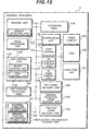
- the scanner apparatus 10 is constructed by: a reading unit 111 for reading an original; an image processing unit 112 for executing an image process to the read-out image; the USB control unit 113 which functions as one of USB devices with respect to the PC 30, functions as a hub (HUB) with respect to the printer apparatus 20, and is used for making USB-communication in accordance with a USB protocol; an operation panel 114 having a plurality of keys for allowing the operator to execute the operation setting of the scanner apparatus 10 and the like; a compressing unit 115 for compressing data formed by reading the original; a copy control unit 116 for making the printer apparatus 20 operative on the basis of the data obtained by reading the original, thereby allowing the original to be copied; a PC scanner control unit 117 for controlling the operation as a scanner on the basis of a control command from the PC 30; a PC print control unit 118 which makes control as a PC print for receiving the print data and the control command from the PC 30, transferring the received data and control command to the printer apparatus 20, and
- a CPU 120 makes substantial control of each of the above-mentioned units on the basis of programs held in a ROM (not shown). For simplicity of explanation, the scanner apparatus 10 will be described with respect to each of the foregoing functional blocks.
- the printer apparatus 20 which is connected to the scanner apparatus 10 by the USB cable 42 has: an emulation unit 201 for analyzing a printer language; a USB control unit 202 for transmitting and receiving the print data and control command between the scanner apparatus 10 and the printer apparatus 20 by USB-communication; an image memory 203 for storing the print data; a printing unit 204 for controlling a print engine to execute the printing process; and a decompressing unit 205 for decompressing the compressed print data which is transmitted.
- an emulation unit 201 for analyzing a printer language
- a USB control unit 202 for transmitting and receiving the print data and control command between the scanner apparatus 10 and the printer apparatus 20 by USB-communication
- an image memory 203 for storing the print data
- a printing unit 204 for controlling a print engine to execute the printing process
- a decompressing unit 205 for decompressing the compressed print data which is transmitted.
- a CPU 206 makes substantial control of each of the above-mentioned units on the basis of programs held in the ROM (not shown). For simplicity of explanation, the printer apparatus 20 will be described with respect to each of the foregoing functional blocks.
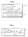
- the function information holding unit 150 of the scanner apparatus 10 has: a scanner function information holding unit 151 for holding the function information indicative of the functions of the scanner apparatus 10; and a printer function information holding unit 152 for holding the function information indicative of the functions of the printer apparatus 20. Either the function information held in the scanner function information holding unit 151 or the function information held in the printer function information holding unit 152 is read out when the device descriptor, which will be explained hereinafter, is formed.
- the USB control unit 113 of the scanner apparatus 10 is constructed by: the device control unit 1131 for functioning as one of the USB devices; and a host control unit 1132 for functioning as a hub.
- the host control unit 1132 has: a Tx buffer (Tx Buff) 11321 for transmitting the data to the printer apparatus 20; and an Rx buffer (Rx Buff) 11322 for receiving the data from the printer apparatus 20.
- Tx Buff Tx buffer
- Rx Buff Rx buffer
- the device control unit 1131 has: an Rx buffer (Rx Buff) 11311 for receiving the data from the PC 30; a Tx buffer (Tx Buff) 11312 for transmitting the data to the PC 30; and a multi-descriptor forming unit 11313 having a plurality of descriptor forming units (not shown) each for forming a device descriptor, which will be explained hereinafter.
- Rx Buff Rx buffer
- Tx Buff Tx buffer
- the multi-descriptor forming unit 11313 is constructed by: a resetting unit 11314 for executing bus resetting in the USB-connection; a scanner descriptor forming unit 11315 for forming a device descriptor for the scanner (hereinafter, referred to as a scanner device descriptor); and a printer descriptor forming unit 11316 for forming a device descriptor for the printer (hereinafter, referred to as a printer device descriptor).
- the scanner descriptor forming unit 11315 reads out the scanner function information from the scanner function information holding unit 151 in the function information holding unit 150 and forms the device descriptor in which the scanner function information is shown.
- the printer descriptor forming unit 11316 reads out the printer function information from the printer function information holding unit 152 in the function information holding unit 150 and forms the device descriptor in which the printer function information is shown. In this manner, the device descriptor is formed in accordance with the function to be controlled by the PC 30. The formed device descriptor is notified to the PC after the bus resetting in the USB-connection. The PC which received the notification specifies the communication partner destination on the basis of the function information shown in the device descriptor (makes device definition).
- the operation panel 114 When the selecting instruction is received from the operator, the operation panel 114 outputs a selection signal according to the instruction to the USB control unit 113.
- the multi-descriptor forming unit 11313 of the USB control unit 113 which received the selection signal activates either the scanner descriptor forming unit 11315 or the printer descriptor forming unit 11316 on the basis of the selection signal.
- the scanner descriptor forming unit 11315 is activated and, when he presses a use button of the printer apparatus 20, the printer descriptor forming unit 11316 is activated.
- the operation panel 114 for outputting the selection signal will now be described.
- the operation panel 114 of the scanner apparatus 10 has: an LCD display 1141 for allowing the operator to set the operation; a plurality of pressing keys 1142; and a PC-scanner key 1143.
- the operation panel 114 In correspondence to depressed ones of the plurality of keys 1142, the operation panel 114 outputs the selection signal (selection information) according to the pressed keys to the USB control unit 113. On the basis of the received selection signal, the multi-descriptor forming unit 11313 in the USB control unit 113 selects either the scanner descriptor forming unit 11315 or the printer descriptor forming unit 11316 and activates the selected forming unit.
- the operation panel 114 When the PC-scanner key 1143 is pressed, the operation panel 114 outputs a signal indicative of the PC-scan selection to the USB control unit 113.
- the USB control unit 113 selects the scanner descriptor forming unit 11315 in the multi-descriptor forming unit 11313 and activates the scanner descriptor forming unit 11315.
- the key event delivery unit 122 which received the information transfers the information to the device control unit 1131 in the USB control unit 113.
- the device control unit 1131 which received the information executes the bus resetting in the USB-connection by the resetting unit 11314 and forms the device descriptor by the multi-descriptor forming unit 11313.
- the bus resetting is executed, the communication between the PC 30 and the scanner apparatus 10 is started by the control transfer. The formed device descriptor is notified to the PC 30.
- the device descriptor formed by the scanner apparatus 10 is sent from the scanner apparatus 10 to the PC 30.
- the PC 30 allocates an address for accessing the scanner apparatus 10 to the scanner and makes the device definition. After that, the PC 30 communicates with the scanner apparatus 10 by using the set address.
- the device descriptor is divided into a plurality of parts and transmitted from the scanner apparatus 10 to the PC 30.
- main information of the device descriptor is transmitted from the scanner apparatus 10 to the PC 30.
- the PC 30 issues an obtaining request of detailed information of the device descriptor to the scanner apparatus 10.
- the scanner apparatus 10 which received the request outputs the necessary detailed information to the PC 30.
- Information regarding resources of the scanner apparatus 10, for example, information such as using method of the pipe, ID (identification) code, and the like is included in the necessary detailed information.
- the PC 30 searches for the device driver with reference to the ID code and activates the corresponding driver. When the setup of the scanner apparatus 10 is completed in this manner, the scanner apparatus 10 can provide the functions described in the device descriptor.
- the PC 30 detects the connection of the scanner apparatus 10 and, thereafter, executes the bus resetting. Since the operation after the bus resetting is similar to that of the contents mentioned above, its description is omitted here.
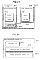
- the initializing unit 121 of the scanner apparatus 10 has a function for arbitrarily notifying the PC 30 of the device descriptor upon initialization. Specifically speaking, as shown in Fig. 7, the initializing unit 121 has: a default device descriptor table 121 in which the forming unit of the device descriptor (the scanner descriptor forming unit 11315 or the printer descriptor forming unit 11316) is made to correspond to a table number; and a default device descriptor table value storing area 1212 in which the table numbers to refer to the table upon initialization have been stored.
- a corresponding table 1213 in which the scanner descriptor forming unit 11315 is made to correspond to the table No. 1; and a corresponding table 1214 in which the printer descriptor forming unit 11316 is made to correspond to the table No. 2 are shown in the default device descriptor table 1211.
- An arbitrary table number has been stored in the default device descriptor table value storing area 1212.
- the forming unit of the device descriptor to be notified to the PC 30 upon initialization is selected in accordance with the table number shown in the default device descriptor table value storing area 1212.
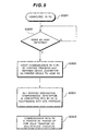
- the initializing process of the scanner apparatus is started by the initializing unit 121 (step S0801)
- the value in the default device descriptor table value storing area 1212 is discriminated (S0802). If it is equal to "1", the activation of the scanner descriptor forming unit 11315 is selected by the default device descriptor table 1211. Thus, the device descriptor in which the scanner function information is shown is formed by the scanner descriptor forming unit 11315. After that, the scanner descriptor is transmitted to the PC 30 by the device control unit 1131 in the USB control unit 113 (S0805).
- the activation of the printer descriptor forming unit 11316 is selected by the default device descriptor table 1211.
- the device descriptor in which the printer function information is shown is formed by the printer descriptor forming unit 1131C. After that, the printer descriptor is transmitted to the PC 30 by the device control unit 1131 in the USB control unit 113 (S0804).
- the PC 30 recognizes the connection of the new device and executes the bus resetting of the USB.
- the scanner apparatus 10 activates the printer descriptor forming unit 11316.
- the printer descriptor is formed by the printer descriptor forming unit 11316.
- the formed printer descriptor is transmitted from the scanner apparatus 10 to the PC 30 (S0903).
- the PC 30 which obtained the printer descriptor executes address designation and sets a configuration descriptor, an interface descriptor, and the like in accordance with a USB protocol (S0904).
- a pipe for a bulk transfer or isochronous transfer is established and the scanner apparatus 10 starts the USB-communication with the PC 30 as a printer by the pipe (S0905).
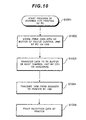
- the print data is transmitted from the PC 30 to the scanner apparatus 10 through the USB cable 41.
- the USB control unit 113 of the scanner apparatus 10 receives the print data (S1001), the print data is stored into the Rx buffer 11311 of the device control unit 1131 (S1002).
- the data stored in the Rx buffer 11311 of the device control unit 1131 is transferred to the Tx buffer 11321 of the host control unit 1132 by the CPU or hardware (S1003). Subsequently, the print data stored in the Tx buffer 11321 of the host control unit 1132 of the USB control unit 113 is transmitted to the printer apparatus 20 by the control of a host controller of the PC 30 (S1004). The printer apparatus 20 executes the printing process on the basis of the received print data (S1005).
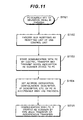
- the scanner apparatus 10 starts the communication with the PC 30 by the control transfer (that is, the USB control unit 113 transmits the scanner descriptor to the PC 30) (S1103).
- the PC 30 obtains information called address designation, configuration descriptor, and interface descriptor and makes various settings (S1104).
- a transmission path called a pipe for the bulk transfer or isochronous transfer is determined and the PC starts the USB-communication with the scanner apparatus 10 (S1105).
- the PC 30 is notified of the device descriptor after the bus resetting.
- the PC 30 can specify the communication partner destination on the basis of the single function information shown in the notified device descriptor, make the device definition of the specified communication partner destination, and make the USB-communication.
- the scanner apparatus 10 in the embodiment 1 by notifying the PC 30 of the device descriptor in which only one function information is shown, the communication partner destination can be specified on the basis of the single function information shown in the device descriptor.
- the dedicated driver to select the function and issue a switching command of the connecting construction (vendor request) is unnecessary. Thus, there is no need to develop the dedicated driver and, naturally, the troublesomeness to install the dedicated driver into the PC 30 can be eliminated.
- the scanner apparatus 10 in the embodiment 1 there is no need to provide a special IC chip for setting an end point into each of the scanner apparatus 10 and the printer apparatus 20 and an increase in manufacturing costs of the scanner apparatus 10 and the printer apparatus 20 can be suppressed.
- the scanner apparatus 10 can be fixed to the PC-printer function (or PC-scanner function) and used. The user can use the function which has been set to a default without being aware of the setting of use of the scanner apparatus 10.
- the scanner apparatus 10 When the scanner apparatus 10 is connected to the PC 30 by hot plug-in, by fixing so as to always form the device descriptor for the printer (or scanner) and transmitting the device descriptor for the printer (or scanner) to the PC 30, at the time of hot plug-in, the scanner apparatus can be fixed to the PC-printer function (or PC-scanner function) and used. Therefore, the scanner apparatus 10 can be used without confusing the operator.
- the scanner apparatus In the case of setting the scanner apparatus so as to operate as a PC-printer function at the time of initialization, power-on, or hot plug-in connection as well, by pressing the PC-scanner key 1143 on the operation panel 114, the scanner apparatus can be used by switching from the PC-printer function to the PC-scanner function. The use efficiency of the operator can be improved,
- the functions of the construction of the scanner apparatus 10 in the embodiment 1 are changed and new functions are added.
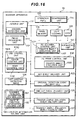
- the construction of the scanner apparatus 11 in the embodiment 2 differs from that of the embodiment 1 with respect to the following component elements: a reading unit 111' for reading the original; a USB control unit 113A; an original detection event delivery unit 123 for, when it is detected that the original has been put in the reading unit, transmitting information indicative of the detection to the device control unit 1131 of the USB control unit 113A; a left-original detecting timer 124 for detecting that the state where the original has been put in the reading unit continued for a predetermined time or more; and a time-out event delivery unit 125 for, when a time-out signal is received from the left-original detecting timer 124, transmitting information indicative of the detection of the left-original to the device control unit 1131 of the USB control unit 113A.
- the reading unit 111' has an original detecting unit 1111 for detecting that the original has been put.
- the original detecting unit 1111 transmits an original detection signal indicating that the original has been put to the original detection event delivery unit 123 and the left-original detecting timer 124.
- the original detection event delivery unit 123 which received the original detection signal transmits the information indicative of the detection of the original to the USB control unit 113A.
- the USB control unit 113A selects the scanner descriptor forming unit 11315 and transmits the scanner descriptor formed in the scanner descriptor forming unit 11315 to the PC 30.
- the left-original detecting timer 124 starts the time counting operation.
- the timer 124 transmits the time-out signal to the time-out event delivery unit 125.
- the time-out event delivery unit 125 which received the time-out signal transmits the information indicative of the detection of the left-original to the device control unit 1131 of the USB control unit 113A.
- the left-original to the device control unit 1131 of the USB control unit 113A selects the printer descriptor forming unit 11316 and transmits the printer descriptor formed by the printer descriptor forming unit 11316 to the PC 30.
- the original detecting unit 1111 detects that the original has been put (S1302) and outputs the original detection signal to the original detection event delivery unit 123 and the left-original detecting timer 124.
- the left-original detecting timer 124 which received the original detection signal starts the time counting operation (S1303).
- the original detection event delivery unit 123 which received the original detection signal transmits the information indicative of the detection of the original to the device control unit 1131 of the USB control unit 113A (S1304).
- the device control unit 1131 which received the information indicative of the detection of the original selects the scanner descriptor forming unit 11315 and executes the bus resetting so as to transmit the scanner descriptor formed by the scanner descriptor forming unit 11315 to the PC 30.
- the scanner descriptor is sent from the scanner apparatus 11 to the PC 30 (S1305).
- the PC 30 makes the device definition on the basis of the obtained scanner descriptor. Thus, the PC 30 can recognize that the scanner apparatus 11 operates by the scanner function (S1306).
- the left-original detecting timer 124 When the PC scan is not executed by the instruction of the operator in spite of the fact that the original has been put in the reading unit 111', if a time interval of, for example, 5 minutes has been set as a left-original detecting time, the left-original detecting timer 124 times out after the elapse of 5 minutes and outputs the time-out signal to the time-out event delivery unit 125 (S1307).
- the time-out event delivery unit 125 which received the time-out signal outputs the information indicative of the detection of the left-original to the USB control unit 113A (S 1308).
- the device control unit 1131 of the USB control unit 113A which received the information indicative of the detection of the left-original selects the printer descriptor forming unit 11316 by the multi-descriptor forming unit 11313 and transmits the printer descriptor formed by the printer descriptor forming unit 11316 to the PC 30 by the control transfer after the bus resetting (S1309).
- the PC 30 makes the device definition on the basis of the obtained printer descriptor. Thus, the PC 30 can make the printer apparatus 20 operative through the scanner apparatus 11.
- the original detecting unit 1111 is provided for the reading unit 111' and, when it is detected that the original has been left, the USB control unit 113A selects the scanner descriptor forming unit 11315 and transmits the scanner descriptor formed by the scanner descriptor forming unit 11315 to the PC 30, so that the PC 30 can make the device definition on the basis of the scanner descriptor.
- the PC-scanner function can be used and the use efficiency of the operator can be improved.
- the left-original detecting timer 124 detects the left-original, the function of the scanner apparatus 11 is switched to the PC-printer function. Therefore, when the original is left without reading the original by the reading unit 111', the operator can use the scanner apparatus 11 as a PC-printer function.
- a scanner apparatus 12 in the embodiment 3 the following component elements are added to the construction of the scanner apparatus 11 in the embodiment 2: a USB control unit 113B in place of the USB control unit 113A; a PC print control unit 118' for making control for the PC printer; and a printer simple emulation event delivery unit 126 for transmitting information indicative of detection of a command to switch the device descriptor from the printer descriptor to the scanner descriptor to the USB control unit 113B.
- the PC print control unit 118' has a printer simple emulation unit (specific information extracting unit) 1181 for analyzing the printer language sent from the PC 30 and detecting the "command to switch the device descriptor from the printer descriptor to the scanner descriptor" (specific information).
- a printer simple emulation unit (specific information extracting unit) 1181 for analyzing the printer language sent from the PC 30 and detecting the "command to switch the device descriptor from the printer descriptor to the scanner descriptor" (specific information).
- the ordinary PC-printer function is executed.
- the printer simple emulation event delivery unit 126 transmits information indicative of the "command to switch the device descriptor" to the USB control unit 113B.
- the printer driver transmits the command to switch the device descriptor from the printer descriptor to the scanner descriptor to the scanner apparatus 12 (S1501).
- the scanner apparatus 12 which received the command detects the "command to switch the device descriptor from the printer descriptor to the scanner descriptor" in the printer simple emulation unit 1181 of the PC print control unit 118' (S1502), the printer simple emulation event delivery unit 126 is notified of the detection.
- the printer simple emulation event delivery unit 126 which received the notification outputs information indicative of the detection of the "command to switch the device descriptor from the printer descriptor to the scanner descriptor" to the USB control unit 113B (S1503).
- the device control unit 1131 of the USB control unit 113B which received the information selects the scanner descriptor forming unit 11315 by the multi-descriptor forming unit 11313 and transmits the scanner descriptor formed by the scanner descriptor forming unit 11315 to the PC 30 by the control transfer after the bus resetting (S1504).
- the PC 30 makes the device definition on the basis of the obtained scanner descriptor.
- the PC 30 recognizes the scanner apparatus 12 as a scanner function and the PC-scanner function is validated.
- the scanner apparatus 12 in the embodiment 3 when the printer language is analyzed by the printer simple emulation unit 1181 and the "command to switch the device descriptor from the printer descriptor to the scanner descriptor" is detected, by switching the device descriptor to the printer descriptor and notifying the PC 30 of the scanner descriptor, the PC 30 makes the device definition on the basis of the scanner descriptor and switches the connecting construction.
- the apparatus can be used as a PC-scanner function and the use efficiency of the operator can be improved.
- a scanner apparatus 13 in the embodiment 4 differs from the scanner apparatus 12 in the embodiment 3 with respect to a point that a "command to switch the device descriptor from the scanner descriptor to the printer descriptor" is detected.
- the following component elements are added to the construction of the scanner apparatus 12 in the embodiment 3: a USB control unit 113C in place of the USB control unit 113B; a PC scanner control unit 117' for making control for the PC printer; and a scanner simple emulation event delivery unit 127 for transmitting information indicative of detection of the command to switch the device descriptor from the scanner descriptor to the printer descriptor to the USB control unit 113C.
- the PC scanner control unit 117' has a scanner simple emulation unit (specific information extracting unit) 1171 for analyzing the scanner language sent from the PC 30 and detecting the "command to switch the device descriptor from the scanner descriptor to the printer descriptor" (specific information).
- a scanner simple emulation unit (specific information extracting unit) 1171 for analyzing the scanner language sent from the PC 30 and detecting the "command to switch the device descriptor from the scanner descriptor to the printer descriptor" (specific information).
- the scanner simple emulation event delivery unit 127 transmits information indicative of the "command to switch the device descriptor" to the USB control unit 113C.
- the scanner driver transmits the command to switch the device descriptor from the scanner descriptor to the printer descriptor to the scanner apparatus 13 (S1701).
- the scanner apparatus 13 which received the command detects the "command to switch the device descriptor from the scanner descriptor to the printer descriptor" in the scanner simple emulation unit 1171 of the PC scanner control unit 117' (S 1702)
- the scanner simple emulation event delivery unit 127 is notified of the detection.
- the scanner simple emulation event delivery unit 127 which received the notification outputs information indicative of the detection of the "command to switch the device descriptor from the scanner descriptor to the printer descriptor" to the USB control unit 113C (S1703).
- the device control unit 1131 of the USB control unit 113C which received the information selects the printer descriptor forming unit 11316 by the multi-descriptor forming unit 11313 and transmits the printer descriptor formed by the printer descriptor forming unit 11316 to the PC 30 by the control transfer after the bus resetting (S1704).
- the PC 30 makes the device definition on the basis of the obtained printer descriptor.
- the PC 30 can make USB-communication with the printer apparatus 20 through the scanner apparatus 12.
- the scanner apparatus 13 in the embodiment 4 when the scanner language is analyzed by the scanner simple emulation unit 1171 and the "command to switch the device descriptor from the scanner descriptor to the printer descriptor" is detected, by switching the device descriptor to the scanner descriptor and notifying the PC 30 of the printer descriptor, the PC 30 makes the device definition on the basis of the printer descriptor and switches the connecting construction.
- the apparatus can be used as a PC-printer function and the use efficiency of the operator can be improved.
- a USB control unit 113D in place of the USB control unit 113C; a PC scan operation end event delivery unit 128 for transmitting information indicative of the end of the PC scanner function to the USB control unit 113D; and a PC print operation end event delivery unit 129 for transmitting information indicative of the end of the PC-printer function to the USB control unit 113D.
- the PC scan operation end event delivery unit 128 transmits PC scan end information to the device control unit 1131 of the USB control unit 113D.
- the PC print operation end event delivery unit 129 transmits the PC print end information to the device control unit 1131 of the USB control unit 113D.
- the device control unit 1131 of the USB control unit 113D selects the printer descriptor forming unit 11316 by the multi-descriptor forming unit 11313 and transmits the printer descriptor formed by the printer descriptor forming unit 11316 to the PC 30.
- the device control unit 1131 which received the PC print end information selects the scanner descriptor forming unit 11315 by the multi-descriptor forming unit 11313 and transmits the scanner descriptor formed by the scanner descriptor forming unit 11315 to the PC 30.
- the end of the PC scanning operation is monitored in the reading unit 111' (S1902).
- the PC scan operation end event delivery unit 128 is notified of the PC scan end information.
- the PC scan operation end event delivery unit 128 transmits information indicative of the end of the PC scanning operation to the USB control unit 113D (S1903).
- the device control unit 1131 of the USB control unit 113D which received the PC scanning operation end information selects the printer descriptor forming unit 11316 from the two descriptor forming units by the multi-descriptor forming unit 11313 and transmits the printer descriptor formed by the selected printer descriptor forming unit 11316 to the PC 30 by the control transfer after the bus resetting was executed (S1904). Since the subsequent operation is similar to the contents described in the foregoing embodiment, its explanation is omitted here. The PC printing function is validated after similar processing steps are executed.
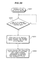
- the end of the PC printing operation is monitored (S2002).
- the PC print operation end event delivery unit 129 which detected the end of the PC printing operation transmits information indicative of the end of the printing operation to the USB control unit 113D (S2003).
- the device control unit 1131 of the USB control unit 113D which received the PC printing operation end information selects the scanner descriptor forming unit 11315 from the two descriptor forming units by the multi-descriptor forming unit 11313 and transmits the scanner descriptor formed by the selected scanner descriptor forming unit 11315 to the PC 30 by the control transfer after the bus resetting was executed (S2004). Since the subsequent operation is similar to the contents described in the foregoing embodiment, its explanation is omitted here.
- the PC scanning function is validated after similar processing steps are executed.
- the device control unit 1131 of the USB control unit 113D forms the device descriptor for allowing the scanner apparatus to function as a PC printing operation on the basis of the information from the PC scan operation end event delivery unit 128 and notifies the PC 30 of the device descriptor.
- the device control unit 1131 of the USB control unit 113D forms the device descriptor for allowing the scanner apparatus to function as a PC scanning printing operation on the basis of the information from the PC print operation end event delivery unit 129 and notifies the PC 30 of the device descriptor.
- the function which is mainly used by the operator can be automatically switched to the function which is mainly used by the operator.
- the use efficiency of the operator can be improved.
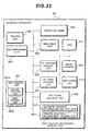
- the printer apparatus 60 has: a printing unit 601 for printing onto a sheet; a decompressing unit 602 for decompressing compressed print data; a USB control unit 603 which functions as one of the USB devices with respect to the PC 80, functions as a hub with respect to the scanner apparatus 70, and is used to make USB-connection in accordance with a USB protocol; an operation panel 604 on which a plurality of keys for making operation setting of the printer apparatus 60 by the operator and the like are provided; an emulation unit 605 for decoding a printer control language; a PC scanner control unit 606 which temporarily receives a control command for the PC scanner by the printer apparatus 60, transfers the received control command to the scanner apparatus 70, and is used to control the scanner apparatus so as to function as a PC scanner; a PC print control unit 607 for controlling the apparatus so as to function as a PC printer; an image memory 609 which is used as a work area for holding the print image data and executing the image process and the compressing process; an initializing
- a CPU 611 makes substantial control of each of the above-mentioned units on the basis of the programs held in the ROM (not shown). For simplicity of explanation, the printer apparatus 60 will be described with respect to each of the foregoing functional blocks.
- the function information holding unit 650 of the printer apparatus 601 has: a scanner function information holding unit 651 for holding the function information indicative of the functions of the scanner apparatus 70; and a printer function information holding unit 652 for holding the function information indicative of the functions of the printer apparatus 60. Either the function information held in the scanner function information holding unit 651 or the function information held in the printer function information holding unit 652 is read out when the device descriptor, which will be explained hereinafter, is formed.
- the USB control unit 603 of the printer apparatus 60 is constructed by: the device control unit 6031 for functioning as one of the USB devices; and a host control unit 6032 for functioning as a hub.
- the host control unit 6032 has: a Tx buffer (Tx Buff) 60321 for transmitting the data to the scanner apparatus 70; and an Rx buffer (Rx Buff) 60322 for receiving the data from the scanner apparatus 70.
- Tx Buff Tx buffer
- Rx Buff Rx buffer
- the device control unit 6031 has: an Rx buffer (Rx Buff) 60311 for receiving the data from the PC 80; a Tx buffer (Tx Buff) 60312 for transmitting the data to the PC 80; and a multi-descriptor forming unit 60313 having a plurality of descriptor forming units (not shown) each for forming a device descriptor, which will be explained hereinafter.
- Rx Buff Rx buffer
- Tx Buff Tx buffer
- multi-descriptor forming unit 60313 having a plurality of descriptor forming units (not shown) each for forming a device descriptor, which will be explained hereinafter.
- the multi-descriptor forming unit 60313 is constructed by: a resetting unit 60314 for executing bus resetting in the USB-connection; a scanner descriptor forming unit 60315 for forming a scanner device descriptor; and a printer descriptor forming unit 60316 for forming a printer device descriptor.
- the scanner descriptor forming unit 60315 reads out the scanner function information from the scanner function information holding unit 651 in the function information holding unit 650 and forms the device descriptor in which the scanner function information is shown.
- the printer descriptor forming unit 60316 reads out the printer function information from the printer function information holding unit 652 in the function information holding unit 650 and forms the device descriptor in which the printer function information is shown. In this manner, the device descriptor is formed in accordance with the function to be controlled by the PC 80. The formed device descriptor is notified to the PC after the bus resetting in the USB-connection. The PC which received the notification specifies the communication partner destination on the basis of the function information shown in the device descriptor (makes device definition).
- the operation panel 604 of the printer apparatus 60 has: an LCD display 6041 for allowing the operator to set the operation; a plurality of pressing keys 6042; and a PC-scanner key 6043.
- the operation panel 604 In correspondence to depressed ones of the plurality of keys 6042, the operation panel 604 outputs the selection signal (selection information) according to the pressed keys to the USB control unit 603.
- the multi-descriptor forming unit 60313 in the USB control unit 603 selects either the scanner descriptor forming unit 60315 or the printer descriptor forming unit 60316 and activates the selected forming unit.
- the scanner descriptor forming unit 60315 is activated.
- the printer descriptor forming unit 60316 is activated.
- the operation panel 604 When the PC-scanner key 6043 is pressed, the operation panel 604 outputs a signal indicative of the PC-scan selection to the USB control unit 603.
- the USB control unit 603 which received the selection signal indicative of the selection of the PC-scanning function selects the scanner descriptor forming unit 60315 in the multi-descriptar forming unit 60313, activates the scanner descriptor forming unit 60315, and forms the device descriptor.
- the PC 80 is notified of the formed device descriptor after the bus resetting in the USB-connection is executed in the resetting unit 60314. Since the operation after the bus resetting is similar to that in the foregoing embodiment, its description is omitted here.
- the initializing unit 610 of the printer apparatus 60 has a function for arbitrarily notifying the PC 80 of the device descriptor at the time of the initialization.
- the initializing unit 610 has: a default device descriptor table 6101 in which the forming unit of the device descriptor (the scanner descriptor forming unit 60315 or the printer descriptor forming unit 60316) is made to correspond to a table number; and a default device descriptor table value storing area 6102 in which the table numbers to refer to the table upon initialization have been stored.
- a corresponding table 6103 in which the scanner descriptor forming unit 60315 is made to correspond to the table No. 1 and a corresponding table 6104 in which the printer descriptor forming unit 60316 is made to correspond to the table No. 2 are shown in the default device descriptor table 1211.
- An arbitrary table number has been stored in the default device descriptor table value storing area 6102.
- the forming unit of the device descriptor to be notified to the PC 80 upon initialization is selected in accordance with the table number shown in the default device descriptor table value storing area 6102.
- step S2701 when the initializing process of the scanner apparatus is started by the initializing unit 610 (step S2701), the value in the default device descriptor table value storing area 6102 is discriminated (S2702). If it is equal to "1", the activation of the scanner descriptor forming unit 60315 is selected by the default device descriptor table 6101. Thus, the device descriptor in which the scanner function information is shown is formed by the scanner descriptor forming unit 60315. After that, the scanner descriptor is transmitted to the PC 80 by the device control unit 6031 in the USB control unit 603 (S2705).
- the activation of the printer descriptor forming unit 60316 is selected by the default device descriptor table 6101.
- the device descriptor in which the printer function information is shown is formed by the printer descriptor forming unit 60316. After that, the printer descriptor is transmitted to the PC 80 by the device control unit 6031 in the USB control unit 603 (S2704).
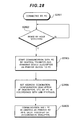
- the PC 80 When the scanner apparatus 70 is connected to the PC 80 by the hot plug-in (S2801), the PC 80 recognizes the connection of the new device and executes the bus resetting of the USB by the resetting unit 60314. When the resetting from the PC 80 is detected (S2802), the printer apparatus 60 activates the printer descriptor forming unit 60316. The printer descriptor is formed by the printer descriptor forming unit 60316.
- the formed printer descriptor is transmitted from the printer apparatus 60 to the PC 80 by the control transfer (S2803).
- the PC 80 which obtained the printer descriptor executes the address designation and sets the configuration descriptor, the interface descriptor, and the like in accordance with the USB protocol (S2804).
- a pipe for a bulk transfer or isochronous transfer is established and the printer apparatus 60 starts the USB-communication with the PC 80 as a printer device by the pipe (S2805).
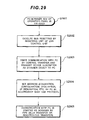
- the key event delivery unit 608 notifies the USB control unit 603 of information showing that the PC-scanner key 6043 has been depressed.
- the USB control unit 603 which received the information selects the scanner descriptor forming unit 60315.
- the selected scanner descriptor forming unit 60315 forms the scanner descriptor.
- the printer apparatus 60 starts the communication with the PC 80 by the control transfer. That is, the device control unit 6031 of the printer apparatus 60 transmits the scanner descriptor to the PC 80 (S2903).
- the PC 80 obtains the information called address designation, configuration descriptor, and interface descriptor and makes various settings on the basis of the scanner descriptor (S2904). By this setting, the transmission path called a pipe for the bulk transfer or isochronous transfer is determined.
- the printer apparatus 60 starts the USB-communication with the PC 80 as a printer device by the pipe (S2905).
- the printer apparatus 60 in the embodiment 6 only one function information whose selection has been instructed is read out so as to make the USB-communication by the function whose selection has been instructed by the operator through the operation panel 604.
- the PC 80 is notified of this device descriptor after the bus resetting.
- the PC 80 can specify the communication partner destination on the basis of the single notified function information shown in the device descriptor, makes the device definition of the specified communication partner destination, and can make the USB-communication.
- the printer apparatus 60 in the embodiment 6 by notifying the PC 80 of the device descriptor in which only one function information is shown, the communication partner destination can be specified on the basis of the single function information shown in the device descriptor and the dedicated driver to select the function and issue the switching command of the connecting construction (vendor request) is unnecessary. Therefore, there is no need to develop the dedicated driver and, naturally, the troublesomeness to install the dedicated driver into the PC 80 can be eliminated.
- peripherals to the printer apparatus and scanner apparatus
- the invention is not limited to them.
- the invention can be applied to, for example, a monitor apparatus, a keyboard, a mouse, a facsimile apparatus, a storing device, an image server apparatus, and the like as peripherals.
- the embodiments are not described with respect to the updating of the function information held in the function information holding unit 150 of the peripheral, for example, it is possible to construct the apparatus in such a manner that when the dependent peripheral is connected to the peripheral, the function information is obtained from the dependent peripheral, and the function information held in the function information holding unit 150 is updated or that the function information is obtained by communicating with an upper apparatus and the function information held in the function information holding unit 150 is updated.
- the function information held in the function information holding unit 150 can be also updated by exchanging a ROM in the peripheral.
- the function information of the peripheral and the function information of the dependent peripheral are preliminarily held in the function information holding unit 150 of the peripheral, one of the function information is read out as necessary, and the device descriptor is formed and notified to the upper apparatus.
- the invention is not limited to such an example. For instance, it is possible to construct the apparatus in such a manner that the device descriptor for the peripheral and the device descriptor for the dependent peripheral are preliminarily held and the upper apparatus is notified of one of the device descriptors in accordance with the selecting instruction.
- the invention is not limited to such an example.
- the device descriptor can be also made to correspond to the table number.
- the upper apparatus can be directly notified of the device descriptor which has been made to correspond to the table number.
- a peripheral for notifying a USB-connected upper apparatus of a device descriptor and allowing the upper apparatus to specify a communication partner destination by the function information shown in the device descriptor has: a peripheral function information holding unit which holds function information showing functions of the peripheral; a dependent peripheral function information holding unit which holds function information showing functions of a USB-connected dependent peripheral; and a USB control unit which reads out one of the function information held in those holding units by a selecting instruction and notifies the upper apparatus of the device descriptor in which the read-out function information is shown.
- a peripheral which can realize a multi-function without developing a dedicated driver and installing it into a PC is provided.
Landscapes
- Engineering & Computer Science (AREA)
- General Engineering & Computer Science (AREA)
- Computing Systems (AREA)
- Multimedia (AREA)
- Signal Processing (AREA)
- Facsimiles In General (AREA)
- Accessory Devices And Overall Control Thereof (AREA)
- Information Transfer Systems (AREA)
- Stored Programmes (AREA)
Abstract
Description
In the conventional system, however, since the dedicated driver for selecting the desired function from the plurality of functions and issuing the switching command of the connecting construction is needed and it is necessary to develop such a dedicated driver and install it into the PC as mentioned above, they cause a problem.
According to the present invention, there is provided a peripheral for notifying a USB-connected upper apparatus of a device descriptor and allowing the upper apparatus to specify a communication partner destination on the basis of function information shown in the device descriptor, comprising:
the peripheral function information holding unit holds the function information indicative of an image forming function, and the dependent peripheral function information holding unit holds the function information indicative of an image reading function.
Moreover, the peripheral may further comprise a timer which notifies the USB control unit of a left-original detection signal as the selecting instruction when it is detected that the original has been arranged and left, and wherein when the left-original detection signal is received, the USB control unit reads out the function information indicative of the image forming function.
Moreover, the peripheral may further comprise a specific information extracting unit which analyzes a control command from the upper apparatus and extracts specific information, and wherein when the specific information is a command described by a control language of an image forming apparatus, the specific information extracting unit notifies the USB control unit of the command as the selecting instruction, and when the command is received, the USB control unit reads out the function information indicative of the image forming function.
A corresponding table 1213 in which the scanner
A corresponding table 6103 in which the scanner
Claims (15)
- A peripheral for notifying a USB-connected upper apparatus of a device descriptor and allowing said upper apparatus to specify a communication partner destination on the basis of function information shown in said device descriptor, comprising:a peripheral function information holding unit which holds function information indicative of functions of said peripheral;a dependent peripheral function information holding unit which holds function information indicative of functions of a dependent peripheral which is USB-connected; anda USB control unit which reads out either the function information held in said peripheral function information holding unit or the function information held in said dependent peripheral function information holding unit on the basis of a selecting instruction and notifies said upper apparatus of the device descriptor in which the read-out function information is shown.
- The peripheral according to claim 1, wherein
when said peripheral is an image reading apparatus and said dependent peripheral is an image forming apparatus,
said peripheral function information holding unit holds the function information indicative of an image reading function, and
said dependent peripheral function information holding unit holds the function information indicative of an image forming function. - The peripheral according to claim 1, wherein
when said peripheral is an image forming apparatus and said dependent peripheral is an image reading apparatus,
said peripheral function information holding unit holds the function information indicative of an image forming function, and
said dependent peripheral function information holding unit holds the function information indicative of an image reading function. - The peripheral according to one of claims 1 - 3, further comprising an operation panel which receives said selecting instruction, and
wherein when said selecting instruction is received by said operation panel, said USB control unit executes bus resetting in the USB-connection with said upper apparatus before the notification of said device descriptor. - The peripheral according to claim 2 or 3, wherein said USB control unit has a multi-device descriptor forming unit which forms the device descriptor in which the function information which is read out by said selecting instruction is shown.
- The peripheral according to claim 5, further comprising an original reading unit which reads an original, and
wherein when it is detected that the original has been arranged, said original reading unit notifies said USB control unit of an original detection signal as said selecting instruction, and
when said original detection signal is received, said USB control unit reads out the function information indicative of the image reading function. - The peripheral according to claim 6, further comprising a timer which notifies said USB control unit of a left-original detection signal as said selecting instruction when it is detected that said original has been arranged and left, and
wherein when said left-original detection signal is received, said USB control unit reads out the function information indicative of the image forming function. - The peripheral according to claim 6, wherein
said original reading unit reads out the arranged original and, when it is detected that there are no originals to be read, notifies said USB control unit of an end detection signal as said selecting instruction, and
when said end detection signal is received, said USB control unit reads out the function information indicative of the image forming function. - The peripheral according to one of claims 1 to 8, further comprising a specific information extracting unit which analyzes a control command from said upper apparatus and extracts specific information, and
wherein when an instruction to execute bus resetting in the USB-connection with said upper apparatus is shown in said extracted specific information, said USB control unit executes said bus resetting. - The peripheral according to claim 5, further comprising a specific information extracting unit which analyzes a control command from said upper apparatus and extracts specific information, and
wherein when said specific information is a command described by a control language of an image reading apparatus, said specific information extracting unit notifies said USB control unit of said command as said selecting instruction, and
when said command is received, said USB control unit reads out the function information indicative of the image reading function. - The peripheral according to claim 5, further comprising a specific information extracting unit which analyzes a control command from said upper apparatus and extracts specific information, and
wherein when said specific information is a command described by a control language of an image forming apparatus, said specific information extracting unit notifies said USB control unit of said command as said selecting instruction, and
when said command is received, said USB control unit reads out the function information indicative of the image forming function. - The peripheral according to claim 10 or 11, wherein when information showing that a process based on said command has been finished is received as said selecting instruction, on the basis of said command, said USB control unit reads out the other function information which is not read out.
- The peripheral according to one of claims 1 to 12, wherein the USB-connection with said upper apparatus is hot plug-in connection, bus resetting in said USB-connection is executed by the hot plug-in connection.
- A peripheral for notifying a USB-connected upper apparatus of a device descriptor and allowing said upper apparatus to specify a communication partner destination on the basis of function information shown in said device descriptor, comprising:wherein said USB control unit has a host control section which executes a relay for communicating between said upper apparatus and said dependent peripheral, when said dependent peripheral is specified as said communication partner destination by said upper apparatus.a peripheral function information holding unit which holds function information indicative of functions of said peripheral;a dependent peripheral function information holding unit which holds function information indicative of functions of a dependent peripheral which is USB-connected; anda USB control unit which reads out either the function information held in said peripheral function information holding unit or the function information held in said dependent peripheral function information holding unit on the basis of a selecting instruction and notifies said upper apparatus of the device descriptor in which the read-out function information is contained,
- The peripheral according to claim 14, wherein said peripheral is a scanner; said dependent peripheral is a printer.
Priority Applications (1)
| Application Number | Priority Date | Filing Date | Title |
|---|---|---|---|
| EP10178243.1A EP2273775B1 (en) | 2004-04-27 | 2005-04-27 | Peripherals of computer |
Applications Claiming Priority (2)
| Application Number | Priority Date | Filing Date | Title |
|---|---|---|---|
| JP2004132008 | 2004-04-27 | ||
| JP2004132008 | 2004-04-27 |
Related Child Applications (2)
| Application Number | Title | Priority Date | Filing Date |
|---|---|---|---|
| EP10178243.1A Division EP2273775B1 (en) | 2004-04-27 | 2005-04-27 | Peripherals of computer |
| EP10178243.1 Division-Into | 2010-09-22 |
Publications (3)
| Publication Number | Publication Date |
|---|---|
| EP1592221A2 true EP1592221A2 (en) | 2005-11-02 |
| EP1592221A3 EP1592221A3 (en) | 2007-02-28 |
| EP1592221B1 EP1592221B1 (en) | 2013-10-09 |
Family
ID=34939554
Family Applications (2)
| Application Number | Title | Priority Date | Filing Date |
|---|---|---|---|
| EP05103466.8A Ceased EP1592221B1 (en) | 2004-04-27 | 2005-04-27 | Peripherals of computer |
| EP10178243.1A Ceased EP2273775B1 (en) | 2004-04-27 | 2005-04-27 | Peripherals of computer |
Family Applications After (1)
| Application Number | Title | Priority Date | Filing Date |
|---|---|---|---|
| EP10178243.1A Ceased EP2273775B1 (en) | 2004-04-27 | 2005-04-27 | Peripherals of computer |
Country Status (3)
| Country | Link |
|---|---|
| US (2) | US7177972B2 (en) |
| EP (2) | EP1592221B1 (en) |
| CN (1) | CN100514315C (en) |
Cited By (1)
| Publication number | Priority date | Publication date | Assignee | Title |
|---|---|---|---|---|
| CN101064889B (en) * | 2006-04-28 | 2012-01-04 | 联发科技股份有限公司 | Apparatus and method for selectively activating functions of a portable device |
Families Citing this family (24)
| Publication number | Priority date | Publication date | Assignee | Title |
|---|---|---|---|---|
| US7904943B2 (en) | 2004-12-28 | 2011-03-08 | O'connor Dennis M | Secure controller for block oriented storage |
| US7412579B2 (en) * | 2004-12-30 | 2008-08-12 | O'connor Dennis M | Secure memory controller |
| JP4618021B2 (en) * | 2005-07-06 | 2011-01-26 | 富士ゼロックス株式会社 | Image reading apparatus, image forming apparatus, image processing system, storage area sharing method of image reading apparatus, and storage area sharing method of image processing system |
| JP4971610B2 (en) * | 2005-09-01 | 2012-07-11 | キヤノン株式会社 | Program and method for managing device driver and information processing apparatus |
| JP2007081893A (en) * | 2005-09-15 | 2007-03-29 | Ricoh Co Ltd | Image input device and printing system |
| US7668107B2 (en) * | 2006-03-22 | 2010-02-23 | Marvell Israel (M.I.S.L.) Ltd. | Hardware implementation of network testing and performance monitoring in a network device |
| US7715660B2 (en) * | 2006-06-13 | 2010-05-11 | Alpha Imaging Technology Corp. | Image acquisition device |
| US7752029B2 (en) * | 2006-06-23 | 2010-07-06 | Kyocera Mita Corporation | Method to change USB device descriptors from host to emulate a new device |
| US7707349B1 (en) * | 2006-06-26 | 2010-04-27 | Marvell International Ltd. | USB isochronous data transfer for a host based laser printer |
| US7962680B2 (en) * | 2006-12-05 | 2011-06-14 | Ricoh Company, Ltd. | Image forming apparatus and connection notifying method |
| US7600156B2 (en) * | 2006-12-19 | 2009-10-06 | Dell Products, Lp | System, method, and device including built-in self tests for communication bus device |
| JP4333764B2 (en) * | 2007-03-28 | 2009-09-16 | ブラザー工業株式会社 | Device control system |
| JP4483887B2 (en) * | 2007-03-30 | 2010-06-16 | ブラザー工業株式会社 | Portable storage media |
| JP4513849B2 (en) * | 2007-10-24 | 2010-07-28 | ブラザー工業株式会社 | printer |
| JP2010044679A (en) * | 2008-08-18 | 2010-02-25 | Sony Corp | Information processor, information processing method and information processing system |
| JP4586089B2 (en) * | 2008-10-10 | 2010-11-24 | 株式会社ソニー・コンピュータエンタテインメント | COMMUNICATION SYSTEM, HOST DEVICE, AND TERMINAL DEVICE |
| ES2428394T3 (en) * | 2009-10-15 | 2013-11-07 | Seiko Epson Corporation | Electronic device, control method and recording medium |
| BRPI1004997A2 (en) * | 2009-11-11 | 2013-02-26 | Seiko Epson Corp | electronic device and control method |
| JP5664047B2 (en) * | 2010-09-13 | 2015-02-04 | セイコーエプソン株式会社 | Multifunction machine, control method of multi-function machine, and program |
| JP5795912B2 (en) * | 2011-09-07 | 2015-10-14 | キヤノン株式会社 | Image reading apparatus and image forming system |
| US9182996B2 (en) | 2013-03-12 | 2015-11-10 | Midnight Mosaic Llc | Methods and apparatus for USB tunneling through USB printer device class |
| JP6111782B2 (en) * | 2013-03-27 | 2017-04-12 | セイコーエプソン株式会社 | Printing device |
| CN105095118B (en) * | 2014-05-19 | 2019-08-30 | 小米科技有限责任公司 | The application method and device of equipment |
| US10719469B2 (en) * | 2017-02-28 | 2020-07-21 | Intel Corporation | Inband messaging method for integrated type-C universal serial bus detection using enhanced serial peripheral interconnect |
Family Cites Families (9)
| Publication number | Priority date | Publication date | Assignee | Title |
|---|---|---|---|---|
| US6473811B1 (en) * | 1998-03-13 | 2002-10-29 | Canon Kabushiki Kaisha | Method and apparatus for displaying a connection status of a device based on connection information |
| US7203787B2 (en) * | 1999-01-25 | 2007-04-10 | Canon Kabushiki Kaisha | Information processing apparatus and method that utilizes stored information about a mountable device |
| JP2000211216A (en) * | 1999-01-25 | 2000-08-02 | Canon Inc | Information processing method and system for composite device |
| JP2001007958A (en) * | 1999-06-25 | 2001-01-12 | Canon Inc | Image forming system, image forming apparatus, function setting method, and storage medium |
| JP2001222503A (en) | 2000-02-08 | 2001-08-17 | Ricoh Co Ltd | Peripheral device control system |
| TWI270786B (en) * | 2002-04-10 | 2007-01-11 | Avision Inc | Scanner capable of being a universal serial bus host |
| US20040148450A1 (en) * | 2003-01-27 | 2004-07-29 | Shih-Chang Chen | Serially connectable USB drive |
| JP2004343275A (en) * | 2003-05-14 | 2004-12-02 | Murata Mach Ltd | Image processing system and scanner |
| US20040260850A1 (en) * | 2003-06-17 | 2004-12-23 | Action Star Enterprise Co., Ltd. | Apparatus for USB interface identification |
-
2005
- 2005-04-26 CN CNB200510069871XA patent/CN100514315C/en not_active Expired - Fee Related
- 2005-04-26 US US11/113,996 patent/US7177972B2/en not_active Expired - Lifetime
- 2005-04-27 EP EP05103466.8A patent/EP1592221B1/en not_active Ceased
- 2005-04-27 EP EP10178243.1A patent/EP2273775B1/en not_active Ceased
-
2007
- 2007-01-04 US US11/649,219 patent/US7346729B2/en not_active Expired - Lifetime
Cited By (1)
| Publication number | Priority date | Publication date | Assignee | Title |
|---|---|---|---|---|
| CN101064889B (en) * | 2006-04-28 | 2012-01-04 | 联发科技股份有限公司 | Apparatus and method for selectively activating functions of a portable device |
Also Published As
| Publication number | Publication date |
|---|---|
| EP2273775A2 (en) | 2011-01-12 |
| US7346729B2 (en) | 2008-03-18 |
| EP1592221B1 (en) | 2013-10-09 |
| US7177972B2 (en) | 2007-02-13 |
| EP1592221A3 (en) | 2007-02-28 |
| US20070112997A1 (en) | 2007-05-17 |
| EP2273775B1 (en) | 2015-01-21 |
| EP2273775A3 (en) | 2011-03-09 |
| CN100514315C (en) | 2009-07-15 |
| CN1707452A (en) | 2005-12-14 |
| US20050240711A1 (en) | 2005-10-27 |
Similar Documents
| Publication | Publication Date | Title |
|---|---|---|
| EP1592221B1 (en) | Peripherals of computer | |
| CN102077165B (en) | Peripheral device and image reading device | |
| US7752029B2 (en) | Method to change USB device descriptors from host to emulate a new device | |
| CN101277362B (en) | Multifunction peripheral device and device control system | |
| US8051245B2 (en) | Information processing system capable of recognizing and accessing removable external storage device in simple scheme, method for controlling information processing system, and image input and output apparatus | |
| US7295338B2 (en) | Status information acquisition from plural functions included in image processing apparatus | |
| JP4182116B2 (en) | PRINT CONTROL DEVICE, ITS CONTROL METHOD, AND COMPUTER PROGRAM | |
| JP2001256170A (en) | Peripheral devices and printers | |
| JP2004303216A (en) | Information processing apparatus, image forming apparatus, error processing method at program startup, and recording medium | |
| US8179538B2 (en) | Image processing apparatus, information processing apparatus and control method | |
| JP4676241B2 (en) | Computer peripherals | |
| CN102404476B (en) | Image processing system and its method forming image | |
| JP2004129246A (en) | Image forming apparatus and application information acquisition method | |
| EP1286256A2 (en) | Method and apparatus for image data processing capable of performing a high speed processing using a risc and an AGP | |
| KR100282938B1 (en) | Host data transmission method and MFP data reception method | |
| JPH08289068A (en) | Composite digital copying machine | |
| JPH0774911A (en) | Format structure of control information for protocol control during transmission of image information between facsimile and computer system | |
| US20030189719A1 (en) | Recording control apparatus and control method using the same recording control apparatus | |
| US9134929B2 (en) | Information processing apparatus, information processing method and computer-readable recording medium | |
| JP2006293638A (en) | Information processing device and peripheral device | |
| JP6634841B2 (en) | Image storage device, image storage system and program | |
| JP3210571B2 (en) | Image input device and data processing method of image input device | |
| JP5739561B2 (en) | Peripheral device, image reading device and image reading system | |
| JP2005173888A (en) | Information processing apparatus, program recovery method, program recovery program, and recording medium | |
| JP2004015214A (en) | Image processing apparatus, control method for image processing apparatus, program, and information storage medium |
Legal Events
| Date | Code | Title | Description |
|---|---|---|---|
| PUAI | Public reference made under article 153(3) epc to a published international application that has entered the european phase |
Free format text: ORIGINAL CODE: 0009012 |
|
| AK | Designated contracting states |
Kind code of ref document: A2 Designated state(s): AT BE BG CH CY CZ DE DK EE ES FI FR GB GR HU IE IS IT LI LT LU MC NL PL PT RO SE SI SK TR |
|
| AX | Request for extension of the european patent |
Extension state: AL BA HR LV MK YU |
|
| PUAL | Search report despatched |
Free format text: ORIGINAL CODE: 0009013 |
|
| AK | Designated contracting states |
Kind code of ref document: A3 Designated state(s): AT BE BG CH CY CZ DE DK EE ES FI FR GB GR HU IE IS IT LI LT LU MC NL PL PT RO SE SI SK TR |
|
| AX | Request for extension of the european patent |
Extension state: AL BA HR LV MK YU |
|
| 17P | Request for examination filed |
Effective date: 20070813 |
|
| AKX | Designation fees paid |
Designated state(s): DE FR GB NL |
|
| 17Q | First examination report despatched |
Effective date: 20071119 |
|
| GRAJ | Information related to disapproval of communication of intention to grant by the applicant or resumption of examination proceedings by the epo deleted |
Free format text: ORIGINAL CODE: EPIDOSDIGR1 |
|
| GRAP | Despatch of communication of intention to grant a patent |
Free format text: ORIGINAL CODE: EPIDOSNIGR1 |
|
| RIN1 | Information on inventor provided before grant (corrected) |
Inventor name: WATANABE, YUICHI |
|
| GRAP | Despatch of communication of intention to grant a patent |
Free format text: ORIGINAL CODE: EPIDOSNIGR1 |
|
| INTG | Intention to grant announced |
Effective date: 20130503 |
|
| GRAS | Grant fee paid |
Free format text: ORIGINAL CODE: EPIDOSNIGR3 |
|
| GRAA | (expected) grant |
Free format text: ORIGINAL CODE: 0009210 |
|
| AK | Designated contracting states |
Kind code of ref document: B1 Designated state(s): DE FR GB NL |
|
| REG | Reference to a national code |
Ref country code: GB Ref legal event code: FG4D |
|
| REG | Reference to a national code |
Ref country code: DE Ref legal event code: R096 Ref document number: 602005041434 Country of ref document: DE Effective date: 20131205 |
|
| REG | Reference to a national code |
Ref country code: NL Ref legal event code: T3 |
|
| REG | Reference to a national code |
Ref country code: DE Ref legal event code: R097 Ref document number: 602005041434 Country of ref document: DE |
|
| PLBE | No opposition filed within time limit |
Free format text: ORIGINAL CODE: 0009261 |
|
| STAA | Information on the status of an ep patent application or granted ep patent |
Free format text: STATUS: NO OPPOSITION FILED WITHIN TIME LIMIT |
|
| 26N | No opposition filed |
Effective date: 20140710 |
|
| REG | Reference to a national code |
Ref country code: DE Ref legal event code: R097 Ref document number: 602005041434 Country of ref document: DE Effective date: 20140710 |
|
| REG | Reference to a national code |
Ref country code: FR Ref legal event code: PLFP Year of fee payment: 12 |
|
| REG | Reference to a national code |
Ref country code: FR Ref legal event code: PLFP Year of fee payment: 13 |
|
| REG | Reference to a national code |
Ref country code: FR Ref legal event code: PLFP Year of fee payment: 14 |
|
| PGFP | Annual fee paid to national office [announced via postgrant information from national office to epo] |
Ref country code: NL Payment date: 20200312 Year of fee payment: 16 |
|
| PGFP | Annual fee paid to national office [announced via postgrant information from national office to epo] |
Ref country code: FR Payment date: 20200312 Year of fee payment: 16 |
|
| PGFP | Annual fee paid to national office [announced via postgrant information from national office to epo] |
Ref country code: DE Payment date: 20200415 Year of fee payment: 16 |
|
| PGFP | Annual fee paid to national office [announced via postgrant information from national office to epo] |
Ref country code: GB Payment date: 20200416 Year of fee payment: 16 |
|
| REG | Reference to a national code |
Ref country code: DE Ref legal event code: R119 Ref document number: 602005041434 Country of ref document: DE |
|
| REG | Reference to a national code |
Ref country code: NL Ref legal event code: MM Effective date: 20210501 |
|
| GBPC | Gb: european patent ceased through non-payment of renewal fee |
Effective date: 20210427 |
|
| PG25 | Lapsed in a contracting state [announced via postgrant information from national office to epo] |
Ref country code: DE Free format text: LAPSE BECAUSE OF NON-PAYMENT OF DUE FEES Effective date: 20211103 Ref country code: GB Free format text: LAPSE BECAUSE OF NON-PAYMENT OF DUE FEES Effective date: 20210427 Ref country code: FR Free format text: LAPSE BECAUSE OF NON-PAYMENT OF DUE FEES Effective date: 20210430 |
|
| PG25 | Lapsed in a contracting state [announced via postgrant information from national office to epo] |
Ref country code: NL Free format text: LAPSE BECAUSE OF NON-PAYMENT OF DUE FEES Effective date: 20210501 |