EP1592189A1 - Firewall-einrichtung - Google Patents
Firewall-einrichtung Download PDFInfo
- Publication number
- EP1592189A1 EP1592189A1 EP04708074A EP04708074A EP1592189A1 EP 1592189 A1 EP1592189 A1 EP 1592189A1 EP 04708074 A EP04708074 A EP 04708074A EP 04708074 A EP04708074 A EP 04708074A EP 1592189 A1 EP1592189 A1 EP 1592189A1
- Authority
- EP
- European Patent Office
- Prior art keywords
- user
- filtering
- firewall
- user terminal
- authentication
- Prior art date
- Legal status (The legal status is an assumption and is not a legal conclusion. Google has not performed a legal analysis and makes no representation as to the accuracy of the status listed.)
- Withdrawn
Links
Images


Classifications
-
- H—ELECTRICITY
- H04—ELECTRIC COMMUNICATION TECHNIQUE
- H04L—TRANSMISSION OF DIGITAL INFORMATION, e.g. TELEGRAPHIC COMMUNICATION
- H04L63/00—Network architectures or network communication protocols for network security
- H04L63/02—Network architectures or network communication protocols for network security for separating internal from external traffic, e.g. firewalls
- H04L63/0227—Filtering policies
-
- H—ELECTRICITY
- H04—ELECTRIC COMMUNICATION TECHNIQUE
- H04L—TRANSMISSION OF DIGITAL INFORMATION, e.g. TELEGRAPHIC COMMUNICATION
- H04L63/00—Network architectures or network communication protocols for network security
- H04L63/08—Network architectures or network communication protocols for network security for authentication of entities
-
- H—ELECTRICITY
- H04—ELECTRIC COMMUNICATION TECHNIQUE
- H04L—TRANSMISSION OF DIGITAL INFORMATION, e.g. TELEGRAPHIC COMMUNICATION
- H04L63/00—Network architectures or network communication protocols for network security
- H04L63/14—Network architectures or network communication protocols for network security for detecting or protecting against malicious traffic
- H04L63/1441—Countermeasures against malicious traffic
- H04L63/1466—Active attacks involving interception, injection, modification, spoofing of data unit addresses, e.g. hijacking, packet injection or TCP sequence number attacks
Definitions
- firewalls there exists firewalls (to be also referred to as FW) as means for improving security of an own terminal or an own network.
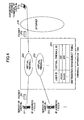
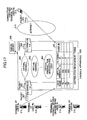
- the distribution management table 201 is referred to by using the source IP address [a.a.a.a] as a search key, and the virtual firewall ID 202 that is associated with the source IP address [a.a.a.a] is retrieved so that the packet 221 is distributed to the virtual firewall 202.
- a PPP connection is established between the user terminal and the network.
- a PPP connection is established between the user terminal and the network.
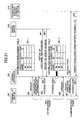
- the firewall apparatus 100 receives a packet 121 that is sent from the user terminal 114 to the connection partner terminal 113, and the firewall apparatus 100 refers to the distribution management table 101 by using [c.c.c.c], as a search key, included in the packet 121 as a source IP address, so that it is determined that the source IP address is not registered.
- the virtual firewall 104 for the unregistered user does not include a filtering rule to unconditionally pass all packets, or includes a filtering rule common for all unregistered users.
- the firewall apparatus 100 exchanges information of NCP with the user terminal 114 in (143), the firewall apparatus 100 sends the user IP address [c.c.c.c] to the user terminal 114, and the user terminal 114 recognizes that the own user IP address is [c.c.c.c].
- the firewall apparatus 100 can discard the packets.
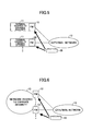
- the embodiment 1-5 of the present invention is described with reference to Figs.8, 15 and 16.
- This embodiment shows a case where a terminal 115 of a firewall-service-unregistered user #d connects to the Internet 110, and, after that, the terminal 115 performs IP communications with a connection partner terminal 113.
- the user #d is a user who should be registered in the firewall service. But, in this case, the user name #d is not correctly registered in the distribution management table 101-5 for the reason that the manager of the firewall apparatus 100 forgot about registering the user name #d in the distribution management table 101-5 or erroneously registered the user name. However, the user name #d and the password are correctly registered in the RADIUS server 130.
- authentication information from the user terminal for network connection can be used so that the user IP address is dynamically associated with the virtual firewall ID so as to apply a filtering rule complying with security policy that the user defines to packets that the user terminal transmits or receives.
- the unregistered user is not registered in the distribution management table, so that transmit/receive packet of the unregistered user is automatically distributed to the virtual firewall for unregistered users.
- the number of entries registered in the distribution management table can be limited to registered users who are currently establishing a network connection, so that search time can be decreased.
- the unregistered user is registered in the distribution management table, and the transmission/receive packet of the unregistered user is distributed to a virtual firewall for unregistered users.
- the packet of the user is discarded.
- the firewall apparatus can discard these packets.
- the firewall apparatus of the embodiment 1-5 when a manager of the firewall apparatus forgets about registering the user name in the distribution management table or erroneously registers the user name, communication that should not be established can be forced to terminate from the viewpoint of security.
- the number of multiple users is large in the constant connection service, the number of sum of filtering rules increases in proportion to the number of multiple users for keeping serviceability for providing independent security policy for each user.
- the security policy of the user #a is written in the filtering table 561 whose filtering ID is ⁇
- the security policy of the user #b is written in the filtering table 562 whose filtering ID is ⁇
- the security policy of the user #d is written in the filtering table 563 whose filtering ID is ⁇ in the virtual firewall 303.
- the reason why the user #a and the user #b are accommodated in the same virtual firewall 302 is that, for example, common filtering policies for the user #a and the user #b are the same, or the virtual firewall is established for each Internet provider and the user #a and the user #b belong to the same Internet provider.
- the user IP address is registered in the distribution management table 301, it cannot be performed to distribute packets from each user to a corresponding virtual firewall and to assign a filtering ID.
- the terminal 311 of the user #a connects to the Internet 310, and after that, the terminal 311 performs IP communications with a connection partner terminal 313.
- the firewall apparatus 300 Based on the exchange of authentication information that is performed after that (840 in Fig.19), the firewall apparatus 300 extracts the user name #a sent from the user terminal 311 so as to hold the user name #a (process point 850 in Fig.19).
- the firewall apparatus 300 sends the user IP address [a. a. a. a] to the user terminal 311 so that the user terminal ascertains that the own user IP address is [a. a. a. a] while exchanging information of NCP (Network Control Protocol) between the user terminal 311 and the firewall apparatus 300.
- NCP Network Control Protocol
- a PPP connection is established between the user terminal 311 and the Internet 320.
- the firewall apparatus of the embodiment 2-2 of the present invention is different from the firewall apparatus in the before-mentioned embodiment 2-1 in that the firewall apparatus of the embodiment 2-2 does not include the virtual firewall.
- a security policy of the user #a is written in the filtering table 561 to which ⁇ is assigned as the filtering ID
- a security policy of the user #b is written in the filtering table 562 to which ⁇ is assigned as the filtering ID.
- NCP After NCP ends, PPP connection is established between the user terminal 311 and the Internet 320.
- firewall apparatus of this embodiment features different from the firewall apparatus of the embodiment 2-1 are mainly described.
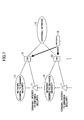
- An outline configuration of the firewall apparatus of this embodiment 2-3 is the same as that shown in Fig.17. Also in this embodiment, it is assumed that the network connection method from the user is PPP and authentication communication is RADIUS.
- the filtering ID of the embodiment 2-1 is divided to an individual filtering ID and a common filtering ID, so that filtering policies specific for each user are included in corresponding individual filtering tables, and a filtering policy that can be commonly used for plural users is included in the common filtering table.
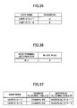
- each of the distribution management table 301 in Fig.17 and the distribution management table (301-1) in Fig.19 is replaced by a distribution management table 601 shown in Fig.22, and the distribution management table (301-2) shown in Fig.19 is replaced by a distribution management table shown in Fig.23.
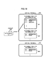
- Fig.24 is a diagram showing a configuration of a filtering table in the virtual firewall in the firewall apparatus of this embodiment.
- Filtering policies specific for each user are written in corresponding individual filtering tables (561, 562, 563), and filtering policies commonly used plural users are written in the common filtering tables (571, 572).
- filtering policies written in a common filtering table 572 to which "II" is assigned as the filtering ID are also applied to the user #d.
- the user IP address that is a user ID of each user terminal is not decided so that it cannot be registered at this time (state of distribution management table 601-1 in Fig.22).
- the user IP address is registered in the distribution management table 601, it cannot be performed to distribute packets from each user to a corresponding virtual firewall and to assign an individual filtering ID and a common filtering ID.
- NCP After NCP ends, PPP connection is established between the user terminal 311 and the Internet 320.
- a passing or discarding process is applied to the packet 322 according to a filtering rule complying with the security policy of the user #a written in the individual filtering table 561 having ⁇ as the filtering ID.
- the passing or discarding process is applied to the packet 324 according to a filtering rule complying with the security policy of the user #a written in the individual filtering table 561 having ⁇ as the filtering ID.
- the passing or discarding process is performed for the packet according to the filtering policy written in the common filtering table 571 to which I is assigned as the common filtering ID.
- the individual filtering table and the common filtering table in this embodiment can be introduced.
- the distribution management table is provided with the individual filtering ID and the common filtering ID similar to those of this embodiment instead of the filtering ID, and is provided with the individual filtering table and the common filtering table similar to those of this embodiment instead of the filtering table.
- This embodiment of the firewall apparatus is an embodiment in which, in the firewall apparatus of the embodiments 2-1 or 2-2, the combination of the user name and the password sent by the report of the user name and the password is not the same as the combination of the user name and the password registered in the RADIUS server 330 for the reason that the user name or the password sent from the user #a is not correct, for example.
- Fig.25 is a sequence chart showing the operations of the firewall apparatus of the embodiment 2-4.
- This embodiment of the firewall apparatus is an embodiment in which, in the firewall apparatus of the embodiment 2-1, a terminal 314 of a firewall-service-unregistered user #c connects to the Internet 310, and, after that, the terminal 314 performs IP communications with a connection partner terminal 313.
- FIG. 2-5 An outline configuration of the firewall apparatus of this embodiment 2-5 is the same as that of Fig.17, and Fig.26 is a diagram showing information of the distribution management table of this embodiment.
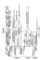
- Fig.27 is a sequence diagram showing the operations of the firewall apparatus of this embodiment.
- the firewall apparatus 300 searches the distribution management table (301-3) for the user name #c. But, since the user name #c does not exist, the firewall apparatus does not register the user IP address [c.c.c.c] in the distribution management table (301-3).
- the firewall apparatus 300 exchanges information of NCP with the user terminal 314 in (343 in Fig.27), the firewall apparatus 300 sends the user IP address [c.c.c.c] to the user terminal 314, and the user terminal 314 ascertains that the own user IP address is [c.c.c.c].
- a PPP connection is established between the user terminal and the network.
- the firewall apparatus 300 receives a packet 321 that is sent from the user terminal 314 to the connection partner terminal 313, the firewall apparatus 300 searches the distribution management table (301-3) by using [c.c.c.c] as a search key, included in the packet 321 as a source IP address, so that it is determined that the source IP address is not registered.
- the packet 323 sent from the communication partner terminal 313 when it is determined that the destination IP address is not registered as a result of searching of the distribution management table (301-3) by using the destination user IP address [c.c.c.c] as a search key, the packet 323 is distributed to a virtual firewall 304 for unregistered users (process point 353 in Fig.27).
- the firewall apparatus of this embodiment can be applied to the before-mentioned embodiment 2-2.
- a packet from the terminal 314 of the firewall service-unregistered user #c and a packet to the terminal 314 of the firewall service-unregistered user #c pass through an alternative route 305 shown in Fig.20
- This embodiment of the firewall apparatus is an embodiment in which, conditions are the same as those of the firewall apparatus in the embodiment 2-5, wherein the terminal 314 of the firewall-service-unregistered user #c connects to the Internet 310, and, after that, the terminal 314 performs IP communications with the connection partner terminal 313.
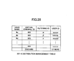
- FIG.17 An outline configuration of the firewall apparatus of this embodiment is the same as that of Fig.17, and Fig.28 is a diagram showing information of the distribution management table of this embodiment.
- the firewall-service-unregistered user #c the user name and the virtual firewall are not registered in the distribution management table 301-4. But, the user #c receives a communication service to the Internet 310 via the terminal 314, and the user name and the password are registered in the RADIUS server 330.
- the firewall apparatus 300 When the firewall apparatus 300 receives the report (342 in Fig.29) of the user IP address, the firewall apparatus 300 holds a user IP address [c.c.c.c], included in the notification of the user IP address, to be provided to the user terminal.
- the firewall apparatus 300 searches the distribution management table (301-4) for the user name #c. But, the user name #c does not exist.
- the firewall apparatus 300 sends the user IP address [c.c.c.c] to the user terminal 314, and the user terminal 314 ascertains that the own user IP address is [c.c.c.c].
- a PPP connection is established between the user terminal and the network.
- the virtual firewall 304 for the unregistered user does not include a filtering rule so as to unconditionally pass all packets, or includes a filtering rule common for all unregistered users.
- the packet is discarded as shown in the last line of the distribution management table 301-4 in Fig.28.
- the firewall apparatus 300 can discard the packet.
- the user IP address [c. c. c. c] and the filtering ID for the unregistered users are registered in the distribution table (301-4). Then, a packet from the terminal 314 of the firewall service-unregistered user #c and a packet to the terminal 314 of the firewall service-unregistered user #c pass through an alternative route 305 shown in Fig.20.
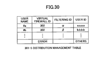
- This embodiment of the firewall apparatus is an embodiment in which, as in the embodiment 2-1, the terminal 315 of the firewall-service-unregistered user #d connects to the Internet 310, and, after that, the terminal 315 performs IP communications with the connection partner terminal 313.
- FIG.30 is a diagram showing information of the distribution management table of this embodiment.
- Fig.31 is a sequence chart showing the operations of the firewall apparatus of this embodiment.
- the firewall apparatus 300 When the firewall apparatus 300 receives the report (342 in Fig.31) of the user IP address, the firewall apparatus 300 holds the user IP address [d. d. d. d], included in the report 342 of the user IP address, to be provided to the user terminal.
- the firewall apparatus of this embodiment can be also applied to the before-mentioned embodiment 2-2.
- the user terminal side IP address to be registered on the filtering table 1961 in Fig.32 needs to be dynamically set for each PPP connection, and the setting process amount increases in proportion to the number of rules.
- an individual filtering ID is assigned to a packet in the distributing management table 2001, and the individual filtering ID instead of the user terminal side IP address is used in the individual filtering table 2061.
- the individual filtering ID is a fixed value irrespective of a value of the user terminal side IP address, there is no effect on the individual filtering table 2061 however repeatedly PPP connection is performed.
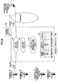
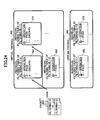
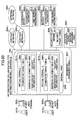
- the authentication collaboration type distribution firewall apparatus (to be simply referred to as "firewall apparatus" hereinafter) 501 accommodates a user terminal (502-1) used by a user (515-1) and a user terminal (502-2) used by a user (515-2) wherein each terminal starts communication by authentication, and the firewall apparatus is connected to an external network (the Internet, for example) 503.
- an external network the Internet, for example
- the firewall apparatus 501 is connected to a security policy server 504 that includes a security policy table 511 holding security policies specific for users, and is connected to an identifier management server 505 that includes an identifier management table 512 holding identifiers to be distributed to the firewall apparatus 501.
- a RADIUS (Remote Authentication Dial-in User Service) server for example, can be used as the authentication server.
- an IP address to be provided to a user terminal can be used as the user terminal information stored in the user terminal information part 514.
- the firewall apparatus 501 includes a distribution management table 507 for associating user terminal information included in a received packet with an identifier that indicates a filtering table for filtering the received packet, and a firewall part 508 that actually performs filtering.
- the firewall part 508 includes a common filtering table 509 holding security policies common to the user (515-1) and the user (515-2), and an individual filtering table area for holding an individual security policy of the user (515-1) or the user (515-2).
- the individual filtering table area is divided to an area in which identification information is written, and an area, associated with the area in which identification information are written, in which security policy is written.
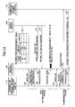
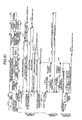
- Figs.40 and 41 show one example of a sequence of operations of the network model shown in Fig.34, and Figs.40 and 41 show a sequence in which, after the user (515-1) connects to the external network 503, the user (515-1) disconnects; after that, the user (515-2) connects to the external network 503, and after that, the user (515-2) disconnects.
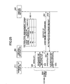
- connection start sequence of the user (515-1) is described.
- the user (515-1) sends a user name (user 515-1) and a password ( ⁇ ) to the firewall apparatus 501 using the user terminal (11-1, 11-2 in Fig.40).
- the authentication server 506 retrieves authentication information 513 using the received user name (user 515-1) and the password ( ⁇ ) so as to determine that authentication is possible (11-5 in Fig.40).
- the authentication server 506 extracts, from the pool table of the user terminal information part 514, usable user terminal information (IP_1) in which the in-use flag is "0", changes the extracted in-use flag to "1", and reports the extracted user terminal information (IP_1) to the firewall apparatus 501 with an authentication approval report (11-6, 11-7 in Fig.40).
- the identifier management server 505 searches the identifier management table 512 based on the received user name (user 515-2) so as to extract a common filtering table ID (common 509) and an individual filtering table ID (individual 510-1) that are associated with the user name, and sends the identifiers (common 509, individual 510-1) to the firewall apparatus 501 (11-10, 11-11 in Fig.40).
- the firewall apparatus 501 holds the received individual filtering table ID (individual 510-1), and writes the received common filtering table ID (common 509), the individual filtering table ID (individual 510-1) and the holding user terminal information (IP_1) into the distribution management table 507 shown in Fig.39 (11-12 in Fig.40).
- the firewall apparatus 501 sends the holding user name (user 515-1) to the security policy server 504 (11-13 in Fig.40).
- the security policy server 504 searches the holding security policy table 512 based on the received user name (user 515-1) so as to extract individual security policies (rule 1-1 ⁇ rule 1-m) associated with the user name (11-4 in Fig.40) and sends them to the firewall apparatus 501 (11-15 in Fig.40).
- the firewall apparatus 501 writes the holding individual filtering table ID (individual 510-1) into the identification information of the individual filtering table area 510, and writes the received individual security policies (rule 1-1 ⁇ rule 1-m) into the security policy area (11-16 in Fig.40).
- connection start sequence ends, so that the user (515-1) can connect to the external network 503 via the user terminal (502-1).
- the user terminal (502-1) transfers a packet to the external network 503, the user terminal (502-1) determines its own address as the user terminal information (IP_1) finally received in the connection start sequence, and adds the address to a packet to transfer the packet to the firewall apparatus 501 (11-18 in Fig.40).
- IP_1 user terminal information
- the firewall apparatus 501 extracts the user terminal information (IP_1) from the received packet, searches the distribution management table 507 using the user terminal information (IP_1) as a key so as to extract the common filtering table ID (common 509) and the individual filtering table ID (individual 510-1) (11-19 in Fig.40).
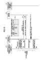
- the firewall apparatus 501 receives a packet for the user terminal (502-1) from the external network 503 (11-23 in Fig.40) and transfers the packet to the user terminal (502-1), since the packet received from the external network 503 includes the user terminal information (IP_1) as a destination address, the firewall apparatus 501 extracts the user terminal information (IP_1) from the received packet (11-24 in Fig.40). Then, the firewall apparatus 501 transfers the packet to the user terminal (502-1) (11-27 in Fig.40) after filtering the packet according to a sequence the same as that for transferring a packet from the user terminal (502-1) to the external network 503 (11-25, 11-26 in Fig.40).
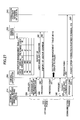
- a disconnection request is reported to the firewall apparatus 501 (11-28, 11-29 in Fig.40) from the user (515-1) via the user terminal (502-1).
- the firewall apparatus 501 When the firewall apparatus 501 receives the disconnection request, the firewall apparatus 501 checks a line via which the request is received, and derives the user terminal information (IP-1) associated with the line in the connection start sequence.
- IP-1 user terminal information
- the firewall apparatus 501 Based on the user terminal information, the firewall apparatus 501 extracts the individual filtering table ID (individual 510-1) from an entry associated with the user terminal information (IP-1) in the distribution management table 507, and deletes the entry (11-30 in Fig.40).
- the firewall apparatus 501 sends the derived user terminal information (IP-1) to the authentication server 506 (11-32 in Fig.40).
- the authentication server 5-6 restores, to "0", the in-use flag in an entry associated with the received user terminal information in the pool table in the user terminal information part 514 (11-33 in Fig.40).
- connection start sequence a connection start sequence, a communication sequence and a disconnection sequence are performed for the user (515-2) in the same way for the user (515-1) (11-34 ⁇ 11-66 in Fig.41).
- Characteristics of sequences for the user (515-2) are as follows. Since the disconnection sequence is performed for the user (515-1), information on the user (515-1) does not exist in the distribution management table 507 and in the individual filtering table area 510 in the firewall apparatus 501. Thus, information on user (515-2) can be written into the same areas, and the user terminal information (IP_1) used by the user terminal (515-1) can be used, so that filtering can be performed by using the security policy for the user (515-2) even though the user terminal information for the user (515-2) is the same as the user terminal information (IP_1) for the user (515-2).
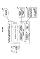
- Fig.42 is a block diagram showing an outline configuration of a firewall apparatus of the embodiment 3-2 of the present invention, and a network model in which the firewall apparatus of the embodiment 3-2 of the present invention is used.
- the user (515-1) can connect to the firewall apparatus 1201, and the firewall apparatus 1201 is connected to the external network 503, the security policy server 504, the identifier management server 505 and the authentication server 506.
- the firewall part 1208 includes a common filtering table 1209 holding security policies common to plural users including the user (515-1) and an individual filtering table area 1210 for holding individual security policies of the user (515-1).
- the individual filtering table area 1210 is divided to an area in which identification information is written, and an area in which security policies are written.
- Fig.43 is a diagram showing an example of a sequence of operations in the network model in Fig.42.
- Fig.43 shows a sequence in which, after the sequence shown in Fig.40 is performed, the user (515-1) connects to the external network 503 again from the user terminal 1202 connected to the firewall apparatus 1201, performs communications and disconnects.
- connection sequence in which the user (515-1) moves to the user terminal 1202 to perform re-connection, a sequence for performing communication and a sequence for disconnection, shown in 12-1 ⁇ 12-33 in Fig.43, are the same as the sequences performed using the firewall apparatus 501 shown in Fig.40. Thus, the description is not provided.
- security policies corresponding to a user can be applied even though the user changes the firewall apparatus that accommodates the user.
- Fig.44 is a block diagram showing an outline configuration of a firewall apparatus of the embodiment 3-3 of the present invention, and a network model in which the firewall apparatus of the embodiment 3-3 of the present invention is used.
- firewall apparatus 501 holds, in its inside, the identifier management table 512 associating user names with various identifiers held in the identifier management server 505.
- Fig.45 is a diagram showing an example of a sequence showing operations of the network model shown in Fig.44.
- the sequence is different from the sequence shown in Fig.40 in that communication with the identifier management server 505 is deleted, and a sequence for the identifier management table 512 held in the inside of the firewall apparatus 501 is newly added.
- the firewall apparatus 501 holds user information received from the authentication server 506 in 11-8 in Fig.45, and associates a connection line of the user terminal (502-1) with the user information. After that, the firewall apparatus 501 searches the identifier management table 512 using the user name held in 11-3 in Fig.45 as a search key to extract the common filtering table ID and the individual filtering table ID (15-19, 15-10, 15-11 in Fig.45).
- the firewall apparatus 501 since the firewall apparatus 501 needs to hold the identifier management table 512 including various identifiers for all users who may be accommodated, more memory capacity of the firewall apparatus 501 becomes necessary or the number of the users that can be accommodated decreases. However, operations can be performed without performing communication with the identifier management server.
- Fig.47 is a diagram showing an example of a sequence showing operations of the network model shown in Fig.46.
- the sequence is different from the sequence shown in Fig.40 in that communication with the security policy server 504 is deleted, and a sequence for the security policy table 511 held in the inside of the firewall apparatus 501 is newly added.
- the firewall apparatus 501 searches the security policy table 511 using the user name held in 11-3 in Fig.47 as a search key to extract security policies corresponding to the user name (17-13, 17-14, 17-15 in Fig.47).
- the firewall apparatus 501 since the firewall apparatus 501 needs to hold the security policy table 511 including individual security policies for all users who may be accommodated, more memory capacity of the firewall apparatus becomes necessary or the number of the users that may be accommodated decreased. However, operations can be performed without performing communication with the security policy server.
- Fig.48 is a block diagram showing an outline configuration of a firewall apparatus of the embodiment 3-5 of the present invention, and a network model in which the firewall apparatus of the embodiment 3-5 of the present invention is used.
- firewall apparatus 501 holds, in its inside, the security policy table 511 associating user names with various individual security policies held in the security policy server 504 and the identifier management table 512 associating user names with various identifies held in the identifier management server 505.
- Fig.49 is a diagram showing an example of a sequence showing operations of the network model shown in Fig.48.
- the sequence is different from the sequence shown in Fig.40 in that communication parts with the security policy server 504 and communication parts with the identifier management server 505 are deleted, and a sequence for the security policy table 511 and a sequence for the identifier management table 512 held in the inside of the firewall apparatus 501 are newly added.
- the firewall apparatus 501 In sequences changed from the sequence in Fig.40, after the firewall apparatus 501 holds user information received from the authentication server 506, and associates a connection line of the user terminal (502-1) with the user information in 11-8 in Fig.49, the firewall apparatus 501 searches the identifier management table 512 using the user name held in 11-3 in Fig.49 as a search key to extract the common filtering table ID and the individual filtering table ID (19-9, 19-10, 19-11 in Fig.49).
- the firewall apparatus 501 since the firewall apparatus 501 needs to hold the security policy table 511 including individual security policies for all users who may be accommodated, more memory capacity of the firewall apparatus becomes necessary or the number of the users that can be accommodated further decreases, and since the firewall apparatus 501 needs to hold the identifier management table 512 including various identifies for all users who may be accommodated, more memory capacity of the firewall apparatus becomes necessary or the number of the users that can be accommodated further decreases.
- operations can be performed without performing communications with the security policy server and the identifier management server.
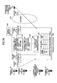
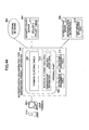
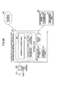
- Fig.50 is a block diagram showing an outline configuration of a firewall apparatus of the embodiment 3-6 of the present invention, and a network model in which the firewall apparatus of the embodiment 3-6 of the present invention is used.
- the firewall apparatus 2001 accommodates a user terminal (2002-1), used by a user (2015-1), that starts to connect to an external network 2003 via a contract network 1 (ISP : Internet Service Provider, for example) (2016-1) by authentication, and a user terminal (2002-2), used by a user (2015-2), that starts to connect to the external network 2003 via a contract network 2 (2016-2) by authentication.
- ISP Internet Service Provider
- the firewall apparatus 2001 is connected to a security policy server 2004 that includes a security policy table 2011 holding security policies specific for users, and connected to an identifier management server 2005 that includes an identifier management table 2012 holding identifiers to be distributed to the firewall apparatus 2001.
- the firewall apparatus 2001 is connected to an authentication server 1 (2006-1) that includes authentication information (2013-1) of users, and a user terminal information part (2014-1) holding a pool table including user terminal information to be provided to a user terminal when performing authentication, wherein the authentication server 1 authenticates a user to connect to an external network via the contract network 1.
- an authentication server 1 2006-1 that includes authentication information (2013-1) of users, and a user terminal information part (2014-1) holding a pool table including user terminal information to be provided to a user terminal when performing authentication, wherein the authentication server 1 authenticates a user to connect to an external network via the contract network 1.
- the firewall apparatus 2001 includes a distribution management table 2007 for linking user terminal information attached to a received packet, virtual firewalls (2014-1, 2014-2) for filtering the received packet and an identifier to indicate a filtering table with each other.
- the virtual firewall 1 (2014-1) includes a common filtering table (2009-1) holding security policies common to plural users for performing filtering by the virtual firewall 1 (2014-1), and an individual filtering table area (2010-1) for holding individual security policies for each user.
- the individual filtering table area (2010-1) is divided into an area in which identification information is written, and an area, associated with the area in which identification information is written, in which security policy is written.
- the virtual firewall 2 (2014-2) also includes a common filtering table (2009-2) and an individual filtering table area (2010-2), where the individual filtering table area (2010-2) is divided into an area in which identification information is written, and an area associated with the area in which identification information is written, in which security policy is written.
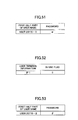
- Fig.51 is a diagram showing details of the authentication information (2013-1) in the authentication server 1 shown in Fig.50.
- Fig.52 is a diagram showing details of the pool table held in the user terminal information part (2014-1) in the authentication server 1 shown in Fig.50.
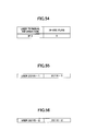
- Fig.55 is a diagram showing a user name sent to the firewall apparatus 2001 via the user terminal (2002-1) by the user (2015-1)
- Fig.56 is a diagram showing a user name sent to the firewall apparatus 2001 via the user terminal (2002-2) by the user (2015-2).
- Fig.57 is a diagram showing details of the identifier management table 2012 in the identifier management server shown in Fig.50
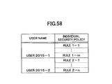
- Fig.58 is a diagram showing details of the security policy table 2011 in the security policy server shown in Fig.50.
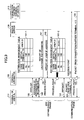
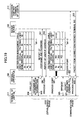
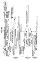
- Figs.59 and 60 show one example of a sequence of operations of the network model shown in Fig.50
- Figs. 59 and 60 show a sequence in which, after the user (2015-1) connects to the external network 2003 via the contract network 1 (2016-1), the user (2015-1) disconnects, and, a sequence in which, after the user (2015-2) connects to the external network 2003 via the contract network 2 (2016-2), the user (2015-2) disconnects.
- the firewall apparatus 2001 that receives the user name (user 2015-1_2016-1) and the password ( ⁇ ) holds a first half part of the user name (user 2015-1), and determines to send authentication information to the authentication server 1 (2006-1) based on a second half part of the user name so as to send the first half part of the user name (user 2015-1) and the password ( ⁇ ) (21-4 in Fig.59).
- the authentication server 1 retrieves authentication information (2013-1) using the received first half part of the user name (user 2015-1) and the password ( ⁇ ) so as to determine that authentication is possible (21-5 in Fig.59).
- the authentication server 1 extracts, from the pool table of the user terminal information part (2014-1), usable user terminal information (IP_1) in which the in-use flag is "0" (21-6 in Fig.59), changes the extracted in-use flag to "1", and reports the extracted user terminal information (IP_1) to the firewall apparatus 2001 with an authentication approval notification (21-7 in Fig.59).
- the firewall apparatus 2001 holds the received user terminal information (IP_1) (21-8 in Fig.59), and associates the user terminal information (IP_1) with a line to which the user terminal (2002-1) connects, and sends the held first half part of the user name (user 2015-1) to the identifier management server 2005 (21-9 in Fig.59).
- the identifier management server 2005 searches the identifier management table 2012 based on the received first half part (user 2015-1) of the user name so as to extract a virtual firewall ID (virtual 2014-1), a common filtering table ID (common 2009-1), and an individual filtering table ID (individual 2010-1) that are associated with the half part (user 2015-2) of the user name, and sends the identifiers to the firewall apparatus 2001 (21-11 in Fig.59).
- a virtual firewall ID virtual 2014-1
- common 2009-1 common 2009-1
- individual filtering table ID individual filtering table ID
- the firewall apparatus 2001 holds the received individual filtering table ID (individual 2010-1), and writes the received virtual firewall ID (virtual 2014-1), the common filtering table ID (common 2009-1), the individual filtering table ID (individual 2010-1) and the holding user terminal information (IP_1) into the distribution management table 2007 (21-12 in Fig.59).
- the firewall apparatus 2001 sends the holding first half part (user 2015-1) of the user name to the security policy server 2004 (21-13 in Fig.59).
- the firewall apparatus 2001 writes the holding individual filtering table ID (individual 2010-1) into the identification information area of the individual filtering table area (2010-1), and writes the received individual security policies into the security policy area (21-16 in Fig.59).
- the firewall apparatus 2001 After performing this series of processes, the firewall apparatus 2001 sends an authentication success report including the holding user terminal information (IP_1) to the user terminal (2002-1) (21-17 in Fig.59).
- connection start sequence ends, so that the user (2015-1) can connect to the external network 2003 via the user terminal (2002-1).
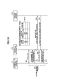
- the user terminal (2002-1) When the user terminal (2002-1) transfers a packet to the external network 2003, the user terminal (2002-1) determines its own address as the user terminal information (IP_1) finally received in the connection start sequence, and adds the address to a packet to transfer the packet to the firewall apparatus 2001 (21-18 in Fig.59).
- IP_1 user terminal information
- the firewall apparatus 2001 extracts the user terminal information (IP_1) from the received packet, searches the distribution management table 2007 using the user terminal information (IP_1) as a key so as to extract the virtual firewall ID (virtual 2014-1), the common filtering table ID (common 2009-1), and the individual filtering table ID (individual 2010-1) (21-19 in Fig.59).
- the firewall apparatus 2001 distributes the received packet to the virtual firewall (2014-1) indicated by the extracted virtual firewall ID (virtual 2014-1), and performs packet filtering using filtering tables indicated by the extracted common filtering table ID (common 2009-1) and the individual filtering table ID (individual 2010-1) in the virtual firewall (2014-1) indicated by the extracted virtual firewall ID (virtual 2014-1) (21-20, 21-21 in Fig.59).
- the packet is transferred to the external network 2003 via the contract network 1 (2016-1) (21-22 in Fig.59).
- the firewall apparatus 2001 receives a packet for the user terminal (2002-1) from the external network 2003 via the contract network 1 (2016-1) (21-23 in Fig.59) and transfers the packet to the user terminal (2002-1), since the packet received from the external network 2003 includes the user terminal information (IP_1) as a destination address, the firewall apparatus 2001 extracts the user terminal information (IP_1) from the received packet (21-24 in Fig.59). Then, the firewall apparatus 2001 transfers the packet to the user terminal (2002-1) (21-27 in Fig.59) after filtering the packet according to a sequence the same as that for transferring a packet from the user terminal (2002-1) to the external network 2003 (21-25, 21-26 in Fig.59).
Landscapes
- Engineering & Computer Science (AREA)
- Computer Hardware Design (AREA)
- Computer Security & Cryptography (AREA)
- Computing Systems (AREA)
- General Engineering & Computer Science (AREA)
- Computer Networks & Wireless Communication (AREA)
- Signal Processing (AREA)
- Data Exchanges In Wide-Area Networks (AREA)
- Computer And Data Communications (AREA)
Applications Claiming Priority (7)
| Application Number | Priority Date | Filing Date | Title |
|---|---|---|---|
| JP2003027828 | 2003-02-05 | ||
| JP2003027828 | 2003-02-05 | ||
| JP2003044770 | 2003-02-21 | ||
| JP2003044770 | 2003-02-21 | ||
| JP2003045222 | 2003-02-24 | ||
| JP2003045222 | 2003-02-24 | ||
| PCT/JP2004/001124 WO2004071038A1 (ja) | 2003-02-05 | 2004-02-04 | ファイアウォール装置 |
Publications (2)
| Publication Number | Publication Date |
|---|---|
| EP1592189A1 true EP1592189A1 (de) | 2005-11-02 |
| EP1592189A4 EP1592189A4 (de) | 2012-05-23 |
Family
ID=32854102
Family Applications (1)
| Application Number | Title | Priority Date | Filing Date |
|---|---|---|---|
| EP04708074A Withdrawn EP1592189A4 (de) | 2003-02-05 | 2004-02-04 | Firewall-einrichtung |
Country Status (4)
| Country | Link |
|---|---|
| US (1) | US7735129B2 (de) |
| EP (1) | EP1592189A4 (de) |
| JP (1) | JP3852017B2 (de) |
| WO (1) | WO2004071038A1 (de) |
Cited By (4)
| Publication number | Priority date | Publication date | Assignee | Title |
|---|---|---|---|---|
| US7904954B2 (en) | 2005-11-30 | 2011-03-08 | Huawei Technologies Co., Ltd. | Method, device and security control system for controlling communication border security |
| EP2575313A1 (de) * | 2011-09-27 | 2013-04-03 | NorCom Information Technology AG | Morphing-Firewall |
| RU2552135C2 (ru) * | 2013-09-09 | 2015-06-10 | Общество с ограниченной ответственностью "СмартТелеМакс" | Устройство защиты от атак для сетевых систем |
| CN105187378A (zh) * | 2006-01-13 | 2015-12-23 | 飞塔公司 | 处理网络流量的计算机系统及方法 |
Families Citing this family (36)
| Publication number | Priority date | Publication date | Assignee | Title |
|---|---|---|---|---|
| US7475424B2 (en) * | 2004-09-02 | 2009-01-06 | International Business Machines Corporation | System and method for on-demand dynamic control of security policies/rules by a client computing device |
| US7917944B2 (en) | 2004-12-13 | 2011-03-29 | Alcatel Lucent | Secure authentication advertisement protocol |
| CN101128805B (zh) * | 2005-02-24 | 2010-05-12 | 富士通株式会社 | 连接支持装置及网关装置 |
| JP4545085B2 (ja) * | 2005-12-08 | 2010-09-15 | 富士通株式会社 | ファイアウォール装置 |
| US8024787B2 (en) * | 2006-05-02 | 2011-09-20 | Cisco Technology, Inc. | Packet firewalls of particular use in packet switching devices |
| US8151337B2 (en) * | 2006-06-30 | 2012-04-03 | Microsoft Corporation | Applying firewalls to virtualized environments |
| US8055760B1 (en) * | 2006-12-18 | 2011-11-08 | Sprint Communications Company L.P. | Firewall doctor |
| US8127347B2 (en) * | 2006-12-29 | 2012-02-28 | 02Micro International Limited | Virtual firewall |
| FR2915598A1 (fr) * | 2007-04-27 | 2008-10-31 | France Telecom | Procede de filtrage de flots indesirables en provenance d'un terminal presume malveillant |
| US8635686B2 (en) * | 2007-05-25 | 2014-01-21 | Apple Inc. | Integrated privilege separation and network interception |
| US7853992B2 (en) * | 2007-05-31 | 2010-12-14 | Microsoft Corporation | Configuring security mechanisms utilizing a trust system |
| US8984620B2 (en) * | 2007-07-06 | 2015-03-17 | Cyberoam Technologies Pvt. Ltd. | Identity and policy-based network security and management system and method |
| US20140201017A1 (en) | 2008-06-19 | 2014-07-17 | Servicemesh, Inc. | Systems and methods for providing repeated use of computing resources |
| US9069599B2 (en) * | 2008-06-19 | 2015-06-30 | Servicemesh, Inc. | System and method for a cloud computing abstraction layer with security zone facilities |
| KR101018435B1 (ko) * | 2008-08-14 | 2011-02-28 | 한국전자통신연구원 | 사용자 단말기의 보안 관리 장치 및 방법 |
| US20110131648A1 (en) * | 2009-11-30 | 2011-06-02 | Iwebgate Technology Limited | Method and System for Digital Communication Security Using Computer Systems |
| US9531670B2 (en) * | 2009-11-30 | 2016-12-27 | Iwebgate Technology Limited | System and method for network virtualization and security using computer systems and software |
| FR2958478B1 (fr) * | 2010-04-02 | 2012-05-04 | Sergio Loureiro | Procede de securisation de donnees et/ou des applications dans une architecture informatique en nuage |
| CN101888374B (zh) * | 2010-05-19 | 2013-06-26 | 山东中创软件商用中间件股份有限公司 | 基于内嵌的对响应内容进行缓存过滤的方法、装置及系统 |
| US8904511B1 (en) * | 2010-08-23 | 2014-12-02 | Amazon Technologies, Inc. | Virtual firewalls for multi-tenant distributed services |
| JP2012070225A (ja) * | 2010-09-24 | 2012-04-05 | Hitachi Cable Ltd | ネットワーク中継装置及び転送制御システム |
| JP5824911B2 (ja) | 2011-06-29 | 2015-12-02 | 富士通株式会社 | 情報処理装置、情報処理プログラムおよび管理方法 |
| US8763106B2 (en) * | 2011-09-08 | 2014-06-24 | Mcafee, Inc. | Application state sharing in a firewall cluster |
| US8887263B2 (en) * | 2011-09-08 | 2014-11-11 | Mcafee, Inc. | Authentication sharing in a firewall cluster |
| US9100366B2 (en) * | 2012-09-13 | 2015-08-04 | Cisco Technology, Inc. | Early policy evaluation of multiphase attributes in high-performance firewalls |
| CN103973673B (zh) * | 2014-04-09 | 2017-11-03 | 汉柏科技有限公司 | 划分虚拟防火墙的方法和设备 |
| US9497165B2 (en) * | 2015-03-26 | 2016-11-15 | International Business Machines Corporation | Virtual firewall load balancer |
| US9641485B1 (en) * | 2015-06-30 | 2017-05-02 | PacketViper LLC | System and method for out-of-band network firewall |
| US10051075B1 (en) * | 2015-09-09 | 2018-08-14 | Google Llc | Systems and methods for maintaining an asynchronous communication via an intermediary |
| KR102333028B1 (ko) * | 2017-10-19 | 2021-11-29 | 삼성에스디에스 주식회사 | 방화벽 정책 제어 장치 및 방법 |
| US10728218B2 (en) * | 2018-02-26 | 2020-07-28 | Mcafee, Llc | Gateway with access checkpoint |
| KR102667260B1 (ko) | 2018-09-19 | 2024-05-21 | 삼성전자주식회사 | 패킷을 필터링하는 전자 장치 및 그 작동 방법 |
| US11343228B2 (en) * | 2020-05-13 | 2022-05-24 | Arbor Networks, Inc. | Automatically configuring clustered network services |
| US20230283640A1 (en) * | 2022-03-07 | 2023-09-07 | Recolabs Ltd. | Systems and methods for assigning security policies to files and/or records |
| US12506732B2 (en) * | 2022-09-16 | 2025-12-23 | Cisco Technology, Inc. | System, method, and computer-readable storage media for authenticating an endpoint device |
| CN116032575B (zh) * | 2022-12-16 | 2025-08-12 | 北京青云科技集团股份有限公司 | 一种改变防火墙实例容量的方法、装置、设备及存储介质 |
Family Cites Families (16)
| Publication number | Priority date | Publication date | Assignee | Title |
|---|---|---|---|---|
| US6408336B1 (en) * | 1997-03-10 | 2002-06-18 | David S. Schneider | Distributed administration of access to information |
| US7272625B1 (en) * | 1997-03-10 | 2007-09-18 | Sonicwall, Inc. | Generalized policy server |
| US6442588B1 (en) * | 1998-08-20 | 2002-08-27 | At&T Corp. | Method of administering a dynamic filtering firewall |
| US6615357B1 (en) * | 1999-01-29 | 2003-09-02 | International Business Machines Corporation | System and method for network address translation integration with IP security |
| US6678827B1 (en) * | 1999-05-06 | 2004-01-13 | Watchguard Technologies, Inc. | Managing multiple network security devices from a manager device |
| US6463474B1 (en) * | 1999-07-02 | 2002-10-08 | Cisco Technology, Inc. | Local authentication of a client at a network device |
| US7181766B2 (en) * | 2000-04-12 | 2007-02-20 | Corente, Inc. | Methods and system for providing network services using at least one processor interfacing a base network |
| JP2001298449A (ja) | 2000-04-12 | 2001-10-26 | Matsushita Electric Ind Co Ltd | セキュリティ通信方法、通信システム及びその装置 |
| US6931437B2 (en) * | 2000-04-27 | 2005-08-16 | Nippon Telegraph And Telephone Corporation | Concentrated system for controlling network interconnections |
| DK1297446T3 (da) | 2000-07-05 | 2006-01-30 | Ernst & Young Llp | Fremgangsmåde og apparat for tilvejebringelse af computertjenester |
| JP3566198B2 (ja) * | 2000-09-13 | 2004-09-15 | 日本電信電話株式会社 | 仮想プライベートネットワーク間通信における接続管理方法及びその装置 |
| US7093280B2 (en) * | 2001-03-30 | 2006-08-15 | Juniper Networks, Inc. | Internet security system |
| US7170857B2 (en) * | 2001-08-10 | 2007-01-30 | Strix Systems, Inc. | Virtual linking using a wireless device |
| US7313606B2 (en) * | 2001-11-27 | 2007-12-25 | The Directv Group, Inc. | System and method for automatic configuration of a bi-directional IP communication device |
| JP3776821B2 (ja) * | 2002-03-28 | 2006-05-17 | 富士通株式会社 | アドレスアクセスシステム及び方法 |
| DE60202863T2 (de) * | 2002-08-30 | 2005-06-30 | Errikos Pitsos | Verfahren, Gateway und System zur Datenübertragung zwischen einer Netzwerkvorrichtung in einem öffentlichen Netzwerk und einer Netzwerkvorrichtung in einem privaten Netzwerk |
-
2004
- 2004-02-04 JP JP2005504855A patent/JP3852017B2/ja not_active Expired - Fee Related
- 2004-02-04 WO PCT/JP2004/001124 patent/WO2004071038A1/ja not_active Ceased
- 2004-02-04 US US10/544,483 patent/US7735129B2/en not_active Expired - Fee Related
- 2004-02-04 EP EP04708074A patent/EP1592189A4/de not_active Withdrawn
Cited By (4)
| Publication number | Priority date | Publication date | Assignee | Title |
|---|---|---|---|---|
| US7904954B2 (en) | 2005-11-30 | 2011-03-08 | Huawei Technologies Co., Ltd. | Method, device and security control system for controlling communication border security |
| CN105187378A (zh) * | 2006-01-13 | 2015-12-23 | 飞塔公司 | 处理网络流量的计算机系统及方法 |
| EP2575313A1 (de) * | 2011-09-27 | 2013-04-03 | NorCom Information Technology AG | Morphing-Firewall |
| RU2552135C2 (ru) * | 2013-09-09 | 2015-06-10 | Общество с ограниченной ответственностью "СмартТелеМакс" | Устройство защиты от атак для сетевых систем |
Also Published As
| Publication number | Publication date |
|---|---|
| EP1592189A4 (de) | 2012-05-23 |
| WO2004071038A1 (ja) | 2004-08-19 |
| JP3852017B2 (ja) | 2006-11-29 |
| US20060143699A1 (en) | 2006-06-29 |
| US7735129B2 (en) | 2010-06-08 |
| JPWO2004071038A1 (ja) | 2006-06-01 |
Similar Documents
| Publication | Publication Date | Title |
|---|---|---|
| EP1592189A1 (de) | Firewall-einrichtung | |
| JP4541848B2 (ja) | ユーザ端末接続制御方法および装置 | |
| JP4376711B2 (ja) | アクセス管理方法及びその装置 | |
| CN100521650C (zh) | 包转发装置以及接入网系统 | |
| US6907470B2 (en) | Communication apparatus for routing or discarding a packet sent from a user terminal | |
| US8488569B2 (en) | Communication device | |
| JP4909875B2 (ja) | パケット中継装置 | |
| JP2001356973A (ja) | ネットワークシステム | |
| US20030079144A1 (en) | Service control network, server, network device, service information distribution method, and service information distribution program | |
| US20090187646A1 (en) | Ip address assigning method, vlan changing device, vlan changing system and quarantine process system | |
| US10819761B2 (en) | Electronic device and method for controlling electronic device | |
| IL154719A (en) | Providing secure network access for short range wireless computing devices | |
| CN1647451B (zh) | 用于在网络环境中监视信息的装置、方法和系统 | |
| CN101160839A (zh) | 接入控制方法、接入控制系统以及分组通信装置 | |
| US7818437B2 (en) | Connection management system, connection management method, and management server | |
| US20040158643A1 (en) | Network control method and equipment | |
| US20050198277A1 (en) | Access server with function of collecting communication statistics information | |
| CN100471183C (zh) | 防火墙装置 | |
| CN111490985B (zh) | 一种ssl vpn多服务地址共享系统及共享方法 | |
| RU2344473C2 (ru) | Сетевая система, прокси-сервер, способ управления сеансом | |
| JP2002084306A (ja) | パケット通信装置及びネットワークシステム | |
| CN105871749A (zh) | 一种基于路由器的网络访问控制方法、系统及相关设备 | |
| US20040230830A1 (en) | Receiver, connection controller, transmitter, method, and program | |
| JP2003318939A (ja) | 通信システムおよびその制御方法 | |
| EP3799351B1 (de) | Kommunikationsrelaisprogramm, relaisvorrichtungkommunikationsrelaisverfahren und kommunikationssystem |
Legal Events
| Date | Code | Title | Description |
|---|---|---|---|
| PUAI | Public reference made under article 153(3) epc to a published international application that has entered the european phase |
Free format text: ORIGINAL CODE: 0009012 |
|
| 17P | Request for examination filed |
Effective date: 20050805 |
|
| AK | Designated contracting states |
Kind code of ref document: A1 Designated state(s): AT BE BG CH CY CZ DE DK EE ES FI FR GB GR HU IE IT LI LU MC NL PT RO SE SI SK TR |
|
| AX | Request for extension of the european patent |
Extension state: AL LT LV MK |
|
| DAX | Request for extension of the european patent (deleted) | ||
| RBV | Designated contracting states (corrected) |
Designated state(s): DE FR GB |
|
| A4 | Supplementary search report drawn up and despatched |
Effective date: 20120424 |
|
| RIC1 | Information provided on ipc code assigned before grant |
Ipc: H04L 29/06 20060101AFI20120418BHEP |
|
| STAA | Information on the status of an ep patent application or granted ep patent |
Free format text: STATUS: THE APPLICATION HAS BEEN WITHDRAWN |
|
| 18W | Application withdrawn |
Effective date: 20120712 |