EP1592145A2 - Transmission power control method, mobile communications system and mobile station - Google Patents
Transmission power control method, mobile communications system and mobile station Download PDFInfo
- Publication number
- EP1592145A2 EP1592145A2 EP05014467A EP05014467A EP1592145A2 EP 1592145 A2 EP1592145 A2 EP 1592145A2 EP 05014467 A EP05014467 A EP 05014467A EP 05014467 A EP05014467 A EP 05014467A EP 1592145 A2 EP1592145 A2 EP 1592145A2
- Authority
- EP
- European Patent Office
- Prior art keywords
- base station
- mobile station
- transmission power
- transport block
- block set
- Prior art date
- Legal status (The legal status is an assumption and is not a legal conclusion. Google has not performed a legal analysis and makes no representation as to the accuracy of the status listed.)
- Withdrawn
Links
Images


Classifications
-
- H—ELECTRICITY
- H04—ELECTRIC COMMUNICATION TECHNIQUE
- H04W—WIRELESS COMMUNICATION NETWORKS
- H04W52/00—Power management, e.g. Transmission Power Control [TPC] or power classes
- H04W52/04—Transmission power control [TPC]
- H04W52/18—TPC being performed according to specific parameters
- H04W52/26—TPC being performed according to specific parameters using transmission rate or quality of service QoS [Quality of Service]
- H04W52/265—TPC being performed according to specific parameters using transmission rate or quality of service QoS [Quality of Service] taking into account the quality of service QoS
-
- H—ELECTRICITY
- H04—ELECTRIC COMMUNICATION TECHNIQUE
- H04W—WIRELESS COMMUNICATION NETWORKS
- H04W52/00—Power management, e.g. Transmission Power Control [TPC] or power classes
- H04W52/04—Transmission power control [TPC]
- H04W52/06—TPC algorithms
- H04W52/14—Separate analysis of uplink or downlink
- H04W52/143—Downlink power control
-
- H—ELECTRICITY
- H04—ELECTRIC COMMUNICATION TECHNIQUE
- H04W—WIRELESS COMMUNICATION NETWORKS
- H04W52/00—Power management, e.g. Transmission Power Control [TPC] or power classes
- H04W52/04—Transmission power control [TPC]
- H04W52/18—TPC being performed according to specific parameters
- H04W52/24—TPC being performed according to specific parameters using SIR [Signal to Interference Ratio] or other wireless path parameters
- H04W52/241—TPC being performed according to specific parameters using SIR [Signal to Interference Ratio] or other wireless path parameters taking into account channel quality metrics, e.g. SIR, SNR, CIR or Eb/lo
-
- H—ELECTRICITY
- H04—ELECTRIC COMMUNICATION TECHNIQUE
- H04W—WIRELESS COMMUNICATION NETWORKS
- H04W52/00—Power management, e.g. Transmission Power Control [TPC] or power classes
- H04W52/04—Transmission power control [TPC]
- H04W52/18—TPC being performed according to specific parameters
- H04W52/24—TPC being performed according to specific parameters using SIR [Signal to Interference Ratio] or other wireless path parameters
- H04W52/247—TPC being performed according to specific parameters using SIR [Signal to Interference Ratio] or other wireless path parameters where the output power of a terminal is based on a path parameter sent by another terminal
-
- H—ELECTRICITY
- H04—ELECTRIC COMMUNICATION TECHNIQUE
- H04W—WIRELESS COMMUNICATION NETWORKS
- H04W52/00—Power management, e.g. Transmission Power Control [TPC] or power classes
- H04W52/04—Transmission power control [TPC]
- H04W52/18—TPC being performed according to specific parameters
- H04W52/26—TPC being performed according to specific parameters using transmission rate or quality of service QoS [Quality of Service]
- H04W52/262—TPC being performed according to specific parameters using transmission rate or quality of service QoS [Quality of Service] taking into account adaptive modulation and coding [AMC] scheme
-
- H—ELECTRICITY
- H04—ELECTRIC COMMUNICATION TECHNIQUE
- H04W—WIRELESS COMMUNICATION NETWORKS
- H04W52/00—Power management, e.g. Transmission Power Control [TPC] or power classes
- H04W52/04—Transmission power control [TPC]
- H04W52/18—TPC being performed according to specific parameters
- H04W52/26—TPC being performed according to specific parameters using transmission rate or quality of service QoS [Quality of Service]
- H04W52/267—TPC being performed according to specific parameters using transmission rate or quality of service QoS [Quality of Service] taking into account the information rate
Definitions
- the present invention generally relates to transmission power correcting methods, mobile communications system, and mobile stations, and, more particularly, to a transmission power correcting method, a mobile communications system and a mobile station in which a transmission power of a source of transmission is corrected, based on a reception quality measured at a destination of transmission.
- HSDPA high speed downlink packet access
- a discussion on HSPDA underway in 3rd Generation Partnership Project (3GPP) is directed to changing of a modulation scheme and a Turbo coding rate in accordance with the quality of reception at a mobile station.
- 3GPP 3rd Generation Partnership Project
- AMC adaptive modulation coding
- transmission (signaling) of information related to the modulation coding scheme from the base station to the mobile station occurs frequently.
- TR 3GPP Technical Report (TR) 25.858V1.0.0 "8 Associated Signaling" (hereinafter, referred to as reference 1) gives a description of a signaling procedure related to this signaling.
- Information related to the modulation coding scheme includes transport-format and resource combination (TFRC).
- Fig. 10 shows an example of TFRC list given in reference 1.
- the list is provided in a portion of reference 1 where uplink signaling is described.
- the list lists substantially the same information related to the modulation coding scheme transmitted from the base station to the mobile station in downlink signaling.
- the list lists combinations of a modulation scheme, a transport block set (TBS) size and the number of codes.
- the modulation scheme may be one of two digital modulation schemes including quadrature phase shift keying and (QPSK) and 16 quadrature amplitude modulation (QAM).
- modulation scheme 16QAM
- SF spreading factor
- the turbo coding rate is 1/4 for TFRC(1), 1/2 for TFRC(2), 3/4 for TFRC(3), 1/2 for TFRC(4), 5/8 for TFRC(5) and 3/4 for TFRC(6). The information given above is not immediately available from the Table of Fig. 10, though.
- identification data having a smaller data volume is transmitted.
- Identification data corresponds to transport-format and resource related information (TFRI) of reference 1.
- TFRI transport-format and resource related information
- a channelization code set indicates a combination of a plurality of channelization codes assigned to a mobile station according to a multicode scheme.
- Fig. 10 listing TFRCs, would not be complete without listing channelization code sets instead of only the number of codes.
- Fig. 10 serves the purpose since it corresponds to a special case where the number of codes is fixed to 5. Therefore, only the number of codes is given.
- Traffic between the base station and the mobile station is reduced by employing an information transmission scheme in which the information related to the modulation coding scheme is converted into the identification data.
- the mobile station of the mobile communications system measures the quality of reception. By feeding back the result of measurement to the base station, the transmission power of the base station is corrected to an appropriate level. More specifically, uplink signaling from the mobile station is used to inform the base station of a power offset value, based on the quality of reception measured by the mobile station. In accordance with the information obtained through signaling, the base station corrects the transmission power.
- Fig. 11 shows a table of reference 1 listing power offset values.
- the table of Fig. 11 lists a plurality of power offset values for each TFRC listed in Fig. 10.
- An identification code is associated with each set of a TFRC and the power offset value.
- power offset values of 1 dB and 2dB are prescribed for TFRC(2)-TFRC(6) other than the default power offset value of 0dB.
- the power offset values up to 12dB in steps of 1dB are provided.
- the power of transmission from the base station is subject to fine control so that the throughput of the entire system is improved.
- the transmission power requested may exceed the total power, i.e. power rating, of the base station.
- Another disadvantage with the related-art system configuration is that, performing only an increase in the transmission power of the base station may induce an adverse effect of intra-cell interference or inter-cell interference.
- a general object of the present invention is to provide a transmission power correcting method, a mobile communications system and a mobile station in which the aforementioned disadvantages of the related art are eliminated.
- Another and more specific object is to provide a transmission power correcting method, a mobile communications system and a mobile station in which it is possible to improve the throughput of the entire system while controlling intra-cell interference or inter-cell interference.
- the aforementioned objects can be achieved by a transmission power correcting method or a mobile communication system, in which the source of transmission is directed to raise the transmission power when the reception quality measured at the destination of transmission is lower than a desired reception quality and to lower the transmission power when the reception quality measured at the destination of transmission is higher than the desired reception quality.
- the transmission power may be reduced instead of raised as such a requirement arises. Since the transmission power is variable according to a requirement, power control capable of preventing the transmission power from exceeding a power rating of a base station is possible so that the total throughput is improved.
- intra-cell interference and inter-cell interference are controlled.
- the same advantages of improved throughput and controlling of intra-cell interference and inter-cell interference are also available from a mobile station according to the invention.
- the mobile station By allowing the mobile station to direct the base station to lower a transmission power, when a modulation scheme providing the lowest reception quality is being used and when a reception quality measured is higher than a desired reception quality, the transmission power is reduced only when the modulation scheme with the lowest reception quality fails to deal with such a situation. Accordingly, the construction of a system is simplified.
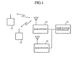
- Fig. 1 shows a construction of a mobile communications system according to a first embodiment.
- the communications system comprises a mobile station 11, a base station 12 and a base station controller 13.
- the mobile station 11 is capable of communicating with the base station 12 as it is being moved by the user carrying the mobile station 11.
- the base station 12 is equipment installed at a predefined location and is capable of simultaneous wireless communication with a plurality of mobile stations 11.
- the base station 12 is connected to a base station controller 13 hosting the base station 12 via a cable for transmission between the base station 12 and the base station controller 13.
- the base station 12 is responsible for connecting the mobile station 11 to a wire communication circuit.
- the base station controller 13 is connected to a plurality of base stations 12 and responsible for various types of control related to the base station 12.
- the base station controller 13 is also responsible for connecting the mobile station 11 to the public circuit network via the base station 12.
- a signal originating from the mobile station 11 is transmitted to a destination of communication via the base station 12, the base station controller 13 and the public circuit network (not shown).
- a signal originating from the destination of communication is transmitted to the mobile station 11 via the public circuit network, the base station controller 13 and the base station 12.
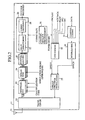
- Fig. 2 shows a construction of the mobile station of Fig. 1.
- the mobile station comprises an antenna 21, a transceiver 22, a despreading unit 23, a demapping unit 24, a deinterleaving unit 25, a channel decoding unit 26, a channel quality measuring unit 31, a converting unit 32, a channel coding unit 33, an interleaving unit 34 and a spread spectrum modulating unit 35.
- the channel decoding unit 26 is provided with a rate de-matching unit 27 and a Turbo decoding unit 28.
- a radio signal arriving from the base station is received by the antenna 21, the frequency thereof being converted by the transceiver 22 from a radio frequency to a base band frequency, which is then input to the despreading unit 23.
- the despreading unit 23 subjects the signal output from the transceiver 22 to a despreading process using a channelization code requested by the base station.
- the despread signal is output to the demapping unit 24.
- the demapping unit 24 subjects the signal output from the despreading unit 23 to conversion from an IQ symbol to bits, using a modulation scheme (QPSK/16QAM) requested by the base station.
- QPSK/16QAM a modulation scheme
- the signal output from the demapping unit 24 is subject to a deinterleaving process by the deinterleaving unit 25.
- the signal from the deinterleaving unit 25 is output to the channel decoding unit 26.
- the rate dematching unit 27 of the channel decoding unit 26 subjects the signal output from the deinterleaving unit 25 to a rate dematching process.
- the signal from the rate dematching unit 27 is subject to a Turbo decoding process by the Turbo decoding unit 28.
- the signal output from the rate dematching unit 26 is output to another processing block in the mobile station.
- the channel quality measuring unit 31 is supplied with the signal from the reception system described above so as to measure the quality of reception of the signal arriving from the base station channel by channel.
- the channel quality measuring unit 31 determines a power offset to be provided to the base station, based on the result of measurement.
- the conversion unit 32 converts TFRC, ACK/NACK, PILOT, TFCI and TPC that include a power offset value output from the channel quality measuring unit 31 into respective identification data so as to output the identification data to the spread spectrum modulating unit 35 via a dedicated physical control channel (DPCCH).
- DPCCH dedicated physical control channel
- Information data is subject to the Turbo coding process and the rate matching process in the channel coding unit 33.
- the data output from the channel coding unit 33 is subject to the interleaving process by the interleaving unit 34.
- the signal from the interleaving unit 34 is output to the spread spectrum modulating unit 35 via a dedicated physical data channel (DPDCH).
- DPDCH dedicated physical data channel
- the DPCCH data and the DPDCH data are subject to a predetermined spreading process by the spread spectrum modulating unit 35 for digital modulation according to a predetermined modulation scheme.
- the signal output from the spread spectrum modulating unit 35 is subject by the transceiver 22 to frequency conversion whereby a baseband frequency is converted into a radio frequency.
- the signal at the radio frequency is transmitted from the antenna 21.
- ACK/NACK indicates an acknowledge/negative acknowledge signal indicating to the base station whether downlink reception data is properly transmitted.
- PILOT indicates a PILOT signal providing a reference for timing/phase to be learned by the base station.
- TFCI indicates a transport format combination indicator signal indicating a combination of transport formats.
- TPC indicates a transmit power control signal provided for downlink transmission power control.
- Fig. 3 shows a construction of the base station shown in Fig. 1.
- the base station comprises a downlink packet channel (HS-DSCH) transmission process unit 41, a common pilot channel (CPICH) transmission process unit 42, a transmission process unit 43 for another channel, a multiplexing unit 44, a transceiver 45, an antenna 46, a despreading unit 63, a deinterleaving unit 64, a channel decoding unit 65, a converting unit 66, a scheduler 67 and a resource management unit 68.
- HS-DSCH downlink packet channel
- CPICH common pilot channel
- the downlink packet channel transmission process unit 41 is provided with a channel coding unit 51, an interleaving unit 52, a modulating unit 53, a multiplier unit 54 and a multiplexing unit 55.
- the channel coding unit 51 is provided with a Turbo coding unit 56 and a rate matching unit 57.
- the radio signal arriving from the mobile station is received by the antenna 46 and subject by the transceiver 45 to frequency conversion whereby a radio frequency is converted into a baseband signal.
- the signal output from the transceiver 45 is subject by the despreading unit 63 to a despreading process using a predetermined spreading code.
- the DPDCH data included in the data subjected to the despreading process is output to the deinterleaving unit 64 and the DPCCH data is output to the converting unit 66.
- the DPDCH data is subject to a deinterleaving process by the deinterleaving unit 64 and to a rate matching process and a Turbo decoding process by the channel decoding unit 65.
- the data subjected to the Turbo decoding process is transmitted to the base station controller hosting the base station.
- the DPCCH data includes identification data produced in a conversion step in the mobile station.
- the DPCCH data is converted into original TFRC, ACK/NACK, PILOT, TFCI, TPC.
- the TFRC which include a power offset value, is output by the scheduler 67 to the resource management unit 68 under predetermined timing control.
- the resource management unit 68 manages the TFRCs for each of the plurality of mobile stations.
- the TFRC stored in the resource management unit 68 is replaced by the TFRC output from the scheduler 67.
- the resource management unit 68 informs the channel coding unit 51 of a coding rate, informs the modulating unit 53 of a channelization code set and a coding scheme, and informs the multiplier 54 of a power offset value.
- the signal transmitted from the base station controller hosting the base station is subject to a Turbo coding process in the Turbo coding unit 56 and to a rate matching process in the rate matching unit 57.
- the channel coding unit 51 comprising the Turbo coding unit 56 and the rate matching unit 57 controls a combined coding rate of Turbo coding and rate matching to match the coding rate requested by the resource management unit 68.
- the signal output from the channel coding unit 51 is subject to an interleaving process by the interleaving unit 52.
- the signal subjected to the interleaving process is output to the modulating unit 53.
- the modulating unit 53 performs a digital modulation process (conversion from bits into IQ symbols), using a modulation scheme requested by the resource management unit 68.
- the modulating unit 53 performs a spreading process using the channelization code requested by the resource management unit 68.
- the signal for each channel output from the modulating unit 53 is multiplied in the multiplier 54 by a gain corresponding to the power offset value.
- the signal output from the multiplier 54 is multiplexed by the multiplexer 55.
- the signal output from the multiplexer 55 is multiplexed with the CPICH data and the signals of the other channels by the multiplexer 44.
- the signal output from the multiplexer 44 is subject by the transceiver 45 to frequency conversion whereby a baseband frequency is converted into a radio frequency for radio transmission from the antenna 46 to the mobile station.
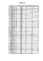
- Fig. 4 shows a table listing power offset values reported from the mobile station to the base station.
- the table of Fig. 4 lists TFRC(x,y) corresponding to information other than the power offset and indicating a TFRC type.
- the table lists identification data in association with each combination of TFRC(x,y) and power offset value.
- power offset values of 1dB and 2dB are used in addition to the default power offset value of 0dB.
- TFRC(1) in addition to 0dB, the power offset values up to 12dB in steps of 1dB are used.
- TFRC(6,y) For TFRC(6,y), a set of power offset values -1dB, -2dB, -3dB and -4dB are provided in addition to the power offset values of 0dB, 1dB and 2dB.
- TFRC(6,y) By providing TFRC(6,y) with negative power offset values, it is possible to reduce the power of transmission from the base station when the mobile station is located in the neighborhood of the base station. Accordingly, the level of interference with other channels belonging to the same cell or interference with other cells is reduced.
- Fig. 5(a) shows a BLER characteristic with respect to ⁇ Ior/Ioc
- Fig. 5(b) shows a BLER characteristic with respect to ⁇ Ior/Ioc using power offset values as parameters.
- a description of Fig. 5(a) will be given.
- ⁇ Ior and Ioc of ⁇ Ior/Ioc are defined in 3GPP TS25.101V3.8.0 as follows.
- BLER indicates a block error rate.
- the characteristic provided by different TFRCs is described in 3GPP TR25.848V4.0.0.
- TFRCs are arranged such that TFRC(1,y), TFRC(2,y), TFRC(3,y), TFRC(4,y), TFRC(5,y), TFRC(6,y), where y may take any value.
- a TFRC with a good BLER characteristic means a TFRC requiring a low level of ⁇ Ior/Ioc for a given BLER.
- the channel quality measuring unit 31 of the mobile station 11 measures the characteristic described above.
- TFRC used in downlink transmission from the base station to the mobile station is determined by level comparison between the measured characteristic and threshold values th1, th2, th3, th4 and th5.
- the threshold values are arranged such that th1, th2, th3, th4 and th5 in the ascending order of levels.
- TFRC(1,y) provides the best BLER characteristic since it requires a minimum lelvel of ⁇ Ior/Ioc. Accordingly, TFRC(1,y) is assigned to a mobile station located at a cell edge (cell boundary). TFRC(2,y)-TFRC(5,y) are assigned to the other mobile stations located successively closer to the base station. The most inward mobile station, i.e. the mobile station closest to the base station is assigned TRC(6,y).
- the power offset values are arranged such that 0dB, 1dB, 2dB, ..., 12dB in the descending order of excellence of BLER characteristic.
- the power offset value to be provided from the base station to the mobile station is determined by level comparison with threshold values th11, th21, th31, ..., th131.
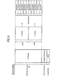
- HS-DSCH downlink packet channel
- Pt(100%) of the base station a maximum of 80% is assigned to the HS-DSCH, a maximum of 10% is assigned to the common pilot channel (CPICH), and 10% is permanently assigned to the other channels.
- CPICH common pilot channel
- the other channels include an individual physical channel for individual users, and a common control channel.
- the total HS-DSCH power Phs is assigned to two users (two mobile stations).
- a code set 71 including 5 codes is assigned to user 1 and a code set 72 including 5 codes are assigned to user 2.
- a distributed power of Phs/10 resulting from division-by-10 of the total HS-DSCH power Phs is assigned to a code of HS-DSCH.
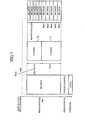
- Fig. 7 shows transmission power distribution introduced when the available power is decreased.
- Pt(100%) of the base station a maximum of 80% is assigned to the HS-DSCH, 10% is permanently assigned to the common pilot channel (CPICH), and a maximum of 10% is assigned to the other channels.
- the total HS-DSCH power Phs is assigned to two users, five codes are assigned to user 1 and five codes are assigned to user 2.
- the power assigned to code set 71 for user 1 remains Phs/2.
- the power assigned to the code set 72 for user 2 is dropped by 4dB from Phs/2 to Phs*10-0.4/2. Accordingly, the HS-DSCH power is reduced.
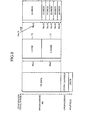
- Fig. 8 shows distribution of base station power according to a second embodiment of the present invention.
- Pt(100%) of the base station a maximum of 80% is assigned to the total HS-DSCH power, 10% is permanently assigned to the common pilot channel(CPICH) and a maximum of 10% is assigned to the other channels.
- the default power distribution is the same as that shown in Fig. 6.
- the power distribution as shown in Fig. 8 introduced.
- the total HS-DSCH power Phs is assigned to two users.
- the code set 71 comprising five codes is assigned to user 1 and the code set 72 comprising one code is assigned to user 2.
- the power assigned to the code set 71 for user 1 is Phs/2 and the power assigned to the code set 72 for user 2 is Phs/2. While the power per code for user 1 is Phs/10, the same level as shown in Fig. 6, the power per code for user 2 is Phs/2, an substantial increase from the power level of Fig. 6.
- Varying the number of codes is especially useful when the reception quality measured by the mobile station is lower than a desired reception quality. By allowing the mobile station to direct the base station to reduce the number of spreading codes used and to raise the transmission power, it is ensured that the quality of reception in the mobile station is improved.
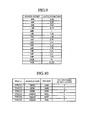
- Fig. 9 shows a table listing power offset values in association with antilogarithms.
- a requirement is that a sum of antilogarithms of power offset values for each channel does not exceed the number of codes provided in the base station (for example, 10 or 15). As long as this requirement is met, the power can be distributed as desired.
- An example for a case of 10 codes is shown in Fig. 8. In a case of 15 codes, user 1 may be assigned the number of codes of 1 and a 10dB offset, and user 2 may be assigned the number of codes of 5 and a 0dB offset.
- the mobile station is allowed to direct the base station to reduce the number of spreading codes used in addition to directing the base station to raise the transmission power, when the reception quality measured by the mobile station is lower than a desired reception quality.
- the mobile station may be allowed to direct the base station to increase the number of spreading codes used and to lower the transmission power, when the reception quality measured in the mobile station is higher than the desired reception quality.
- the total HS-DSCH power may be assigned a portion other than "a maximum of 80%".
- the invention is also useful in a configuration in which the power ratio with respect to CPICH is not constant.
Landscapes
- Engineering & Computer Science (AREA)
- Computer Networks & Wireless Communication (AREA)
- Signal Processing (AREA)
- Quality & Reliability (AREA)
- Mobile Radio Communication Systems (AREA)
Abstract
Description
For TFRC(1), in addition to 0dB, the power offset values up to 12dB in steps of 1dB are provided.
For TFRC(2,y)-TFRC(5,y), power offset values of 1dB and 2dB are used in addition to the default power offset value of 0dB. For TFRC(1), in addition to 0dB, the power offset values up to 12dB in steps of 1dB are used.
Claims (10)
- A method of controlling transmission power,
comprising the following steps:informing a transport block set size to be used from a mobile station (11) to a base station (12) based on a quality of a received signal transmitted from the base station (12);informing a power offset value corresponding to the transport block set size from the mobile station (11) to the base station (12) in order to correct a transmission power from the base station (12) to the mobile station (11), and informing a negative power offset as the power offset value when the transport block set size to be used is a maximum size; andcorrecting the transmission power from the base station (12) to the mobile station (11) based on the informed power offset value. - The method according to claim 1,
wherein the negative power offset to be informed from the mobile station (11) to the base station (12) is used only when the transport block set size to be informed is a maximum size. - The method according to claim 1 or 2,
wherein the power offset value is transmitted as identification data when the power offset value for use in the power correction of the transmission power is informed from the mobile station (11) to the base station (12). - A mobile station (11) for performing communication to a base station (12), wherein the mobile station (11) informs, to the base station (12), a transport block set size to be used based on a quality of a received signal transmitted from the base station (12), and informs, to the base station (12), a power offset value corresponding to the transport block set size in order to correct a transmission power from the base station (12) to the mobile station (11), and
wherein the mobile station (11) is capable of informing a negative power offset as the power offset value when the transport block set size to be informed is a maximum size. - A mobile communication system, having a base station (12) and a mobile station (11) which performs a radio communication to the base station (12), being capable of correcting a transmission power from the base station (12) to the mobile station (11) based on a quality of a received signal transmitted from the base station (12) and received by the mobile station (11),
wherein the mobile station (11) informs, to the base station (12), a transport block set size to be used according to the quality of the received signal transmitted from the base station (12), and informs, to the base station (12), a power offset value in order to correct the transmission power for the transport block set size, and
wherein the mobile station (11) is capable of informing a negative power offset as the power offset value when the transport block set size to be informed is a maximum size. - A method of controlling transmission power,
comprising the following steps :identifying, by a mobile station (11), a transport block set size and a modulation scheme to a base station (12), the transport block set size and the modulation scheme being based on a quality of a signal transmitted from the base station (12) and received by the mobile station (11);
identifying, by the mobile station (11), a transmission power correction value to the base station (12), wherein the transmission power correction value corresponds to the transport block set size and the modulation scheme, and the transmission power correction value is a negative value when the transport block set size is a predetermined maximum size, and when the modulation scheme is 16 QAM; andcorrecting a transmission power from the base station (12) to the mobile station (11) based on the identified transmission power correction value. - The method according to claim 6,
wherein the step of identifying a transmission power correction value comprises identifying the negative value only when the transport set size to be determined is the predetermined maximum size. - The method according to claim 6 or 7,
wherein the step of identifying a transmission power value comprises identifying the transmission power correction value as identification data. - A mobile station (11) comprising:an identification device configured to identify a transport block set size and a modulation scheme to a base station (12), the transport block set size and the modulation scheme being based on a quality of a signal transmitted from the base station (12) and received by the mobile station (11); andan identification device configured to identify a transmission power correction value to the base station (12), wherein the transmission power correction value corresponds to the transport block set size and the modulation scheme, and the transmission power correction value is a negative value when the transport block set size is a predetermined maximum size, and when the modulation scheme is 16 QAM.
- A base station (12), comprising a correction device configured to correct a transmission power from the base station (12) to a mobile station (11) based on a transmission power correction value identified by the mobile station (11),
wherein the transmission power correction value corresponds to the transport block set size and the modulation scheme,
wherein the transmission power correction value is a negative value when the transport block set size is a predetermine maximum size, and when the modulation scheme is 16 QAM, and
wherein the transport block set size and the modulation scheme is based on a quality of a signal transmitted from the base station (12) and received by the mobile station (11).
Applications Claiming Priority (3)
| Application Number | Priority Date | Filing Date | Title |
|---|---|---|---|
| JP2002029585 | 2002-02-06 | ||
| JP2002029585A JP2003234696A (en) | 2002-02-06 | 2002-02-06 | Transmission power correction method, mobile communication system and mobile station |
| EP20020024515 EP1339175A3 (en) | 2002-02-06 | 2002-10-30 | Transmission power control method, mobile communications system and mobile station |
Related Parent Applications (2)
| Application Number | Title | Priority Date | Filing Date |
|---|---|---|---|
| EP20020024515 Division EP1339175A3 (en) | 2002-02-06 | 2002-10-30 | Transmission power control method, mobile communications system and mobile station |
| EP02024515.5 Division | 2002-10-30 |
Publications (2)
| Publication Number | Publication Date |
|---|---|
| EP1592145A2 true EP1592145A2 (en) | 2005-11-02 |
| EP1592145A3 EP1592145A3 (en) | 2006-01-04 |
Family
ID=27654706
Family Applications (3)
| Application Number | Title | Priority Date | Filing Date |
|---|---|---|---|
| EP20020024515 Withdrawn EP1339175A3 (en) | 2002-02-06 | 2002-10-30 | Transmission power control method, mobile communications system and mobile station |
| EP20050014467 Withdrawn EP1592145A3 (en) | 2002-02-06 | 2002-10-30 | Transmission power control method, mobile communications system and mobile station |
| EP20050014468 Withdrawn EP1592146A3 (en) | 2002-02-06 | 2002-10-30 | Transmission power correcting method, mobile communications system and mobile station |
Family Applications Before (1)
| Application Number | Title | Priority Date | Filing Date |
|---|---|---|---|
| EP20020024515 Withdrawn EP1339175A3 (en) | 2002-02-06 | 2002-10-30 | Transmission power control method, mobile communications system and mobile station |
Family Applications After (1)
| Application Number | Title | Priority Date | Filing Date |
|---|---|---|---|
| EP20050014468 Withdrawn EP1592146A3 (en) | 2002-02-06 | 2002-10-30 | Transmission power correcting method, mobile communications system and mobile station |
Country Status (4)
| Country | Link |
|---|---|
| US (2) | US6934556B2 (en) |
| EP (3) | EP1339175A3 (en) |
| JP (1) | JP2003234696A (en) |
| CN (3) | CN1437419A (en) |
Families Citing this family (45)
| Publication number | Priority date | Publication date | Assignee | Title |
|---|---|---|---|---|
| KR100811043B1 (en) * | 2001-11-16 | 2008-03-06 | 엘지전자 주식회사 | Transmission Power Control Method for Shared Channel (SCH) and HI in Mobile Communication System |
| JP2003234696A (en) * | 2002-02-06 | 2003-08-22 | Mitsubishi Electric Corp | Transmission power correction method, mobile communication system and mobile station |
| JP3931100B2 (en) * | 2002-03-12 | 2007-06-13 | 株式会社日立コミュニケーションテクノロジー | Turbo decoder and radio base station including turbo encoder, turbo encoder and decoder |
| US8619718B2 (en) | 2002-04-05 | 2013-12-31 | Interdigital Technology Corporation | Method and apparatus for coordinating a radio network controller and node B resource management for high speed downlink packet data service |
| KR100911138B1 (en) * | 2002-04-25 | 2009-08-06 | 삼성전자주식회사 | Adaptive modulation and coding scheme for mobile power system and its method |
| US7423976B2 (en) * | 2002-09-24 | 2008-09-09 | Interdigital Technology Corporation | Block error rate estimate reporting for target signal to interference ratio adjustment |
| JP4015939B2 (en) * | 2002-12-17 | 2007-11-28 | 株式会社エヌ・ティ・ティ・ドコモ | Packet communication method, base station, mobile station, and packet communication program |
| JP4127052B2 (en) * | 2003-01-10 | 2008-07-30 | 日本電気株式会社 | Content distribution system, network, and channel switching control method |
| KR20040064864A (en) * | 2003-01-10 | 2004-07-21 | 삼성전자주식회사 | Apparatus and method for controlling reverse dtae rate in mobile communication system |
| UA80735C2 (en) * | 2003-01-31 | 2007-10-25 | Nokia Corp | Operation mode of mobile station in time division multiple access network (tdma) and a mobile station itself |
| EP1593222A1 (en) * | 2003-02-14 | 2005-11-09 | Siemens Aktiengesellschaft | Data transmission method |
| US7945280B2 (en) * | 2003-02-20 | 2011-05-17 | Fujitsu Limited | Radio channel control method and receiving apparatus |
| JP4288093B2 (en) * | 2003-04-09 | 2009-07-01 | 株式会社エヌ・ティ・ティ・ドコモ | Wireless communication control system and wireless communication control method |
| JP4367044B2 (en) * | 2003-07-23 | 2009-11-18 | 日本電気株式会社 | Communication system and transmission power control method |
| KR20050049622A (en) * | 2003-11-22 | 2005-05-27 | 엘지전자 주식회사 | Method of power control for r-cqich and r-ackch in mobile communication |
| JP4369481B2 (en) * | 2003-11-19 | 2009-11-18 | サムスン エレクトロニクス カンパニー リミテッド | Apparatus and method for transmitting / receiving common control information in a wireless communication system |
| JP4421935B2 (en) * | 2004-04-30 | 2010-02-24 | 株式会社エヌ・ティ・ティ・ドコモ | Radio base station apparatus and radio communication control method |
| CN102655672A (en) * | 2004-04-30 | 2012-09-05 | 美商内数位科技公司 | Wireless network controller |
| US8582596B2 (en) | 2004-06-04 | 2013-11-12 | Qualcomm Incorporated | Coding and modulation for broadcast and multicast services in a wireless communication system |
| US7584397B2 (en) * | 2004-06-10 | 2009-09-01 | Interdigital Technology Corporation | Method and apparatus for dynamically adjusting data transmission parameters and controlling H-ARQ processes |
| US7657277B2 (en) | 2004-09-24 | 2010-02-02 | Qualcomm Incorporated | Method and system for power control in a communication system |
| WO2007035181A2 (en) | 2004-09-24 | 2007-03-29 | Qualcomm Incorporated | Method and system for power control in a communication system having variable data rate |
| US8023554B2 (en) * | 2004-10-06 | 2011-09-20 | Broadcom Corporation | Method and system for single antenna receiver system for WCDMA |
| US7796705B2 (en) | 2004-10-15 | 2010-09-14 | Aware, Inc. | DMT symbol repetition in the presence of impulse noise |
| WO2006092976A1 (en) * | 2005-03-02 | 2006-09-08 | Nec Corporation | Downstream packet communication transmission control method and radio base station |
| BRPI0610618A2 (en) * | 2005-05-04 | 2010-07-13 | Nokia Corp | method for controlling power in the wireless communication system, computer program, network element, apparatus, method for operating the mobile station, and method for controlling power in the mobile station |
| US8042028B2 (en) | 2005-08-01 | 2011-10-18 | Nec Corporation | HS-PDSCH decoder and mobile radio-signal communication device including the same |
| JPWO2007023654A1 (en) | 2005-08-22 | 2009-02-26 | 日本電気株式会社 | Mobile communication system, mobile communication terminal, and mobile communication method |
| EP1760925A3 (en) * | 2005-09-05 | 2008-05-28 | Nokia Siemens Networks Gmbh & Co. Kg | Method and system for providing feedback information in a radio communication system |
| ATE412284T1 (en) * | 2005-11-15 | 2008-11-15 | Alcatel Lucent | METHOD FOR TRANSMITTING CHANNEL QUALITY INFORMATION IN A MULTI CARRIER RADIO COMMUNICATIONS SYSTEM AND CORRESPONDING MOBILE STATION AND BASE STATION |
| US7912471B2 (en) * | 2006-01-04 | 2011-03-22 | Wireless Technology Solutions Llc | Initial connection establishment in a wireless communication system |
| GB2435989B (en) * | 2006-03-10 | 2008-06-18 | Motorola Inc | Apparatus and method for determining a downlink transmit power characteristic in a cellular communication system |
| JP2007274134A (en) * | 2006-03-30 | 2007-10-18 | Kyocera Corp | Wireless communication apparatus and transmission power control method |
| US7903614B2 (en) * | 2006-04-27 | 2011-03-08 | Interdigital Technology Corporation | Method and apparatus for selecting link adaptation parameters for CDMA-based wireless communication systems |
| US8341397B2 (en) * | 2006-06-26 | 2012-12-25 | Mlr, Llc | Security system for handheld wireless devices using-time variable encryption keys |
| CN101110635B (en) * | 2006-07-21 | 2011-08-10 | 中兴通讯股份有限公司 | Method for area power control in orthogonal frequency division multiplexing system |
| ES2418179T3 (en) * | 2006-12-22 | 2013-08-12 | Telefonaktiebolaget Lm Ericsson (Publ) | Method and arrangement in a telecommunication system |
| GB2447439B (en) | 2007-02-02 | 2012-01-25 | Ubiquisys Ltd | Access point power control |
| GB2471681B (en) | 2009-07-07 | 2011-11-02 | Ubiquisys Ltd | Interference mitigation in a femtocell access point |
| GB2472597B (en) | 2009-08-11 | 2012-05-16 | Ubiquisys Ltd | Power setting |
| KR20110017811A (en) * | 2009-08-14 | 2011-02-22 | 삼성전자주식회사 | Control channel configuration and multiplexing method of backhaul subframe for relay |
| EP2564641B1 (en) | 2010-04-30 | 2017-06-07 | Telefonaktiebolaget LM Ericsson (publ) | Method and arrangement for load sharing power control |
| JP2013211667A (en) * | 2012-03-30 | 2013-10-10 | Kddi R & D Laboratories Inc | Mobile communication system, signal transmission system, and base station |
| US11770777B2 (en) * | 2020-09-01 | 2023-09-26 | Qualcomm Incorporated | Techniques for power control in millimeter wave systems |
| WO2024171256A1 (en) * | 2023-02-13 | 2024-08-22 | 株式会社Nttドコモ | Terminal, base station, and communication method |
Family Cites Families (16)
| Publication number | Priority date | Publication date | Assignee | Title |
|---|---|---|---|---|
| ZA965340B (en) | 1995-06-30 | 1997-01-27 | Interdigital Tech Corp | Code division multiple access (cdma) communication system |
| US5982813A (en) | 1996-09-30 | 1999-11-09 | Amsc Subsidiary Corporation | Demand-based power and data rate adjustments to a transmitter to optimize channel capacity and power usage with respect to data transmission traffic over a fixed-bandwidth channel |
| DE19651593B4 (en) * | 1996-12-11 | 2008-11-20 | Rohde & Schwarz Gmbh & Co. Kg | Arrangement for optimizing the data transmission via a bidirectional radio channel |
| US6137789A (en) | 1997-06-26 | 2000-10-24 | Nokia Mobile Phones Limited | Mobile station employing selective discontinuous transmission for high speed data services in CDMA multi-channel reverse link configuration |
| EP1758266A3 (en) | 1998-03-03 | 2014-04-23 | NEC Corporation | Method of controlling transmission power in a cellular type mobile communication system |
| US6862449B1 (en) * | 1998-05-14 | 2005-03-01 | Fujitsu Limited | Reducing interference in cellular mobile communications networks |
| JP2000278207A (en) | 1999-03-23 | 2000-10-06 | Oki Electric Ind Co Ltd | Transmission power control method and radio communication apparatus |
| DE59900771D1 (en) * | 1999-07-05 | 2002-03-14 | Alcatel Sa | Macro diversity transmission in a mobile radio system |
| KR100317267B1 (en) * | 1999-10-02 | 2001-12-22 | 서평원 | Protection method for Common Packet Channel |
| US7590095B2 (en) * | 2000-02-14 | 2009-09-15 | Qualcomm Incorporated | Method and apparatus for power control of multiple channels in a wireless communication system |
| JP3844934B2 (en) | 2000-03-03 | 2006-11-15 | 株式会社日立コミュニケーションテクノロジー | Base station apparatus, mobile communication system, and transmission power control method |
| FR2809577B1 (en) * | 2000-05-25 | 2002-10-18 | Mitsubishi Electric Inf Tech | DATA TRANSMISSION METHOD COMBATING THE DEGRADATION OF QUALITY OF SERVICE |
| US6983166B2 (en) * | 2001-08-20 | 2006-01-03 | Qualcomm, Incorporated | Power control for a channel with multiple formats in a communication system |
| JP2003234696A (en) * | 2002-02-06 | 2003-08-22 | Mitsubishi Electric Corp | Transmission power correction method, mobile communication system and mobile station |
| US7177658B2 (en) * | 2002-05-06 | 2007-02-13 | Qualcomm, Incorporated | Multi-media broadcast and multicast service (MBMS) in a wireless communications system |
| US7107014B2 (en) * | 2002-10-24 | 2006-09-12 | Nokia Corporation | Transporting power control information |
-
2002
- 2002-02-06 JP JP2002029585A patent/JP2003234696A/en active Pending
- 2002-08-13 US US10/216,771 patent/US6934556B2/en not_active Expired - Fee Related
- 2002-10-30 EP EP20020024515 patent/EP1339175A3/en not_active Withdrawn
- 2002-10-30 CN CN02148146A patent/CN1437419A/en active Pending
- 2002-10-30 CN CNB2004100566152A patent/CN100353682C/en not_active Expired - Fee Related
- 2002-10-30 EP EP20050014467 patent/EP1592145A3/en not_active Withdrawn
- 2002-10-30 CN CNA2006100999815A patent/CN1925353A/en active Pending
- 2002-10-30 EP EP20050014468 patent/EP1592146A3/en not_active Withdrawn
-
2005
- 2005-02-14 US US11/056,140 patent/US20050153726A1/en not_active Abandoned
Also Published As
| Publication number | Publication date |
|---|---|
| JP2003234696A (en) | 2003-08-22 |
| US20030148780A1 (en) | 2003-08-07 |
| EP1339175A3 (en) | 2004-01-07 |
| US20050153726A1 (en) | 2005-07-14 |
| EP1592145A3 (en) | 2006-01-04 |
| EP1592146A3 (en) | 2006-01-04 |
| EP1339175A2 (en) | 2003-08-27 |
| US6934556B2 (en) | 2005-08-23 |
| CN100353682C (en) | 2007-12-05 |
| EP1592146A2 (en) | 2005-11-02 |
| CN1925353A (en) | 2007-03-07 |
| CN1567743A (en) | 2005-01-19 |
| CN1437419A (en) | 2003-08-20 |
Similar Documents
| Publication | Publication Date | Title |
|---|---|---|
| US6934556B2 (en) | Transmission power correcting method, mobile communications system and mobile station | |
| JP4481545B2 (en) | Power control method and power control apparatus | |
| KR100459573B1 (en) | Apparatus for transmitting/receiving uplink transmission power and high speed downlink shared channel power level in communication system using high speed downlink packet access scheme and method thereof | |
| EP1341318B1 (en) | Apparatus and method for transmitting and receiving uplink power offset information in a mobile communication system supporting HSDPA | |
| US7912487B2 (en) | Mobile communication system, base station, terminal device, and transmission control method | |
| KR100493079B1 (en) | Apparatus for reporting quality of downlink channel in wide band-code division multiple access communication system using high speed data packet access scheme and method thereof | |
| CA2437736A1 (en) | Method and apparatus for transmitting messages in a wireless communication system. | |
| EP1356604A2 (en) | Method and apparatus for forward power control in a communication system | |
| EP1186117A1 (en) | Power control of network part transmitter in radio system | |
| JP2004040314A (en) | Wireless communication device and transmission allocation control method | |
| KR20030077733A (en) | Apparatus for determining report pattern of channel quality in communication system using high speed data packet access scheme and method thereof | |
| US7856210B2 (en) | Power step control for high-speed downlink shared channel packet access | |
| KR100724978B1 (en) | Apparatus and method for controlling reverse transmission power in a communication system using a high speed forward packet access method | |
| JP2005073290A (en) | Transmission power correction method, mobile communication system, and mobile station | |
| KR100842613B1 (en) | Apparatus and method for controlling high speed common control channel transmission power in time division duplexing code division multiple access communication system using high speed forward packet access method | |
| KR20040016330A (en) | Apparatus for controlling transmission power of high speed shared information channel in time division duplexing code division multiple access communication system using high speed downlink packet access scheme and method thereof | |
| KR20090011117A (en) | Method for tracking block error rate at base station of mobile communication system using high speed forward packet access method | |
| AU2002322425A1 (en) | Method and apparatus for transmitting messages in a wireless communication system | |
| AU2002243379A1 (en) | Method and apparatus for forward power control in a communication system |
Legal Events
| Date | Code | Title | Description |
|---|---|---|---|
| PUAI | Public reference made under article 153(3) epc to a published international application that has entered the european phase |
Free format text: ORIGINAL CODE: 0009012 |
|
| AC | Divisional application: reference to earlier application |
Ref document number: 1339175 Country of ref document: EP Kind code of ref document: P |
|
| AK | Designated contracting states |
Kind code of ref document: A2 Designated state(s): DE FR GB |
|
| PUAL | Search report despatched |
Free format text: ORIGINAL CODE: 0009013 |
|
| AK | Designated contracting states |
Kind code of ref document: A3 Designated state(s): DE FR GB |
|
| RIC1 | Information provided on ipc code assigned before grant |
Ipc: H04L 1/00 20060101ALI20051115BHEP Ipc: H04B 7/005 20060101AFI20050909BHEP |
|
| RAP1 | Party data changed (applicant data changed or rights of an application transferred) |
Owner name: MITSUBISHI DENKI KABUSHIKI KAISHA |
|
| AKX | Designation fees paid |
Designated state(s): DE FR GB |
|
| 17P | Request for examination filed |
Effective date: 20060907 |
|
| 17Q | First examination report despatched |
Effective date: 20061005 |
|
| STAA | Information on the status of an ep patent application or granted ep patent |
Free format text: STATUS: THE APPLICATION HAS BEEN WITHDRAWN |
|
| 18W | Application withdrawn |
Effective date: 20100701 |