Background of the Invention
1. Field of the Invention
-
The present invention relates to a technique for
recording a user data on an optical disc medium, and more
particularly to an optical disc medium, an optical disc
apparatus using the same, and a recording method on the
same.
2. Description of the Related Art
-
In an optical disc field in which data are recorded
and played by using a small optical beam, a ROM (Read Only
Memory) medium for playback-only has been first widely
spread, in which an embossed data pit string is formed.
Then, a CD-R (Compact Disc-Recordable) and a DVD-R (Digital
Versatile Disc-Recordable) are now widely spread, in which
user data can be recorded. Also, optical disc media called
CD-RW (CD-ReWritable) and DVD-RW (DVD-ReWritable) are
known, to which data can be rewritten. Here, the optical
disc media that the user data can be recorded are
generically referred to as a recording type optical disc
medium.
-
In the recording type optical disc medium, a
spiral groove track is formed on an optical disc substrate,
and a multi-layered recording layer made of an organic
material and the like is formed thereon. A laser beam of
high power is focused on this recording layer for changing
the property of the recording layer to form a record pit.
Thus, a data is recorded on the optical disc medium as the
record pits. The optical disc medium after the recording
operation has a same data format as the ROM medium, and
a servo signal of the substantially same property as the
ROM medium can be obtained form the optical disc medium
on which the data recorded. Thus, the playback-only
optical disc apparatus can carry out the playback of the
recorded user data on the optical disc medium.
-
Also, in the DVD-R, a format of the user data are
converted into a format in which a data ID such as an
address, and an error correction code are added to the user
data. Then, the user data are recorded as a series of
continuous data on the optical disc medium. This
continuous record format is the same format as that of the
DVD-ROM.
-
However, if the optical disc medium is given the
perfectly same format as the DVD-ROM, the user data can
be recorded only once. Therefore, recording methods
called a multi-session and a multi-border are adopted to
permit the user data to be recorded additionally several
times. In this case, a special data called a border area
where data of a data position and the like are recorded
is provided after the user data, and another user data are
further recorded thereafter. A playing apparatus can play
the user data by using the data position data.
-
In conjunction with the above description, the
following techniques for writing data into a rewritable
recording medium such as CD-RW or DVD-RAM are disclosed.
-
Japanese Laid Open Patent Application (JP-A
2000-504462) discloses a writing apparatus which includes
a writing unit and a positioning unit. The writing unit
writes a mark indicating a data block in an area of a
recording medium with an electromagnetic emission beam,
in order to write the data block on a track pattern of the
rewritable recording medium. The positioning unit
positions the writing unit in accordance with a track
structure of the recording medium. The track structure
has the track pattern. Such a writing apparatus has a first
detecting unit, a second detecting unit and an initializing
unit. The first detecting unit detects the area of the
recording medium used to write the data block. The second
detecting unit detects a non-written boundary area
adjacent to the used area. The initializing unit writes
a dummy data to the non-written boundary area.
-
Also, Japanese Laid Open Patent Application (JP-A
2000-504463) discloses a writing apparatus, which writes
a data block to a track pattern on a writable recording
medium. This writing apparatus includes a writing unit
and a positioning unit. The writing unit writes a mark
indicating a data block into the region of the recording
medium with an electromagnetic emission beam. The
positioning unit positions the writing unit on the
recording medium in accordance with a track structure
indicating a track pattern. This writing apparatus
includes a state unit for generating a state data to
indicate the fact that a write operation is carried out
on at least one region of the recording medium. In the
writing apparatus, the state data is extended from a start
section of the track pattern region in which the data block
is written, and has an initial region data for indicating
an initial region to which it is written without any
interruption.
Summary of the Invention
-
An object of the present invention is to provide an
optical disc medium, and an optical disc apparatus using
the same, and a recording method on the same, in which a
time for recording data can be reduced.
-
Another object of the present invention is to provide
an optical disc medium, and an optical disc apparatus using
the same, and a recording method on the same, in which
larger amount of data can be recorded than before.
-
This and other objects, features and advantages of
the present invention will be readily ascertained by
referring to the following description and drawings.
-
In order to achieve an aspect of the present invention,
the present invention provides an optical disc medium
including: a system area in which system data are recorded,
and a data area in which user data are recorded. The data
area includes: a plurality of bordered areas in which the
user data are recorded, and a plurality of border areas
each of which separates adjacent two of the plurality of
bordered areas. A most outer border area is a finalization
area, the most outer border area is one of the plurality
of border areas and placed at the most outer side, and the
finalization area is a final area in which data are
recorded.
-
In the optical disc medium, a finalization
identifying data may be recorded in at least one of the
plurality of border area. The finalization identifying
data identifies that the most outer border area is the
finalization area.
-
In the optical disc medium, each of the plurality of
border area except for the finalization area may include
a border-in area. The border-in area adjoins one of the
plurality of bordered areas at an outer side and includes
an area in which an area combination flag is recorded. The
area combination flag indicates that whether or not an
outer side adjacent one of the plurality of border area
to an outer side adjacent one of the bordered area is the
finalization area.
-
In the optical disc medium, an attribute data may be
recorded in each of the plurality of the border area. The
attribute data indicates a kind of recorded data. A first
attribute data of the finalization area is different from
a second attribute data of the plurality of border area
except for the finalization area.
-
In the optical disc medium, the first attribute data
may be a lead-out attribute data.
-
In the optical disc medium, each of the plurality of
border area may include a border-out area. The border-out
area adjoins one of the plurality of bordered areas at an
inner side and includes an area in which a dummy data is
recorded. A first dummy data of the finalization area is
different from a second dummy data of the plurality of
border area except for the finalization area.
-
In the optical disc medium, the first dummy data may
be FF in hexadecimal notation.
-
In order to achieve another aspect of the present
invention, the present invention provides an optical disc
apparatus including: a rotation driving system configured
to rotate an optical disc medium, an access section; and
a control section configured to control the rotation
driving system to rotate the optical disc medium. The
control section is also configured to encode record data
and to control the access section to irradiate a laser beam
such that the encoded record data is recorded on the optical
disc medium as the user data. The optical disc medium
includes a system area, in which system data are recorded
and a data area in which user data are recorded. The
control section controls the access section such that the
user data are recorded in a plurality of bordered areas
in the data area, and such that each of a plurality of border
areas separates adjacent two of the plurality of bordered
areas. Also, the control section controls the access
section such that a most outer border area is a finalization
area. The most outer border area is one of the plurality
of border areas and placed at the most outer side. The
finalization area is an final area in which data are
recorded. Also, the control section controls the access
section such that a finalization identifying data is
recorded in at least one of the plurality of border area.
The finalization identifying data identifies that the most
outer border area is the finalization area.
-
In the optical disc apparatus, the control section
may control the access section such that each of the
plurality of border area except for the finalization area
includes a border-in area, and such that the border-in area
adjoins one of the plurality of bordered area at an outer
side and includes an area in which an area combination flag
is recorded, the area combination flag indicates that
whether or not an outer side adjacent one of the plurality
of border area to an outer side adjacent one of the bordered
area is the finalization area.
-
In the optical disc apparatus, the control section
may control the access section such that an attribute data
is recorded in each of the plurality of the border area,
the attribute data indicates a kind of recorded data, and
such that a first attribute data of the finalization area
is different from a second attribute data of the plurality
of border area except for the finalization area.
-
In the optical disc apparatus, the control section
may control the access section such that the first
attribute data is a lead-out attribute data.
-
In the optical disc apparatus, the control section
may control the access section such that each of the
plurality of border area includes a border-out area, such
that the border-out area adjoins one of the plurality of
bordered area at an inner side and includes an area in which
an dummy data is recorded, and such that a first dummy data
of the finalization area is different from a second dummy
data of the plurality of border area except for the
finalization area.
-
In order to achieve still another aspect of the
present invention, the present invention provides an
optical disc apparatus including: a rotation driving
system, an access section and a control section. The
rotation driving system is configured to rotate an optical
disc medium. The optical disc medium includes: a system
area in which system data are recorded, and a data area
in which user data are recorded. The data area includes:
a plurality of bordered areas in which the user data are
recorded, and a plurality of border areas each of which
separates adjacent two of the plurality of bordered areas.
A most outer border area is a finalization area. The most
outer border area is one of the plurality of border area
and placed at the most outer side. The finalization area
is an final area in which data are recorded. A
finalization identifying data is recorded in at least one
of the plurality of border area. The finalization
identifying data identifies that the most outer border area
is the finalization area. The control section is
configured to control the rotation driving system to rotate
the optical disc medium, and to control the access section
to irradiate a laser beam such that the finalization
identifying data in the at least one of the plurality of
border area is read that the most outer border area is
recognized as the finalization area.
-
In the optical disc apparatus, each of the plurality
of border area except for the finalization area may include
a border-in area. The border-in area adjoins one of the
plurality of bordered area at an outer side and includes
an area in which an area combination flag is recorded. The
area combination flag indicates that whether or not an
outer side adjacent one of the plurality of border area
to an outer side adjacent one of the bordered area is the
finalization area. The control section controls the
access section such that the area combination flag is read
that the outer side adjacent one of the plurality of border
area is recognized as the finalization area.
-
In the optical disc apparatus, an attribute data may
be recorded in each of the plurality of the border area.
The attribute data indicates a kind of recorded data. A
first attribute data of the finalization area is different
from a second attribute data of the plurality of border
area except for the finalization area. The control
section controls the access section such that the first
attribute data is read that one of the plurality of the
border area is recognized as the finalization area.
-
In the optical disc apparatus, the first attribute
data may be a lead-out attribute data.
-
In the optical disc apparatus, each of the plurality
of border area may include a border-out area. The
border-out area adjoins one of the plurality of bordered
area at an inner side and includes an area in which an dummy
data is recorded. A first dummy data of the finalization
area is different from a second dummy data of the plurality
of border area except for the finalization area. The
control section controls the access section such that the
first dummy data is read that one of the plurality of the
border area is recognized as the finalization area.
In order to achieve still another aspect of the present
invention, the present invention provides a data recording
method in an optical disc medium which includes a system
area and a data area, the data recording method including:
(a) setting a border area and a bordered area in the data
area; (b) recording user data in the bordered area; (c)
repeating the steps (a) to (b) until recording of the user
data is finished; and (d) recording a finalization
identifying data in a most outer border area. The
finalization identifying data identifies that the most
outer border area is a finalization area, the finalization
area is an final area in which data are recorded. The most
outer border area is placed at the most outer side of the
optical disc medium.
-
In the data recording method, the step (a) may include
(a1) setting a border-in area in the border area. The
border-in area adjoins the bordered area at an outer side
and includes an area in which an area combination flag is
recorded. The area combination flag indicates that
whether or not the outer side adjacent border area to the
outer side adjacent the bordered area is the finalization
area. The step (d) may include (d1) recording the area
combination flag in the border-in area in a most outer
border area.
-
In the data recording method, the step (b) may
include: (b1) setting a border-out area in the border area,
and (b2) recording a second attribute data in the
border-out area. The step (d) may include (d2) recording
a first attribute data in the border-out area in a most
outer border area. The first and second attribute data
indicate kinds of recorded data.
-
In the data recording method, the first attribute
data may be a lead-out attribute data.
-
In the data recording method, the step (b) may include
(b3) setting a border-out area in the border area, and (b4)
recording a second dummy data in the border-out area. The
step (d) may include: (d3) recording a first dummy data
in the border-out area in a most outer border area.
Brief Description of the Drawings
-
- Fig. 1 is a block diagram showing the configuration
of the data recording system of the present invention;
- Fig. 2 is a block diagram showing the configuration
of the optical disc apparatus 4 according to the present
invention;
- Fig. 3 is a diagram showing the format of the
recording type optical disc medium 6;
- Fig. 4 is a schematic diagram showing the area
arrangement on the optical disc medium 6 along the radius
direction;
- Fig. 5 is a schematic diagram showing an arrangement
of various areas in the optical disc medium 6 of the first
embodiment;
- Fig. 6 is a flowchart showing a recording operation
of the first embodiment;
- Fig. 7 is a flowchart showing a playing operation of
the first embodiment;
- Fig. 8 is a schematic diagram showing an arrangement
of various areas in the optical disc medium 6 of the second
embodiment;
- Fig. 9 is a flowchart showing a recording operation
of the second embodiment;
- Fig. 10 is a flowchart showing a playing operation
of the second embodiment;
- Fig. 11 is a schematic diagram showing an arrangement
of various areas in the optical disc medium 6 of the third
embodiment;
- Fig. 12 is a flowchart showing a recording operation
of the third embodiment; and
- Fig. 13 is a flowchart showing a playing operation
of the third embodiment.
-
Description of the Preferred Embodiments
-
Hereinafter, a data recording system for an
optical disc apparatus using an optical disc medium of the
present invention will be described in detail with
reference to the attached drawings.
-
Fig. 1 is a block diagram showing the
configuration of the data recording system of the present
invention. The data recording system is provided with a
host apparatus 2 and an optical disc apparatus 4. The
optical disc apparatus 4 is set with an optical disc medium
6 such as a DVD (Digital Versatile Disc), and records data
on the optical disc medium 6 or plays the data from the
optical disc medium 6, in response to a command from the
host apparatus 2. Also, the optical disc apparatus 4
carries out a training process for checking and adjusting
a record condition in response to a command from the host
apparatus 2 prior to starting the writing operation.
-
Fig. 2 is a block diagram showing the
configuration of the optical disc apparatus 4 according
to the present invention. The optical disc apparatus 4
of the first embodiment is provided with a CPU 10, an access
section 12, a disc controller 14, an encoder 16, a decoder
18 and a rotation driving system 20. A control section
(not shown in Fig. 2) includes the CPU 10, the disc
controller 14, the encoder 16 and the decoder 18.
-
The CPU 10 controls the entire operation of the
optical disc apparatus 4. The CPU 10 exchanges commands,
instructions, notices and data with the host apparatus 2,
and controls the disc controller 14, the encoder 16 and
the decoder 18, and also carries out a necessary
calculation. The access section 12 contains a laser
diode, uses a laser beam to write a data onto the optical
disc medium 6 and plays (reads) the data from the optical
disc medium 6. The access section 12 is well known to a
skilled person in the art. The rotation driving system
20 drives the optical disc medium 6 in response to a command
from the CPU 10 so that the optical disc medium 6 is rotated,
when the optical disc medium 6 is set.
-
The disc controller 14 controls the access section
12 and the rotation driving system 20 such that the optical
disc medium 6 is rotated, a laser control is carried out
and the recording and playing (reading) operations to the
data on the optical disc medium 6 are carried out. The
disc controller 14 drives the rotation driving system 20
to rotate the optical disc medium 6 in accordance with a
command from the CPU 10. Also, the disc controller 14
controls the position of the access section 12 in
accordance with a command from the CPU 10, and also controls
the operation of the access section 12 in the recording
and playing operations. In the recording operation, the
disc controller 14 controls the access section 12 to read
data necessary to carry out the recording operation from
the optical disc medium 6, and to record the data sent from
the encoder 16 onto the optical disc medium 6 based on the
read-out necessary data. At this time, the access section
12 outputs the laser beam to record the data onto the
optical disc medium 6. Also, in the playing operation,
the disc controller 14 controls the access section 12 to
play the data from the optical disc medium 6. The access
section 12 outputs the laser beam to play the data from
the optical disc medium 6. The outputted data is sent
through the disc controller 14 to the decoder 18.
-
The encoder 16 carries out an encoding process on
user data in response to a command from the CPU 10. For
example, in case of the DVD, the encoder 16 generates a
record data in units of ECC (error correction code) blocks,
each of which includes 16 sectors. The generated record
data is sent to the access section 12 through the disc
controller 14.
-
The decoder 18 carries out a decoding process of
the data from the optical disc medium 6 in units of the
ECC blocks in response to a command from the CPU 10. A
configuration in which the ECC block is extended to 32
sectors is proposed in a next generation DVD.
-
In a recording type optical disc medium 6 such as
a DVD-R and a DVD-RW, a spiral groove track for tracking
is formed on an optical disc substrate. A multi-layered
recording layer made of an organic material and the like
is formed thereon. The laser beam with high power is
focused on this recording layer to partially change the
recording layer and to form record pits. Thus, the data
is recorded on the optical disc medium 6. The optical disc
medium 6 after the recording operation has the same data
format as that of the embossed optical disc ROM medium
(DVD-ROM or the like) . Also, since a servo signal having
the substantially same characteristics as the optical disc
ROM medium can be obtained, the recorded data from the
optical disc medium 6 can be played by an playback-only
apparatus.
-
Fig. 3 is a diagram showing the format of the
recording type optical disc medium 6. Referring to Fig.
3, the recording type optical disc medium 6 has a system
area 22, a data area 23 and a lead-out area (not shown)
in a concentric manner from the inner circumference side.
-
The system area 22 is used to record system data
necessary for the recording and playing operations,
including disc data and data indicative of a user data area
in which user data are recorded. An area in which record
control data are recorded to control the optical disc
medium 6 and an area used to check record conditions are
secured in the system area 22.
-
The lead-out area indicates the end of the storage
area on the optical disc medium 6. When the lead-out area
is detected, it is recognized that the recording operation
of the data is ended on the optical disc medium 6, and cannot
be carried out.
-
The data area 23 is located between the system area
22 and the lead-out area and is used to record the user
data. A spiral recording track 24 is formed in the data
area 23.
-
Fig. 4 is a schematic diagram showing the area
arrangement on the optical disc medium 6 along the radius
direction. The area arrangement will be described below.
In Fig. 4, the left side indicates the inner circumference
side of the optical disc medium 6, and the right side
indicates the outer circumference side thereof. The
system area 22 on the inner circumference side includes
system control data necessary when the optical disc
apparatus 4 carries out the recording and playing
operations, and arrangement data of recorded data on the
optical disc medium 6. The system area 22 is roughly
classified into three areas of a test record area 26, a
record control data area 27 and a user data lead-in area
28.
-
The user data lead-in area 28 is arranged on the
side closest to the data area 23. This area is used to
record system control data necessary when already recorded
data are played from the recording type optical disc medium
6 by the playback-only optical disc apparatus. That is,
an arrangement of the user data is recorded in the user
data lead-in area 28.
-
The record control data area 27 is used to record
control data about portions of the data area 23, i.e., data
necessary for the optical disc apparatus 4 to record user
data in the data area 23. The record control data contains
data associating with a next recordable position in the
data area 23, and the usage situation of the test record
area 26. In accompaniment with the increase in the user
data recorded in the data area 23, the data of the record
control data area 27 is sequentially updated and increased.
Thus, a new record control data is additionally recorded
in a predetermined unit from the inner circumference side
to the outer circumference side.
-
The test record area 26 is used for a trial
recording operation to check the condition optimal to the
recording operation. In order to optimize the recording
condition in the data area 23, the trial recording is
carried out while a power, a record waveform and the like
are changed. Although the inside of the test record area
26 may be used in any order, typically, the outer
circumference side is firstly used in many cases.
-
In such an optical disc medium 6, a border area
is provided prior to the finalization such that the
playback-only apparatus can play the recorded user data,
namely, compatibility with the playback-only apparatus can
be attained. An area segmented by the border areas is
referred to as a bordered area.
(First Embodiment)
-
Hereinafter, a first embodiment of the present
invention will be explained with reference to Figs. 5 to
7. In the first embodiment, a border-in area in a border
area includes a flag that shows a borer area recorded in
the most outer side is a finalization area.
-
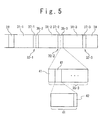
Fig. 5 is a schematic diagram showing an arrangement
of various areas in the optical disc medium 6 of the first
embodiment. Referring to Fig. 5, the arrangement of
various areas will be described below. The optical disk
medium 6 in the first embodiment includes the data area
23 in the outer side of the user data lead-in area 28 in
the system area 22.
-
As shown in Fig. 5, the data area 23 includes a
plurality of bordered areas 31-1 to 31-3 and border areas
32-1 to 32-3. The data area 23 with three bordered areas
and three border areas is explained here, however the
present invention cannot be limited to that. The border
area 32-1 includes a border-out area 37-1 and a border-in
area 35-2. The border area 32-2 includes a border-out area
37-2 and a border-in area 35-3. The border area 32-3
includes a border-out area 37-3. In each border-out area,
a border-out data is recorded.
-
That is, the bordered area 31-1, which is on the most
inner side, is sandwiched by the user data lead-in area
28 and the border-out area 37-1. The bordered area 31-2
is sandwiched by the border-in area 35-2 and the border-out
area 37-2. The bordered area 31-3 is sandwiched by the
border-in area 35-3 and the border-out area 37-3.
-
Border-in data including format data is recorded in
the border-in areas 35-2 and 35-3 as well as the user data
lead-in area 28. The format data includes a kind of the
medium, a version number of the specifications, a position
of the following border area and the like. For instance
in the DVD-R, the format data with one ECC block length
is repeatedly recorded in several times in the border-in
data, and the border-in data is recorded in the border-in
areas 35-2 and 35-3. Therefore, several numbers of the
ECC blocks 41, in which the format data are recorded, are
provided in the border-in areas 35-2 and 35-3.
-
In the first embodiment, the bordered area 31-3 is
the most outer area to which the user data are recorded.
The outer side of the border area 32-3 is an unrecorded
area 39. An area combination flag 42, which shows whether
or not the border area 32-3 is finalized, is added and
recorded in addition to the format data.
-
That is, since the area combination flag 42 set in
the format data area 41 in the border-in area 35-3 indicates
ON, it is shown that the bordered area 31-3 following the
border-in area 35-3 is the most outer side area where the
user data are to be recorded, and the outer side of the
border area 32-3 becomes the unrecorded area 39. Moreover,
since the area combination flag 42 indicates OFF in the
format data area 41 in the border-in area 35-2, it is shown
that the bordered area 31-3 where the user data are to be
recorded exists in the outer side of the bordered area 31-2
following the border-in area 35-2.
-
In this way, as the area combination flag 42 is
recorded in the border-in areas 35-2 and 35-3 as a part
of the format data, it is possible to omit the user data
lead-out area, which has been provided on the most outer
side of the optical disk medium 6 so far. As a result,
a processing time for recording a user data lead-out data
can be reduced, and a recording time can be shortened.
Here, an exclusive flag bit may be allocated for the area
combination flag. The same function may be achieved by
assigning a particular data, such as "00", to specify the
following border-in area address.
-
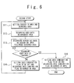
Next, an operation of the first embodiment will be
described with reference to attached drawings. Fig. 6 is
a flowchart showing a recording operation of the first
embodiment. In this recording operation, the optical disc
apparatus 4 records the user data to the optical disk medium
6. The optical disc apparatus 4 (CPU 10) sets an area for
recording data in the optical disc medium 6 in response
to the instruction to record the user data in the optical
disk medium 6. In the case that the instruction for
recording the additional user data have been received after
the user data have been recorded in the range of the
bordered area 31-1, the user data are already recorded in
the rage of the border-out area 37-1. Therefore, as the
start address of the border-in area that records the format
data is determined, the optical disc apparatus 4 (CPU 10)
sets the end address to clarify the range of the border-in
area 35-2. After the range of the border-in area 35-2 is
determined, the start address of the bordered area 31-2
adjacent to the border-in area 35-2 is determined. Then,
it is possible to record the user data (step S11).
-
Setting the area for recording the user data, the
optical disc apparatus 4 (CPU 10) records the user data
in the bordered area 31-2 (step S12). For example of the
data recording step, the CPU 10 controls the encoder 16
to encode the data if the data are the user data, and
controls disc controller 14, which controls the rotation
driving system 20 and the access section 12, to records
the data in the predetermined area. Same step may be used
for recording of any data in the optical disc medium 6.
-
After the user data are recorded, the optical disc
apparatus 4 (CPU 10) records the border-out data following
the bordered area 31-2 in which the user data is recorded.
The area, in which the border-out data is recorded, becomes
the border-out area 37-2 (step S13).
-
The optical disc apparatus 4 (CPU 10) receives an
instruction from the host apparatus 2 whether or not
further additional user data exist, and whether or not the
optical disk medium 6 should record any other user data
after recording all the user data (step S14).
-
In case that the additional user data exit (step S14:
NO), the optical disc apparatus (CPU 10) 4 sets the area
combination flag 42 to be OFF, and then records the area
combination flag 42 in the border-in area 35-2 together
with the other format data (step S16).
-
On the other hand in case that the additional data
to be recorded in the optical disk medium 6 does not exit
after recording all the user data, such as the case that
the user data is in the bordered area 31-3 in Fig. 5 (step
S14: YES), the optical disc apparatus 4 (CPU 10) sets the
area combination flag 42 to be ON, and then records the
area combination flag 42 in the border-in area 35-3
together with the other format data. Moreover, the
optical disc apparatus 4 (CPU 10) executes the processing
needed for finalization, such as recording dummy data in
the unrecorded part of the system area 22 (step S18) . The
recording into the optical disk medium 6 is completed
remaining the unrecorded area 39 without recording the data
in the outer side of the border-out area 37-3.
-
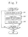
Fig. 7 is a flowchart showing a playing operation of
the first embodiment. In this playing operation, the
optical disc apparatus 4 plays the user data on the optical
disk medium 6. The user data were recorded in the optical
disk medium 6 as mentioned above. In the playing of the
user data recorded in the optical disk medium 6, the optical
disc apparatus 4 (CPU 10) firstly accesses the user data
lead-in area and the border-in area in order to read the
format data recorded in the user data lead-in data or the
border-in data (step S21) . For example of the data reading
step, the CPU 10 controls the disc controller 14, which
controls the rotation driving system 20 and the access
section 12, to reads the data in the predetermined area.
-
The area combination flag 42 in the loaded format data
indicate whether or not the bordered area 31 following the
accessed border-in area 35 is the last area in which the
user data is recorded. Therefore, the optical disc
apparatus 4 (CPU 10) stores the data of the area combination
flag 42 in the memory (not shown) (step S23).
-
The optical disc apparatus 4 (CPU 10) accesses the
bordered area 31, reads and plays the user data (step S25) .
For example of the user data playing step, the CPU 10
controls disc controller 14, which controls the rotation
driving system 20 and the access section 12, to reads the
user data in the predetermined area, and controls the
decoder 18 to decode and plays the user data.
-
Finishing the playing of the user data from the
bordered area 31, the optical disc apparatus 4 (CPU 10)
confirms the data of the area combination flag 42 stored
in the step S23 (step S27). In the case of the playing
of the user data of the bordered area 31-2, since the area
combination flag 42 indicates OFF (the step S27 : OFF), the
bordered area 31-3 in which the user data are recorded exist.
Therefore, the operation returns to the step S21 and the
optical disc apparatus 4 (CPU 10) plays the user data in
the following bordered area 31-3.
-
In the case of the playing of the user data of the
bordered area 31-3, since the area combination flag 42
indicates ON (the step S27: ON), the border area 32-3
following the bordered area 31-3 from which the user data
are played, is the last area recorded in the optical disk
medium 6. Therefore, the playing the user data is
finished.
-
Thus, because the border-in area 35 includes a flag
(the area combination flag 42 in the border-in area 35-3),
the border-out data in the border area 32-3 (the border-out
area 37-3) in the most outer side can be used for the
function of the user data lead-out data. Therefore, it
is not necessary to allocate the user data lead-out area
independently and the record area can be effectively used.
Moreover, it is possible to reduce the amount of the
recorded data in the optical disk medium 6 and the recording
time can be shortened.
(Second Embodiment)
-
Hereinafter, a second embodiment of the present
invention will be explained with reference to Figs. 8 to
10. In the second embodiment, a border-out area in a
border area includes a flag that indicates that a border
area recorded in the most outer side is a finalization area.
-
Fig. 8 is a schematic diagram showing an arrangement
of various areas in the optical disc medium 6 of the second
embodiment. Referring to Fig. 8, the arrangement of
various areas will be described below. The optical disk
medium 6 in the second embodiment includes the data area
23 in an outer side of the user data lead-in area 28 in
the system area 22. As shown in Fig. 8, the data area 23
includes a plurality of bordered areas 31-1 to 31-3 and
border areas 32-1 to 32-3. The data area 23 with three
bordered areas and three border areas is explained here,
however the present invention cannot be limited to that.
The border area 32-1 includes a border-out area 37-1 and
a border-in area 35-2. The border area 32-2 includes a
border-out area 37-2 and a border-in area 35-3. The border
area 32-3 includes a border-out area 37-3. In each
border-out area, a border-out data is recorded.
-
That is, the bordered area 31-1, which is on the most
inner side, is sandwiched by the user data lead-in area
28 and the border-out area 37-1. The bordered area 31-2
is sandwiched by the border-in area 35-2 and a border-out
area 37-2. The bordered area 31-3 is sandwiched by
the border-in area 35-3 and the border-out area 37-3.
-
In these record areas, data are recorded in every
sector, which is basic unit of 2 kilobytes for a record
area. Therefore, the border-out data are recorded in some
sectors 51 in each of the border-out areas 37-1 to 37-3.
The sector 51 includes a data area 58 and a head area
53. The data area 58 records data. The header area 53
records a sector address indicating a sequence of recording
and playing, additional data and the like. The header area
53 includes an area 55 which records an area type data
including an attribute flag. An area type shown in the
area type data indicates which area of a record attribute
(category) the sector 51 belongs to.
-
The area type has three kinds of attributes of a
lead-in, a data, and a lead-out. The lead-in attribute
indicates that the sector belongs to the user data lead-in
area 28 and the sector is in the system area. The lead-out
attribute indicates that the sector belongs to the user
data-out area and the sector is in the system area. The
data attribute indicates that the sector belongs to the
area where the user data are recorded. That is, the data
attribute shows that the sector belongs to the area other
than the system area. The border-in area 35 and the
border-out area 37 are areas where the user data is recorded
usually, and the border-in area 35 and the border-out area
37 have the data attribute.
-
The lead-out attribute is given to the border-out
area 37-3 in the second embodiment. That is, when the
optical disc apparatus 4 records the border-out data, the
lead-out attribute is given to the sector 51 in the
border-out area 37-3 in the case that the recording in the
optical disk medium 6 is completed at the border-out area.
The lead-out attribute data recorded in the border-out area
37-3 indicates that the border-out area 37-3 is the most
outer side of the data recorded areas in the optical disk
medium 6, and only unrecorded area 39 exists outside the
border-out area 37-3. Having the lead-out attribute data
by the border-out area 37-3, it is possible to omit the
user data lead-out area, which is conventionally provided
in the most outer side of the optical disk medium 6 so far.
Therefore, the processing time to record the user data
lead-out data can be reduced, and recording time can be
shortened. In this example, the border-out area, to which
the lead-out attribute is given, has a function of the
lead-out area as a simultaneous use. However, another
attribute that indicates the simultaneous use may be
applied.
-
Next, an operation of the second embodiment will be
described with reference to attached drawings. Fig. 9 is
a flowchart showing a recording operation of the second
embodiment. In this recording operation, the optical disc
apparatus 4 records the user data to the optical disk medium
6. The optical disc apparatus 4 (CPU 10) sets an area for
recording data in the optical disk medium 6 in response
to the instruction to record the user data in the optical
disk medium 6. In the case that the instruction for
recording additional user data have been received after
the user data has been recorded in the range of the bordered
area 31-1, the user data are already recorded in the range
of the border-out area 37-1. Therefore, as the start
address of the border-in area that the format data is
determined, the optical disc apparatus 4 (CPU 10) sets an
end address to clarify the range of the border-in area 35-2.
After the range of the border-in area 35-2 is determined,
the start address of the bordered area 31-2 adjacent to
the border-in area 35-2 is determined. Then, it is
possible to record the user data (step S31).
-
Setting the area to record the user data, the optical
disc apparatus 4 (CPU 10) records the user data in the
bordered area 31-2 (step S32). For example of the data
recording step, the CPU 10 controls the encoder 16 to encode
the data if the data are the user data, and controls disc
controller 14, which controls the rotation driving system
20 and the access section 12, to records the data in the
predetermined area. Same step may be used for recording
of any data in the optical disc medium 6.
-
After the user data are recorded, the optical disc
apparatus 4 (CPU 10) receives an instruction from the host
apparatus 2 whether or not additional user data exist to
be recorded in the optical disk medium 6 after the recording
of all the user data (step S33).
-
In the case that the additional user data exist (step
S33: NO), the optical disc apparatus 4 (CPU 10) records
the border-out data in the border area 32-2 following the
bordered area 31-2 with the recorded user data. At this
time, the attribute (attribute flag) given to the
border-out area 37-2 is the data attribute. Therefore,
the area type 55 that is recorded in the sector 51 is set
as the data attribute. Then, the optical disc apparatus
4 (CPU 10) records the border-out data in the border-out
area 37-2 (step S35).
-
Since the border-out data is recorded in the
border-out area 37-2, the recording position of the border
area 32-2 is defined. Therefore, the position of the
following border area for recording the format data is
determined. Thus, the format data to be recorded in the
border-in area 35-2 is determined, and the optical disc
apparatus 4 (CPU 10) records the format data in the
border-in area 35-2 (step S36). The optical disc
apparatus 4 (CPU 10) receives an instruction from the host
apparatus 2 to record the following user data, and then
the operation is repeated from the step S31.
-
In the step S32, when the last user data of the optical
disk medium 6 is recorded in the bordered area 31-3, the
optical disc apparatus 4 (CPU 10) receives an instruction
from the host apparatus 2 whether or not additional user
data exist to be recorded in the optical disk medium 6 after
the recording of all the user data (step S33) . In the case
that the additional user data to record in the optical disk
medium 6 does not exist after all the user data is recorded
(step S33: YES), the optical disc apparatus 4 (CPU 10)
records the border-out data in the area following the
bordered area 31-3 in which the user data is recorded. At
this time, the attribute (attribute flag) given to the
border-out area 37-3 is the lead-out attribute. Therefore,
the area type that is recorded in the sector 51 is set as
the lead-out attribute. Then, the optical disc apparatus
4 (CPU 10) records the border-out data in the border-out
area 37-3 (step S38).
-
To determine the format data, the optical disc
apparatus 4 (CPU 10) records the format data in the
border-in area 35-3. Moreover, the optical disc apparatus
4 (CPU 10) executes processing necessary for finalization
to the unrecorded part of the system area 22, such as
recording a dummy data and the like. Then, the record of
the user data in the optical disk medium 6 is completed
(step S39). In this example, the border-in data is
recorded after the recording the border-out data. However,
it is possible to record the border-out data after
recording the border-in data.
-
Fig. 10 is a flowchart showing a playing operation
of the second embodiment. In this playing operation, the
optical disc apparatus 4 plays the user data on the optical
disk medium 6. The user data were recorded in the optical
disk medium 6 as mentioned above. In the playing of the
user data recorded in the optical disk medium 6, the optical
disc apparatus 4 (CPU 10) firstly accesses the user data
lead-in area and the border-in area in order to read the
format data recorded in the user data lead-in data or the
border-in data (step S41). The lead-in attribute is given
as for an attribute of the user data lead-in area.
Moreover, the data attribute is given as for an attribute
of the border-in area. For example of the data reading
step, the CPU 10 controls the disc controller 14, which
controls the rotation driving system 20 and the access
section 12, to reads the data in the predetermined area.
-
The optical disc apparatus 4 (CPU 10) accesses the
bordered area 31, where the user data is recorded to be
played based on the read format data, and plays the user
data (the step S43). The data attribute is given to the
bordered area 31. For example of the user data playing
step, the CPU 10 controls disc controller 14, which
controls the rotation driving system 20 and the access
section 12, to reads the user data in the predetermined
area, and controls the decoder 18 to decode and play the
user data.
-
Finishing the playing of the user data in the bordered
area 31, the optical disc apparatus 4 (CPU 10) accesses
the border-out area 37 to read the attribute flag in the
area 55 recorded in the border-out area 37 (step S45).
-
When the accessed border-out area 37 is the
border-out area 37-1, the bordered area 31-2 is recorded
on the outer side of the border-out area 37-1, and thus
the data attribute is given. Similarly, when the accessed
border-out area 37 is the border-out area 37-2, the
bordered area 31-3 is recorded on the outer side of the
border-out area 37-2, and thus the data attribute is given.
Therefore, the optical disc apparatus 4 (CPU 10) reads the
data attribute as the area type 55, and it can be recognized
that this border-out area 37-1 or 37-2 is not the last
record area in the optical disk medium 6. That is, when
the area type 55 is the data attribute (step S47: data
attribute), the operation returns to the step S41 and the
optical disc apparatus 4 (CPU 10) reads the user data from
the following bordered area 31.
-
When the accessed border-out area is the border-out
area 37-3, the border-out area 37-3 is the last record area
in the optical disk medium 6 and the lead-out attribute
is given as the area type 55. Therefore, the optical disc
apparatus 4 (CPU 10) reads the lead-out attribute as the
area type 55, and it is possible to recognize that this
border-out area 37-3 is the last record area in the optical
disk medium 6. That is, when the area type 55 is the
lead-out attribute (step S47: lead-out attribute), the
optical disc apparatus 4 (CPU 10) recognizes that the user
data is not recorded any more. The optical disc apparatus
4 (CPU 10) finishes playing the user data from the optical
disk medium 6.
-
Thus, the border area 32-3 in the most outer side (the
border-out area 37-3) can be used as both the border-out
and the user data lead-out simultaneously by using the area
type of the sector. Therefore, it is not necessary for
to provide the user data lead-out area individually, and
the record area can be effectively used. Moreover, it is
possible to reduce the amount of the data to be recorded
in the optical disk medium 6, and the record time can be
shortened.
(Third Embodiment)
-
Hereinafter, a third embodiment of the present
invention will be explained with referring to Figs. 11 and
13. In the third embodiment, a dummy data that indicates
a finalization area is recorded in the border-out area of
the most outer side.
-
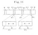
Fig. 11 is a schematic diagram showing an arrangement
of various areas in the optical disc medium 6 of the third
embodiment. Referring to Fig. 11, the arrangement of
various areas will be described below. The optical disc
medium 6 in the third embodiment includes the data area
23 in the outer side of the user data lead-in area 28 in
the system area 22.
-
As shown in Fig. 11, the data area 23 includes a
plurality of the bordered areas 31-1 to 31-3 and the border
areas 32-1 to 32-3. The data area with three bordered
areas and three border areas is explained here, however
the present invention cannot be limited to that. The
border area 32-1 includes a border-out area 37-1 and a
border-in area 35-2. The border area 32-2 includes a
border-out area 37-2 and a border-in area 35-3. The border
area 32-3 includes a border-out area 37-3. In each
border-out area, a border-out data is recorded.
-
That is, the bordered area 31-1, which is on the most
inner side, is sandwiched by the user data lead-in area
28 and the border-out area 37-1. The bordered area 31-2
is sandwiched by the border-in area 35-2 and a border-out
area 37-2. The bordered area 31-3 is sandwiched by
the border-in area 35-3 and the border-out area 37-3.
-
The border-out area 37 includes an area 61 and an area
62. Record control data are recorded in the area 61. The
record control data are used when the user data are recorded
and played. The dummy data are recorded in the area 62.
In the playback-only apparatus, it is not possible to play
data if all recorded areas are not sequential. The area
62, where the dummy data is recorded, is an available area
such as a reservation area. However, the dummy data are
recorded in the area 62 so that the playback-only apparatus
for DVD-ROM medium can play a write-once optical medium.
For instance, "00" is used as the user data for a
conventional DVD-R.
-
In the third embodiment, different kinds of the dummy
data are used according to whether the finalization is
executed or not. In order to maintain a compatibility with
the conventional method, "00" is used for the dummy data
in the case of no finalization as well as the conventional
method. "FF" is used (hexadecimal number (notation)) for
the dummy data in the case that the finalization is executed
in the present invention. However, data pattern is not
limited to this. For example, "FF" may be applied to the
no finalization, and "00" may be applied to the
finalization. Also, the pattern composed of plural octets
may be applied to the no finalization and the finalization.
-
Therefore, since the recorded data are continued to
the bordered area 31-2, the dummy data "00" is recorded
in the area 62 of the border-out area 37-1. Similarly,
since the recorded data are continued to the bordered area
31-3, the dummy data "00" is recorded in the area 62 of
the border-out area 37-2. On the other hand, since the
recorded data are finished at the bordered area 31-3 which
is in the outer side of the optical disc medium 6, the dummy
data "FF" is recorded in the area 62 of the border-out area
37-3.
-
In the playing of the data that are recorded above
in the optical disk medium 6, by reading the dummy data
in the border-out area, it is possible to recognize whether
the border-out area is an area that is followed by the
bordered area in the outer side and is not finalized, or
the border-out area is in the most outer side and is
finalized. If the border-out area is in the most outer
side and is not finalized, the user data lead-out area is
not necessary for the outer side. That is, it is possible
to omit the user data lead-out area, which is
conventionally provided in the most outer side of the
optical disk medium 6 so far. Therefore, the processing
time to record the user data lead-out data can be reduced,
and the record time can be shortened.
-
Next, an operation of the third embodiment will be
described with reference to attached drawings. Fig. 12
is a flowchart showing a recording operation of the third
embodiment. In this recording operation, the optical disc
apparatus 4 records the user data to the optical disk medium
6. The optical disc apparatus 4 (CPU 10) sets an area for
recording data in the optical disk medium 6 in response
to the instruction to record the user data in the optical
disk medium 6. In the case that the instruction for
recording additional user data has been received after the
user data has been recorded in the range of the bordered
area 31-1, the user data is already recorded in the range
of the border-out area 37-1. Therefore, as the start
address of the border-in area that the format data is
determined, optical disc apparatus 4 (CPU 10) sets an end
address to clarify the range of the border-in area 35-2.
After the range of the border-in area 35-2 is
determined, the start address of the bordered area 31-2
adjacent to the border-in area 35-2 is determined. Then,
it is possible to record the user data (step S51).
-
Setting the area to record the user data, the optical
disc apparatus 4 (CPU 10) records the user data in the
bordered area 31-2 (step S52). For example of the data
recording step, the CPU 10 controls the encoder 16 to encode
the data if the data are the user data, and controls disc
controller 14, which controls the rotation driving system
20 and the access section 12, to records the data in the
predetermined area. Same step may be used for recording
of any data in the optical disc medium 6.
-
After the user data are recorded, the optical disc
apparatus 4 (CPU 10) receives an instruction from the host
apparatus 2 whether or not additional user data exist to
be recorded in the optical disk medium 6 after the recording
of all the user data (step S53).
-
In the case that the additional user data exist (step
S53: NO), the optical disc apparatus 4 (CPU 10) records
the border-out data in the bordered area 32-2 following
the bordered area 31-2 with the recorded user data. At
this time, the dummy data to be recorded in the area 62
of the border-out area 37-2 is set as "00" (step S55).
-
Since the border-out data is recorded in the
border-out area 37-2, and the recording position of the
border area 32-2 is defined. Therefore, the position of
the following border area for recording the format data
is determined. Thus, the format data to be recorded in
the border-in area 35-2 is determined, and the optical disc
apparatus4 (CPU 10) records the format data in the
border-in area 35-2 (step S56). The optical disc
apparatus4 (CPU 10) receives an instruction from the host
apparatus 2 to record the following user data, and then
the operation is repeated from the step S51.
-
In the step S52, when the last user data of the optical
disk medium 6 is recorded in the bordered area 31-3, the
optical disc apparatus 4 (CPU 10) receives an instruction
from the host apparatus 2 whether or not additional user
data exist to be recorded in the optical disk medium 6 after
the recording of all the user data (step S53). In the
case that the additional user data to record in the optical
disk medium 6 does not exist after all the user data is
recorded (step S53: YES), the optical disc apparatus 4 (CPU
10) records the border-out data in the area following the
bordered area 31-3 in which the user data is recorded. At
this time, the dummy data recorded in the area 62 of the
border-out area 37-3 is set as "FF" (step S58).
-
To determine the format data, the optical disc
apparatus 4 (CPU 10) records the format data in the
border-in area 35-3. Moreover, the optical disc apparatus
4 (CPU 10) executes processing necessary for finalization
to the unrecorded part of the system area 22, such as
recording a dummy data and the like. Then, the record of
the user data in the optical disk medium 6 is completed
(step S59). In this example, the border-in data is
recorded after the recording the border-out data. However,
it is possible to record the border-out data after
recording the border-in data.
-
Fig. 13 is a flowchart showing a playing operation
of the third embodiment. In this playing operation, the
optical disc apparatus 4 plays the user data on the optical
disk medium 6. The user data were recorded in the optical
disk medium 6 as mentioned above. In the playing of the
user data recorded in the optical disk medium 6, the optical
disc apparatus 4 (CPU 10) firstly accesses the user data
lead-in area and the border-in area in order to read the
format data recorded in the user data lead-in or the
border-in (step S61). For example of the data reading step,
the CPU 10 controls the disc controller 14, which controls
the rotation driving system 20 and the access section 12,
to reads the data in the predetermined area.
-
The optical disc apparatus 4 (CPU 10) accesses the
bordered area 31, where the user data are recorded to be
played based on the read format data, and plays the user
data (the step S63) . For example of the user data playing
step, the CPU 10 controls disc controller 14, which
controls the rotation driving system 20 and the access
section 12, to reads the user data in the predetermined
area, and controls the decoder 18 to decode and play the
user data.
-
Finishing the playing of the user data in the bordered
area 31, the optical disc apparatus 4 (CPU 10) accesses
the border-out area 37 to read the dummy data in the area
66 in the border-out area 37 (step S65).
-
When the read dummy data is "00" (step S67: "00"),
the bordered area exists, where additional user data is
recorded. For instance, as for the border-out area 37-2,
the bordered area 31-3 exists, and thus the dummy data is
"00" . In this case, the operation returns to the step S61
and the optical disc apparatus 4 (CPU 10) plays the
following user data of the bordered area 31.
-
When the read dummy data is "FF" (step S67: "FF"),
the bordered area does not exist, where additional user
data is recorded. For instance, as for the border-out area
37-3, there is no bordered area following the border area
32-3. That is, the border area 32-3 followed by the
bordered area 31-3 from which the user data has been played,
is the last area recorded in the optical disk medium 6.
In this case, the playing of the user data is completed.
-
In this way, the dummy data recorded in the area 62
of the border-out area 37 is changed based on whether the
finalization is executed or not. Therefore, the border
area 32-3 (the border-out area 37-3) which is in the most
outer side can be used as both the border-out area and the
user data lead-out area simultaneously. Then, it is not
necessary to provide the user data lead-out area
individually, and the record area can be effectively used.
Moreover, it is possible to reduce the amount of the data
to be recorded in the optical disk medium 6, and the record
time can be shortened.
-
The first to third embodiments of the present
invention have been explained hereof. It should be noted
that it is possible to combine at least two of these
embodiments.
-
In the conventional optical disk medium 6, the
lead-out area that shows the completion of the record is
provided following the border area 32-3. This lead-out
area is an area that shows the end of the optical disk medium
6. When the optical disc apparatus 4 (CPU 10) detects the
end of the optical disk medium 6 at the playing process,
the optical disc apparatus 4 recognizes the end of the whole
optical disk medium 6. Conventionally, in order to
maintain compatibility with ROM media, many lead-out areas
as guard areas are provided based on a specification of
the ROM. In the DVD-R, the user data lead-out area
occupies the 500 µm or more width in the radial direction
of the optical disk medium. On the other hand, the width
in the radial direction of the border area can be set less
than 500 µm.
-
According to the three embodiments of the present
invention, the area combination flag 42 in the border-in
area 35-3, the area type 55 in the border-out area 37-3,
or the dummy data in the border-out area 37-3 (finalization
identifying data) show that the optical disk medium 6 is
finalized by the record of the border area 32-3. Therefore,
the lead-out area is not necessary, which is to identify
the end of the optical disk medium. As a result, the
recording processing for the lead-out area do not need to
be executed, and the time for the finalization can be
shortened.
-
Here, to maintain the compatibility with an old
version's optical disc medium, the border area in the most
outer side such as the border area 32-3 may have data
similar to the lead-out area. Even in this case, by using
the technique of the above embodiments, the data amount
of the border area in the most outer side can be reduced.
Therefore, the time for the finalization can be shortened.
-
It is apparent that the present invention is not
limited to the above embodiment, that may be modified and
changed without departing form the scope and spirit of the
invention.