EP1591898A2 - Dynamic control system diagnostics for modular architectures - Google Patents
Dynamic control system diagnostics for modular architectures Download PDFInfo
- Publication number
- EP1591898A2 EP1591898A2 EP05251569A EP05251569A EP1591898A2 EP 1591898 A2 EP1591898 A2 EP 1591898A2 EP 05251569 A EP05251569 A EP 05251569A EP 05251569 A EP05251569 A EP 05251569A EP 1591898 A2 EP1591898 A2 EP 1591898A2
- Authority
- EP
- European Patent Office
- Prior art keywords
- module
- component
- components
- modular
- diagnostic
- Prior art date
- Legal status (The legal status is an assumption and is not a legal conclusion. Google has not performed a legal analysis and makes no representation as to the accuracy of the status listed.)
- Granted
Links
Images


Classifications
-
- G—PHYSICS
- G06—COMPUTING OR CALCULATING; COUNTING
- G06F—ELECTRIC DIGITAL DATA PROCESSING
- G06F11/00—Error detection; Error correction; Monitoring
- G06F11/07—Responding to the occurrence of a fault, e.g. fault tolerance
- G06F11/0703—Error or fault processing not based on redundancy, i.e. by taking additional measures to deal with the error or fault not making use of redundancy in operation, in hardware, or in data representation
- G06F11/0766—Error or fault reporting or storing
- G06F11/0769—Readable error formats, e.g. cross-platform generic formats, human understandable formats
-
- G—PHYSICS
- G05—CONTROLLING; REGULATING
- G05B—CONTROL OR REGULATING SYSTEMS IN GENERAL; FUNCTIONAL ELEMENTS OF SUCH SYSTEMS; MONITORING OR TESTING ARRANGEMENTS FOR SUCH SYSTEMS OR ELEMENTS
- G05B23/00—Testing or monitoring of control systems or parts thereof
- G05B23/02—Electric testing or monitoring
- G05B23/0205—Electric testing or monitoring by means of a monitoring system capable of detecting and responding to faults
- G05B23/0259—Electric testing or monitoring by means of a monitoring system capable of detecting and responding to faults characterized by the response to fault detection
- G05B23/0267—Fault communication, e.g. human machine interface [HMI]
-
- G—PHYSICS
- G06—COMPUTING OR CALCULATING; COUNTING
- G06F—ELECTRIC DIGITAL DATA PROCESSING
- G06F11/00—Error detection; Error correction; Monitoring
- G06F11/07—Responding to the occurrence of a fault, e.g. fault tolerance
- G06F11/0703—Error or fault processing not based on redundancy, i.e. by taking additional measures to deal with the error or fault not making use of redundancy in operation, in hardware, or in data representation
- G06F11/0706—Error or fault processing not based on redundancy, i.e. by taking additional measures to deal with the error or fault not making use of redundancy in operation, in hardware, or in data representation the processing taking place on a specific hardware platform or in a specific software environment
- G06F11/0733—Error or fault processing not based on redundancy, i.e. by taking additional measures to deal with the error or fault not making use of redundancy in operation, in hardware, or in data representation the processing taking place on a specific hardware platform or in a specific software environment in a data processing system embedded in an image processing device, e.g. printer, facsimile, scanner
Definitions
- the present invention generally relates to the automated diagnostics of electrical, mechanical and electromechanical systems and devices. More specifically, the present invention relates to improved diagnostics and troubleshooting for systems and devices which accommodate modular add-ons.
- Prior art approaches to modular system diagnostics are typified by the Xerox 5090/family of products, where the electrical control information for all of the modular components anticipated to be connected in the system are pre-stored prior to the core component or components leaving the factory.
- a hierarchical display illustrates the electrical control topology of each of the modules coupled to the system that can be used as an aid to indicate fault conditions in any of the components of a module.
- This is essentially a closed architecture approach to document reproduction systems, in that either only predefined modular components are to be attached to the system, or when other modular components are connected to the system (e.g., manufactured or supplied by separate entities that are unrelated to the manufacturer or supplier of the core system components), there is no possibility of either running diagnostics or displaying diagnostic results without modifying the standard user interface.
- the pre-sent invention provides a diagnostic method for performing diagnostics in a system adapted to receive modular components, the method at least including: a) graphically displaying a hierarchical representation of system components and modular add-on components; b) detecting the modular components coupled to the system; c) dynamically requesting and receiving the electrical control topology and fault status of each coupled modular component; and d) dynamically integrating the electrical control topology and fault status of each coupled modular component into the display of a).
- the present invention also provides a diagnostic method for diagnosing post-manufacture modular add-on components coupled to a system, the method at least including: a) dynamically retrieving control system topology information not stored at the time of manufacture pertaining to a module chosen for a system graphical display; b) via each module, generating diagnostic information about the components of a module; c) dynamically retrieving module diagnostic information pertaining to a module chosen for a system graphical display; d) hierarchically displaying the component levels of the module chosen for graphical display; e) providing a link between the component levels; and f) indicating the diagnostic status of a displayed component level.
- teachings of the present invention can be applied to any number of electrical and electromechanical systems and machines, such as high speed, higher capacity photocopiers and printers, for example.
- the system 100 in Figure 1 is a modular document reproduction system with an open architecture capability.
- the system core 110 can contain, for example, components such as a print engine 150 for performing electrostatic image reproduction, a power supply 130, a control unit 134, memory 140, and a user interface 120, serving both to communicate with a user and graphically and textually display status and diagnostic information about the components coupled to the system.
- Many module types are envisioned, including for example, a feeder module 170 for feeding documents to the main unit comprising the print engine, a stacker module 180 for stacking and sorting document copies, and other modules such as the one 190 symbolically shown for other document finishing operations (e.g., binding).
- the modules can be connected via standard or proprietary buses without departing from the scope of the present invention.
- a display (not shown) for displaying the electrical control topology of all of the connected modules, as well as the status of each module, and any fault conditions of module components.
- the terms "peripheral,” “computer peripheral,” and “peripheral device” refer, for example, to any apparatus that can interface with a computer, whether it be a conventional computer peripheral device such as a printer, or other devices such as appliances with computer interfaces. Diagnostic routines for each module can be initiated and controlled either by the user interface 120, or a Program and Systems Information Protocol (PSIP) 194 or a Personal Service Workstation (PSW) 198 connected to the system core 110.
- PSIP Program and Systems Information Protocol
- PSW Personal Service Workstation
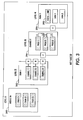
- the display 205 in Figure 2 graphically illustrates an example of what a system user might see showing the modules attached, along with their current status (e.g., functioning properly, malfunctioning, or indeterminate because of communication or power loss problems).
- the graphical display 205 shows the feeder module 270 connected to the print engine 250, which is connected to a binding module 290 (for binding copies), which in turn is connected to a stacker module 280 for outputting (e.g., stacking and/or sorting) copies of a print job.
- the present invention hierarchically displays the electrical control levels of each module connected to the system with the highest level displayed by default. Except for the highest level, each level has components that are electrically controlled by the level immediately higher than the level in question, and that same level electrically controls components in any lower immediate level.
- a color-coding scheme is used in the preferred embodiment to indicate when modules experience a fault condition in any of their components.
- the first level representation 280 of the hierarchical display of the stacker module illustrates by the color (e.g., green) of its highest level that the stacker is functioning normally.
- the module 280 has three separate “chains” in the representation, representing three separate portions of the module.
- each chain has multiple "channels," further representing refinements.
- each channel has multiple printed wiring board assemblies (PWBAs) representing individual elements.
- PWBAs printed wiring board assemblies
- the fourth level 286 of the representation is that of a more detailed view of a PWBA.
- the status box 288 of the example PWBA 286 shows that the PWBA is operating normally (Status - "OK").
- the representation in Figure 5 shows a PWBA, and thus a module in a faulted condition.
- the color scheme of present invention indicates by a color such as yellow that there is a fault condition in Chain 1, and that there is further a fault condition in Channel 1.
- the color red indicates that PWBA 1 is faulted. Additionally, the color red is used to show in the fourth level 286 that the status (box 288) of PWBA 1 is faulted.
- a module when shown to have a component in a fault condition, the user can "double click" on the highest level, and continue until he/she reaches the level indicated to have a malfunctioning component. That level will contain a display such as the one 286 in Figure 5 showing the affected component or components, and the nature of the fault.
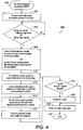
- the automated diagnostic/troubleshooting program 400 of the present invention is illustrated in the flowchart of Figure 4. While there are a number of possible starting points that are appropriate, given the teachings of the present invention, one possible starting step 402 graphically displays icons of the system modular components. In case new modules have been connected since the last diagnostic program, the user interface ascertains the modules that are connected to the system and updates the display (Step 404).
- Step 406 determines whether the user has invoked a diagnostic operation, or alternatively whether it is time for a scheduled periodic diagnostic operation. If either condition exists, the algorithm advances to Step 408. Otherwise, the algorithm remains at Step 406.
- Step 408 the user interface requests the name and status of each component of the targeted module for the case where the user has invoked a diagnostic operation for a particular module (Case A in Figure 4).
- a diagnostic operation for a particular module
- the user interface requests the name and status of each component for every module connected to the system.
- the polled module or modules respond to the user interface by transmitting the requested information in Step 410.
- any fault conditions in a module are indicated by a special color code of the highest level in the graphical display. For example, if the icon of module is display in red as opposed to blue or green, a fault condition exists in one of the module's components. To determine where the fault condition exists in the module, the user "doubleclicks" a pointing device to access succeeding levels of the module until the electrical level with the faulted component is reached (Step 414). The specific fault component and fault conditions are displayed in Step 416 (See also Figure 3).
- Step 418 determines if the status of a faulted component has changed since the last operation. If so, the count is updated and displayed (Steps 420 and 422). If not, the existing count is displayed (Step 422). The algorithm ends at Step 424.
- the functions in the diagnostic and display algorithm 400 carried out by the user interface can be carried out by other means such as a PSIP or PSW (see supra).
Landscapes
- Engineering & Computer Science (AREA)
- Theoretical Computer Science (AREA)
- Physics & Mathematics (AREA)
- General Physics & Mathematics (AREA)
- Quality & Reliability (AREA)
- General Engineering & Computer Science (AREA)
- Computer Vision & Pattern Recognition (AREA)
- Automation & Control Theory (AREA)
- Human Computer Interaction (AREA)
- Debugging And Monitoring (AREA)
- Test And Diagnosis Of Digital Computers (AREA)
- Accessory Devices And Overall Control Thereof (AREA)
- Control Or Security For Electrophotography (AREA)
- Tests Of Electronic Circuits (AREA)
- Digital Computer Display Output (AREA)
Abstract
Description
Claims (8)
- A diagnostic method for performing diagnostics in a system adapted to receive modular components comprising:a) graphically displaying a hierarchical representation of system components and modular add-on components;b) detecting the modular components coupled to the system;c) dynamically requesting and receiving the electrical control topology and fault status of each coupled modular component; andd) dynamically integrating the electrical control topology and fault status of each coupled modular component into the display of a).
- The method of Claim 1, further comprising:automatically performing c) and d) at predefined intervals.
- A diagnostic method for diagnosing post-manufacture modular add-on components coupled to a system, said method comprising:a) dynamically retrieving control system topology information not stored at the time of manufacture pertaining to a module chosen for a system graphical display;b) via each module, generating diagnostic information about the components of a module;c) dynamically retrieving module diagnostic information pertaining to a module chosen for a system graphical display;d) hierarchically displaying the component levels of the module chosen for graphical display;e) providing a link between the component levels; andf) indicating the diagnostic status of a displayed component level.
- The method of Claim 3, further comprising:automatically performing a) and f) at predefined intervals.
- The method of any of the preceding claims, wherein a fault condition in a component of a module is indicated in the highest hierarchical level pertaining to the module.
- The method of any of the preceding claims, wherein a fault condition in a component of a module is indicated by color-coded indicia in the highest hierarchical level pertaining to the module.
- The method according to any of the preceding claims, wherein said system is an image reproduction system.
- The method of any of the preceding claims, further comprising:maintaining a count of each time the fault status of a component in a module changes; anddisplaying said count.
Applications Claiming Priority (2)
| Application Number | Priority Date | Filing Date | Title |
|---|---|---|---|
| US806007 | 2004-03-22 | ||
| US10/806,007 US7249283B2 (en) | 2004-03-22 | 2004-03-22 | Dynamic control system diagnostics for modular architectures |
Publications (3)
| Publication Number | Publication Date |
|---|---|
| EP1591898A2 true EP1591898A2 (en) | 2005-11-02 |
| EP1591898A3 EP1591898A3 (en) | 2007-01-17 |
| EP1591898B1 EP1591898B1 (en) | 2018-09-05 |
Family
ID=34940582
Family Applications (1)
| Application Number | Title | Priority Date | Filing Date |
|---|---|---|---|
| EP05251569.9A Ceased EP1591898B1 (en) | 2004-03-22 | 2005-03-16 | Dynamic control system diagnostics for modular architectures |
Country Status (4)
| Country | Link |
|---|---|
| US (1) | US7249283B2 (en) |
| EP (1) | EP1591898B1 (en) |
| JP (1) | JP4822721B2 (en) |
| CA (1) | CA2500701C (en) |
Families Citing this family (13)
| Publication number | Priority date | Publication date | Assignee | Title |
|---|---|---|---|---|
| JP4039276B2 (en) * | 2003-03-05 | 2008-01-30 | 富士ゼロックス株式会社 | Service processing system and program |
| US7299385B2 (en) * | 2004-07-28 | 2007-11-20 | Hewlett-Packard Development Company, L.P. | Managing a fault tolerant system |
| US20070006050A1 (en) * | 2005-06-30 | 2007-01-04 | Xerox Corporation | Automatic notification of applicable bulletins and tags based on fault analysis |
| US7546493B2 (en) * | 2006-04-28 | 2009-06-09 | Siemens Aktiengesellschaft | Method for responding to errors occurring during operation of a networked medical system |
| US7770052B2 (en) * | 2006-05-18 | 2010-08-03 | The Boeing Company | Collaborative web-based airplane level failure effects analysis tool |
| US20080059838A1 (en) * | 2006-09-01 | 2008-03-06 | Melman Phillipe A | Apparatus And Method For Performing Failure Diagnostic Testing of Electronic Equipment |
| US8022823B2 (en) * | 2008-06-30 | 2011-09-20 | Xerox Corporation | Serendipitous repair of shared device |
| JP5743391B2 (en) * | 2009-09-24 | 2015-07-01 | キヤノン株式会社 | Control device and image forming apparatus |
| JP2013045200A (en) * | 2011-08-23 | 2013-03-04 | Kyocera Document Solutions Inc | Support service system, electronic apparatus, and image forming device |
| JP5759853B2 (en) * | 2011-09-29 | 2015-08-05 | 株式会社オプティム | Diagnostic method, diagnostic code generation system, and diagnostic code generation system program |
| CN103684816B (en) * | 2012-09-04 | 2017-12-22 | 华为技术有限公司 | resource information display method and device |
| US11416064B2 (en) | 2017-05-17 | 2022-08-16 | Siemens Healthcare Diagnostics Inc. | Alerts with augmented reality |
| US20240289065A1 (en) | 2023-02-27 | 2024-08-29 | Fujifilm Business Innovation Corp. | Information processing system and non-transitory computer readable medium |
Family Cites Families (40)
| Publication number | Priority date | Publication date | Assignee | Title |
|---|---|---|---|---|
| US4592053A (en) * | 1982-02-19 | 1986-05-27 | Omron Tateisi Electronics Co. | Programmable controller |
| JPS6154509A (en) * | 1984-08-23 | 1986-03-18 | Meidensha Electric Mfg Co Ltd | Fault display device for process equipment |
| US4742483A (en) * | 1985-05-14 | 1988-05-03 | Minolta Camera Company, Ltd. | Laser printer maintenance system |
| US5200958A (en) * | 1990-09-28 | 1993-04-06 | Xerox Corporation | Method and apparatus for recording and diagnosing faults in an electronic reprographic printing system |
| JP3240162B2 (en) * | 1991-08-23 | 2001-12-17 | 株式会社日立製作所 | Screen display method and man-machine interface device in process control system |
| TW272270B (en) * | 1992-08-28 | 1996-03-11 | Compaq Computer Corp | |
| JPH06110508A (en) * | 1992-09-28 | 1994-04-22 | Nissan Motor Co Ltd | Production control equipment |
| JP3362940B2 (en) * | 1993-12-22 | 2003-01-07 | ソニー株式会社 | Monitoring device |
| DE4432237A1 (en) * | 1994-06-08 | 1995-12-14 | Orenstein & Koppel Ag | Control for mobile work machines |
| US5533193A (en) * | 1994-06-24 | 1996-07-02 | Xerox Corporation | Method of saving machine fault information including transferring said information to another memory when an occurrence of predetermined events or faults of a reproduction machine is recognized |
| JPH09102970A (en) * | 1995-10-05 | 1997-04-15 | Sony Corp | Video and audio equipment error monitoring system |
| US5694528A (en) * | 1995-11-22 | 1997-12-02 | Xerox Corporation | Apparatus and method for diagnosing printing machine operation with facsimile transmitted dialog screens |
| JPH1090355A (en) * | 1996-09-12 | 1998-04-10 | Ricoh Co Ltd | Image forming device |
| US6335927B1 (en) * | 1996-11-18 | 2002-01-01 | Mci Communications Corporation | System and method for providing requested quality of service in a hybrid network |
| US7444394B2 (en) * | 1997-02-03 | 2008-10-28 | Canon Kabushiki Kaisha | Network data base control device and method thereof |
| IL121348A0 (en) * | 1997-07-21 | 1998-04-05 | Bio Rad Lab Israel Inc | System and method for device monitoring |
| JP3545179B2 (en) * | 1997-10-31 | 2004-07-21 | シャープ株式会社 | Image forming system |
| US6049764A (en) * | 1997-11-12 | 2000-04-11 | City Of Hope | Method and system for real-time control of analytical and diagnostic instruments |
| US6247077B1 (en) * | 1998-02-06 | 2001-06-12 | Ncr Corporation | Highly-scalable parallel processing computer system architecture |
| US6353899B1 (en) * | 1998-04-10 | 2002-03-05 | Xerox Corporation | Fault management system for a multifunctional printing machine |
| US6628304B2 (en) * | 1998-12-09 | 2003-09-30 | Cisco Technology, Inc. | Method and apparatus providing a graphical user interface for representing and navigating hierarchical networks |
| US6477572B1 (en) * | 1998-12-17 | 2002-11-05 | International Business Machines Corporation | Method for displaying a network topology for a task deployment service |
| US6728214B1 (en) * | 1999-07-28 | 2004-04-27 | Lucent Technologies Inc. | Testing of network routers under given routing protocols |
| WO2001055806A1 (en) * | 2000-01-29 | 2001-08-02 | Abb Research Ltd. | Method for automatic fault tree synthesis |
| US6615372B1 (en) * | 2000-02-22 | 2003-09-02 | Ricoh Company, Ltd. | Method of retrieving and displaying problematic information about a printer prior to a print job being printed on the printer |
| US6691249B1 (en) * | 2000-03-22 | 2004-02-10 | Agilent Technologies, Inc. | Probabilistic diagnosis, in particular for embedded and remote applications |
| US7051243B2 (en) * | 2002-04-30 | 2006-05-23 | Sun Microsystems, Inc. | Rules-based configuration problem detection |
| US6782345B1 (en) * | 2000-10-03 | 2004-08-24 | Xerox Corporation | Systems and methods for diagnosing electronic systems |
| US7305485B2 (en) * | 2000-12-15 | 2007-12-04 | International Business Machines Corporation | Method and system for network management with per-endpoint adaptive data communication based on application life cycle |
| US7073093B2 (en) * | 2001-05-15 | 2006-07-04 | Hewlett-Packard Development Company, L.P. | Helpdesk system and method |
| US6782495B2 (en) * | 2001-06-19 | 2004-08-24 | Xerox Corporation | Method for analyzing printer faults |
| US6813587B2 (en) * | 2001-06-22 | 2004-11-02 | Invensys Systems, Inc. | Remotely monitoring/diagnosing distributed components of a supervisory process control and manufacturing information application from a central location |
| US20030009553A1 (en) * | 2001-06-29 | 2003-01-09 | International Business Machines Corporation | Method and system for network management with adaptive queue management |
| JP4113352B2 (en) * | 2001-10-31 | 2008-07-09 | 株式会社日立製作所 | Storage resource operation management method in storage network |
| JP3876692B2 (en) * | 2001-11-13 | 2007-02-07 | 株式会社日立製作所 | Network system failure analysis support method and method |
| DE10204826A1 (en) | 2002-02-06 | 2003-08-14 | Siemens Ag | System and method for analyzing a network and / or generating the topology of a network |
| ATE253745T1 (en) * | 2002-03-18 | 2003-11-15 | Ubs Ag | SECURE USER AND DATA AUTHENTICATION OVER A COMMUNICATIONS NETWORK |
| US7149936B2 (en) * | 2002-09-30 | 2006-12-12 | Sharp Laboratories Of America, Inc. | Interactive multimedia for remote diagnostics and maintenance of a multifunctional peripheral |
| CN1527232A (en) * | 2002-10-16 | 2004-09-08 | �ֹ��� | Method ad apparatus for realizing distribution preset service, automatic supply maintenance and irrelevant service implementation with equipment |
| US20050108375A1 (en) * | 2003-11-13 | 2005-05-19 | Michele Hallak-Stamler | Method and graphical user interface for managing and configuring multiple clusters of virtualization switches |
-
2004
- 2004-03-22 US US10/806,007 patent/US7249283B2/en not_active Expired - Lifetime
-
2005
- 2005-03-14 CA CA2500701A patent/CA2500701C/en not_active Expired - Fee Related
- 2005-03-16 EP EP05251569.9A patent/EP1591898B1/en not_active Ceased
- 2005-03-18 JP JP2005078479A patent/JP4822721B2/en not_active Expired - Fee Related
Also Published As
| Publication number | Publication date |
|---|---|
| JP4822721B2 (en) | 2011-11-24 |
| JP2005275406A (en) | 2005-10-06 |
| US7249283B2 (en) | 2007-07-24 |
| CA2500701C (en) | 2010-02-16 |
| US20050210330A1 (en) | 2005-09-22 |
| EP1591898B1 (en) | 2018-09-05 |
| CA2500701A1 (en) | 2005-09-22 |
| EP1591898A3 (en) | 2007-01-17 |
Similar Documents
| Publication | Publication Date | Title |
|---|---|---|
| EP1591898B1 (en) | Dynamic control system diagnostics for modular architectures | |
| JP4878674B2 (en) | Hybrid diagnostic system for real-time diagnosis of electronic systems | |
| US6507765B1 (en) | Computer integrated manufacturing control and information system | |
| US7421371B2 (en) | Automated performance analysis and failure remediation | |
| DE10154534B4 (en) | Integrated alarm display in a process control network | |
| US6947675B2 (en) | Remote maintenance and diagnosis of office or domestic appliances | |
| US6327516B1 (en) | Operation terminal and remote operation system for a robot | |
| CA2092880C (en) | Monitoring method for a technical process | |
| GB2247540A (en) | Controlling and communicating between electronic devices | |
| CN102473071A (en) | Information processing apparatus, information processing method and program | |
| US10346103B2 (en) | Method to configure a control device for a production system | |
| US20160170686A1 (en) | System and method for monitoring a production system | |
| US20090284387A1 (en) | Customizable indicator light | |
| US7664555B2 (en) | Operation target identification system | |
| US20190281120A1 (en) | Method for designing data and operation management system for the manufacturing, operation and maintenance of ip door controllers | |
| WO2004038513A2 (en) | Graphical user surface and method for indicating a malfunction state of an electrophotographic printing or copying system | |
| US6381712B1 (en) | Method and apparatus for providing an error messaging system | |
| CN105099750A (en) | Failure information management system and failure information management apparatus | |
| US8040230B2 (en) | Alarm control apparatus | |
| US11422756B1 (en) | System for monitoring and recovering functions of printing devices and a managing server | |
| DE10348330B4 (en) | A method of use in a printing device, remote test website and computer readable medium | |
| JPH11120031A (en) | Field device status display device | |
| JP3767816B2 (en) | Uninterruptible power supply system monitoring method, uninterruptible power supply system, uninterruptible power supply, and switchboard | |
| JP7554712B2 (en) | Elevator maintenance support system and elevator maintenance support method | |
| DE10250186B4 (en) | System and method for remote maintenance, remote configuration and / or remote control of a printing or copying system |
Legal Events
| Date | Code | Title | Description |
|---|---|---|---|
| PUAI | Public reference made under article 153(3) epc to a published international application that has entered the european phase |
Free format text: ORIGINAL CODE: 0009012 |
|
| AK | Designated contracting states |
Kind code of ref document: A2 Designated state(s): AT BE BG CH CY CZ DE DK EE ES FI FR GB GR HU IE IS IT LI LT LU MC NL PL PT RO SE SI SK TR |
|
| AX | Request for extension of the european patent |
Extension state: AL BA HR LV MK YU |
|
| PUAL | Search report despatched |
Free format text: ORIGINAL CODE: 0009013 |
|
| AK | Designated contracting states |
Kind code of ref document: A3 Designated state(s): AT BE BG CH CY CZ DE DK EE ES FI FR GB GR HU IE IS IT LI LT LU MC NL PL PT RO SE SI SK TR |
|
| AX | Request for extension of the european patent |
Extension state: AL BA HR LV MK YU |
|
| 17P | Request for examination filed |
Effective date: 20070717 |
|
| AKX | Designation fees paid |
Designated state(s): DE FR GB |
|
| 17Q | First examination report despatched |
Effective date: 20151102 |
|
| REG | Reference to a national code |
Ref country code: DE Ref legal event code: R079 Ref document number: 602005054541 Country of ref document: DE Free format text: PREVIOUS MAIN CLASS: G06F0011070000 Ipc: G05B0023020000 |
|
| GRAP | Despatch of communication of intention to grant a patent |
Free format text: ORIGINAL CODE: EPIDOSNIGR1 |
|
| RIC1 | Information provided on ipc code assigned before grant |
Ipc: G05B 23/02 20060101AFI20180221BHEP Ipc: G06F 11/07 20060101ALI20180221BHEP |
|
| INTG | Intention to grant announced |
Effective date: 20180326 |
|
| RIN1 | Information on inventor provided before grant (corrected) |
Inventor name: PLATTETER, DALE T. |
|
| GRAS | Grant fee paid |
Free format text: ORIGINAL CODE: EPIDOSNIGR3 |
|
| GRAA | (expected) grant |
Free format text: ORIGINAL CODE: 0009210 |
|
| AK | Designated contracting states |
Kind code of ref document: B1 Designated state(s): DE FR GB |
|
| REG | Reference to a national code |
Ref country code: GB Ref legal event code: FG4D |
|
| REG | Reference to a national code |
Ref country code: DE Ref legal event code: R096 Ref document number: 602005054541 Country of ref document: DE |
|
| RIC2 | Information provided on ipc code assigned after grant |
Ipc: G05B 23/02 20060101AFI20180221BHEP Ipc: G06F 11/07 20060101ALI20180221BHEP |
|
| REG | Reference to a national code |
Ref country code: DE Ref legal event code: R097 Ref document number: 602005054541 Country of ref document: DE |
|
| PLBE | No opposition filed within time limit |
Free format text: ORIGINAL CODE: 0009261 |
|
| STAA | Information on the status of an ep patent application or granted ep patent |
Free format text: STATUS: NO OPPOSITION FILED WITHIN TIME LIMIT |
|
| 26N | No opposition filed |
Effective date: 20190606 |
|
| PGFP | Annual fee paid to national office [announced via postgrant information from national office to epo] |
Ref country code: DE Payment date: 20200218 Year of fee payment: 16 Ref country code: GB Payment date: 20200221 Year of fee payment: 16 |
|
| PGFP | Annual fee paid to national office [announced via postgrant information from national office to epo] |
Ref country code: FR Payment date: 20200220 Year of fee payment: 16 |
|
| REG | Reference to a national code |
Ref country code: DE Ref legal event code: R119 Ref document number: 602005054541 Country of ref document: DE |
|
| GBPC | Gb: european patent ceased through non-payment of renewal fee |
Effective date: 20210316 |
|
| PG25 | Lapsed in a contracting state [announced via postgrant information from national office to epo] |
Ref country code: FR Free format text: LAPSE BECAUSE OF NON-PAYMENT OF DUE FEES Effective date: 20210331 Ref country code: GB Free format text: LAPSE BECAUSE OF NON-PAYMENT OF DUE FEES Effective date: 20210316 Ref country code: DE Free format text: LAPSE BECAUSE OF NON-PAYMENT OF DUE FEES Effective date: 20211001 |