EP1591818A1 - Image pickup device and mobile terminal device using the image pickup device - Google Patents
Image pickup device and mobile terminal device using the image pickup device Download PDFInfo
- Publication number
- EP1591818A1 EP1591818A1 EP04707309A EP04707309A EP1591818A1 EP 1591818 A1 EP1591818 A1 EP 1591818A1 EP 04707309 A EP04707309 A EP 04707309A EP 04707309 A EP04707309 A EP 04707309A EP 1591818 A1 EP1591818 A1 EP 1591818A1
- Authority
- EP
- European Patent Office
- Prior art keywords
- optical
- pressing
- imaging
- optical member
- imaging apparatus
- Prior art date
- Legal status (The legal status is an assumption and is not a legal conclusion. Google has not performed a legal analysis and makes no representation as to the accuracy of the status listed.)
- Withdrawn
Links
Images


Classifications
-
- G—PHYSICS
- G02—OPTICS
- G02B—OPTICAL ELEMENTS, SYSTEMS OR APPARATUS
- G02B7/00—Mountings, adjusting means, or light-tight connections, for optical elements
- G02B7/02—Mountings, adjusting means, or light-tight connections, for optical elements for lenses
- G02B7/04—Mountings, adjusting means, or light-tight connections, for optical elements for lenses with mechanism for focusing or varying magnification
-
- G—PHYSICS
- G02—OPTICS
- G02B—OPTICAL ELEMENTS, SYSTEMS OR APPARATUS
- G02B7/00—Mountings, adjusting means, or light-tight connections, for optical elements
- G02B7/02—Mountings, adjusting means, or light-tight connections, for optical elements for lenses
- G02B7/021—Mountings, adjusting means, or light-tight connections, for optical elements for lenses for more than one lens
-
- G—PHYSICS
- G02—OPTICS
- G02B—OPTICAL ELEMENTS, SYSTEMS OR APPARATUS
- G02B7/00—Mountings, adjusting means, or light-tight connections, for optical elements
- G02B7/02—Mountings, adjusting means, or light-tight connections, for optical elements for lenses
- G02B7/026—Mountings, adjusting means, or light-tight connections, for optical elements for lenses using retaining rings or springs
-
- H—ELECTRICITY
- H04—ELECTRIC COMMUNICATION TECHNIQUE
- H04M—TELEPHONIC COMMUNICATION
- H04M1/00—Substation equipment, e.g. for use by subscribers
- H04M1/02—Constructional features of telephone sets
- H04M1/0202—Portable telephone sets, e.g. cordless phones, mobile phones or bar type handsets
- H04M1/026—Details of the structure or mounting of specific components
- H04M1/0264—Details of the structure or mounting of specific components for a camera module assembly
-
- H—ELECTRICITY
- H04—ELECTRIC COMMUNICATION TECHNIQUE
- H04N—PICTORIAL COMMUNICATION, e.g. TELEVISION
- H04N23/00—Cameras or camera modules comprising electronic image sensors; Control thereof
- H04N23/50—Constructional details
- H04N23/54—Mounting of pick-up tubes, electronic image sensors, deviation or focusing coils
-
- H—ELECTRICITY
- H04—ELECTRIC COMMUNICATION TECHNIQUE
- H04N—PICTORIAL COMMUNICATION, e.g. TELEVISION
- H04N23/00—Cameras or camera modules comprising electronic image sensors; Control thereof
- H04N23/50—Constructional details
- H04N23/55—Optical parts specially adapted for electronic image sensors; Mounting thereof
-
- H—ELECTRICITY
- H04—ELECTRIC COMMUNICATION TECHNIQUE
- H04N—PICTORIAL COMMUNICATION, e.g. TELEVISION
- H04N23/00—Cameras or camera modules comprising electronic image sensors; Control thereof
- H04N23/57—Mechanical or electrical details of cameras or camera modules specially adapted for being embedded in other devices
-
- H—ELECTRICITY
- H10—SEMICONDUCTOR DEVICES; ELECTRIC SOLID-STATE DEVICES NOT OTHERWISE PROVIDED FOR
- H10F—INORGANIC SEMICONDUCTOR DEVICES SENSITIVE TO INFRARED RADIATION, LIGHT, ELECTROMAGNETIC RADIATION OF SHORTER WAVELENGTH OR CORPUSCULAR RADIATION
- H10F39/00—Integrated devices, or assemblies of multiple devices, comprising at least one element covered by group H10F30/00, e.g. radiation detectors comprising photodiode arrays
- H10F39/80—Constructional details of image sensors
- H10F39/804—Containers or encapsulations
Definitions
- the present invention relates to an imaging apparatus which can be mounted in a mobile phone or a personal computer, and a portable terminal apparatus comprising the imaging apparatus.
- an imaging apparatus is attached to a terminal apparatus main body (an electronic device main body) so as to be capable of swiveling.
- this portable terminal apparatus comprises a plate fixedly provided to the terminal apparatus main body, a cam groove provided to this plate, and a protruding portion which engages with the cam groove in a frame body of a lens which integrally swivels with an imaging apparatus, and a distance between lenses is adjusted when a plurality of lenses swivels while being restricted by the cam groove with the swiveling motion of the imaging device, thereby enabling adjustment to obtain a magnifying power suitable for the macro shooting.
- an imaging apparatus having: a substrate having an imaging element provided on an upper surface thereof; an optical member which is separably in contact with the substrate or the upper surface of the imaging element and condenses an incident light on the imaging element; and an outer frame member which covers the imaging element and the optical member and comprises a main body member fixedly provided on the substrate, a lid member attached on an end side of the main body member in such a manner that the lid member can move along an optical axis of the optical member, and a protruding portion which is fixedly provided at a predetermined position between the optical member and the lid member to protrude inwardly in a radial direction from an inner peripheral surface of the main body member, the imaging apparatus comprising:
- the lid member is attached at an end of the outer frame member in such a manner that the lid member can move along an optical axis, the protruding portion which protrudes inward in the radial direction from the inner peripheral surface of the main body member is provided between the optical member and the lid member, the first pressing member which presses the optical member toward the substrate side is elastically interposed between the lid member and the optical member, and the second pressing member which presses the optical member toward the lid member side is elastically interposed between the support member formed below the main body member and the optical member.
- the pressing force of the first pressing member is larger than the pressing force of the second pressing member in a state where the optical member is in contact with the substrate or the imaging element, and the pressing force of the second pressing member becomes larger than the pressing force of the first pressing member and the optical member moves frontward along the optical axis to come into contact with the protruding portion when the lid member moves frontward along the optical axis over a predetermined distance. Therefore, the imaging apparatus can perform imaging processing based on two focal distances, i.e., a focal distance when the optical member is in contact with the substrate or the imaging element and a focal distance when the optical member is in contact with the protruding portion.
- the optical member is positioned by contact with the substrate or the imaging element or contact with the protruding portion by the first pressing member and the second pressing member, thereby realizing the accurate optical function. Furthermore, since the focal distances can be adjusted or switched by the arrangement of simple members such as the pressing members or movement of the lid member, the optical function can be diversified without requiring a high manufacturing cost or trouble.
- the imaging apparatus characterized in that the lid member described in the first aspect is screwed to the main body member, and the lid member moves along the optical axis by rotating the lid member.
- the same advantages as those of the imaging apparatus described in the first aspect can be of course obtained and, since the lid member is screwed to the main body member and can move along the optical axis by rotating the lid member, the movement of the lid member can be realized without including a complicated mechanism, thereby diversifying the optical function without requiring a high cost and trouble of the imaging apparatus.
- the imaging apparatus characterized in that the optical member described in the first or second aspect comprises an extending portion which extends to the side and supports the second pressing member on a rear surface thereof, and the main body member comprises a support portion which protrudes from the inner peripheral surface and supports the second pressing member on a front surface thereof.
- the same advantages as those of the imaging apparatus described in the first and second aspects can be of course obtained and, in particular, since the second pressing member is supported between the rear surface of the extending portion which extends to the side of the optical member and the front surface of the support portion which protrudes from the inner peripheral surface of the main body member, the second pressing member does not come into contact with the substrate or the imaging element even when the pressing force is applied in such a manner that the optical member is brought into contact with the substrate or the imaging element by the first pressing member, thereby protecting the substrate or the imaging element.
- an imaging apparatus having: a substrate having an imaging element provided on an upper surface thereof; an optical member which is separably in contact with the substrate or the upper surface of the imaging element, comprises a front optical member and a rear optical member which are laminated in a cross direction so that they have the same optical axis, and condenses an incident light on the imaging element; and an outer frame member which covers the imaging element and the optical member, and comprises a main body member fixedly provided on the substrate, a lid member attached on an end side of the main body member in such a manner that the lid member can move along an optical axis of the optical member, and a protruding portion which is fixedly provided at a predetermined position between the optical member and the lid member to protrude inwardly in a radial direction from an inner peripheral surface of the main body member, the imaging apparatus comprising:
- the optical member comprises the front optical member and the rear optical member laminated in the vertical direction to have the equal optical axis
- the lid member movable along the optical axis is attached at the front end of the main body member of the outer frame member, the protruding portion which protrudes from the inner peripheral surface of the main body member is provided between the front optical member and the lid member, the first pressing member which presses the optical member toward the rear optical member side is elastically interposed between the lid member and the front optical member, the second pressing member which presses the front optical member toward the lid member side is elastically interposed between the front optical member and the rear optical member, and the third pressing member which presses the rear optical member toward the substrate side is provided.
- the pressing force of the first pressing member becomes larger than the pressing force of the second pressing member in a state where the front optical member is in contact with the rear optical member
- the pressing force of the second pressing member becomes larger than the pressing force of the first pressing member and the front optical member moves frontward along the optical axis to come into contact with the protruding portion when the lid member moves frontward along the optical axis over a predetermined distance. Therefore, the imaging apparatus can perform two types of focal point adjustment, i.e., imaging based on a focal distance when the front optical member is in contact with the rear optical member and imaging based on a focal distance when the front optical member is in contact with the protruding portion.
- the front optical member comes into contact with the rear optical member or the protruding portion and is thus positioned by the first and second pressing members when the both focal distances are formed, the accurate optical function can be realized. Furthermore, since the focal point adjustment based on the movement of the front optical member is realized by the movement of the lid member and the arrangement of the pressing members, the optical function can be diversified without requiring a cost and troubles in manufacture of the imaging apparatus.
- the moving optical member can be further reduced in size, and the pressing members and others can be miniaturized, thereby further reducing the size.
- the imaging apparatus characterized in that the lid member described in one of the first to fourth aspects is formed of a shape-memory alloy, and configured to be deformed and moved along the optical axis when heated.
- the same advantages as those of the imaging apparatus described in one of the first to fourth aspects can be of course obtained and, in particular, since the lid member is formed of a shape-memory alloy and configured to be deformed by heating to move along the optical axis, the lid member can be moved when heated by, e.g., energization, thereby easily and automatically facilitating the movement of the lid member.
- a portable terminal apparatus comprising the imaging apparatus described in one of the first to fifth aspects.
- the portable terminal apparatus comprising the imaging apparatus described in one of the first to fifth aspects can realize diversification of an imaging function based on the imaging apparatus.
- the portable terminal apparatus described in the sixth aspect characterized by comprising movement controlling means for performing the control to move the lid member of the imaging apparatus along the optical axis.
- the same advantages as those of the portable terminal device described in the sixth aspect can be of course obtained and, in particular, since the movement controlling means for controlling the movement of the lid member of the imaging apparatus along the optical axis is provided, switching of focal distances of the imaging apparatus can be automatically performed, thereby improving the usability of a user.
- a macro imaging mode is determined as a mode which is used to perform imaging apparatus suitable for approach shooting or close-up shooting in which a shooting distance (a distance between a lens and a subject) is shorter than that in a regular imaging mode.
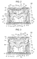
- an imaging apparatus 100 comprises: a substrate PC; an imaging element 2 which is arranged on one surface (an upper surface in the drawing) of the substrate PC; an optical member 1 which condenses a light in an imaging area (a later-described photoelectric conversion portion 2a) of this imaging element 2 and forms a subject image; a mirror frame 3 which covers and hides the optical member 1 and the imaging element 2; a douser 4 which is provided to the mirror frame (an outer frame member) 3 and has the light shielding properties; an IR cut filter 5 which is supported by the douser 4; a first pressing member 6 which is provided above the optical member 1 and presses the optical member 1 downward (rearward along the optical axis Y); a second pressing member 7 which is provided below the optical member 1 and presses the optical member 1 upward (frontward along the optical axis Y); and a positioning electrical component 8 which is attached to the substrate PC and positions the mirror frame 3 with respect to the substrate PC; and others.
- the optical member 1 has a transparent glass or plastic material as its material and, as shown in FIGS. 2 and 3, and comprises a first lens member 9 (a rear optical member) arranged on the substrate PC side (rearward along the optical axis Y), a second lens member 10 (a front optical member) which is provided above this first lens member 9 (frontward along the optical axis Y), and an aperture plate 11 which is provided between the first lens member 9 and the second lens member 10 and adjusts a quantity of a light which enters the first lens member portion 9. It is to be noted that the first lens member 9 and the second lens member 10 have the same optical axis Y.
- the first lens member 9 comprises a lens portion 9a having a convex lens shape and a lower leg portion 9b having a tubular shape around the lens portion 9a, and a contact portion 9c ... which comes into contact with the surface of the imaging element 2 in the regular imaging mode is provided at the lower end portion of the lower leg portion 9b.
- an extending portion 9d extending toward the side to come into contact with the mirror frame 3 is formed at the side portion of the lower leg portion 9b.
- One end of the second pressing member 7 is elastically in contact with the lower surface (the rear surface along the optical axis Y) of this extending portion 9d.
- a protruding portion 3e (which will be described later) which is provided on the inner wall of the mirror frame 3 and protrudes inward in the radial direction of the inner wall is formed above the extending portion 9d (frontward along the optical axis Y) in such a manner that the lower surface of the protruding portion 3e can come into contact with the upper surface of the extending portion 9d.
- the optical member 1 including the first lens member 9 and the second lens member 10 laminated on the first lens member 9 moves to be pushed up by the pressing force of the second pressing member 7, the upward movement is restricted when the extending portion 9d comes into contact with the protruding portion 3e, and the optical member 1 is positioned in the macro imaging mode.
- the lower end of the first pressing member 6 is elastically brought into contact with the upper surface of the lower leg portion 9b of the first lens member 9. Further, in the regular imaging mode, when the first lens member 9 is pressed downward by this first pressing member 6, the first lens member 9 is brought into contact with the imaging element 2, thereby positioning the optical member 1 in the regular imaging mode.
- an engagement portion 9e which engages with the second lens member 10 is provided on the upper surface of the lower leg portion 9b.
- This engagement portion 9e is provided to annularly protrude from the upper surface of the lower leg portion 9b in such a manner that the lens portion 9a is surrounded.
- the aperture plate 11 which is formed of a material having the light shielding properties and has an opening 11a as an aperture which restricts an F number of the lens portion 9a is fixed around the lens portion 9a on the inner side of this engagement portion 9e by an adhesive.
- the second lens member 10 comprises a tubular lower leg portion 10b around the lens portion 10a, and an engagement target portion 10c which is engaged with the engagement portion 9e of the first lens member 9 is provided below this lower leg portion 10b.
- This engagement target portion 10c has a ring shape protruding from the lower surface of the lower leg portion 10b, and an outer peripheral surface thereof is in contact with the inner peripheral surface of the engagement portion 9e of the first lens member 9 while a lower surface of the same is in contact with the aperture plate 11. Additionally, in this state, the lower surface of the lower leg portion 10b is in contact with the upper surface of the lower leg portion 9b of the first lens member 9. Further, the engagement portion 9e of the first lens member 9 and the engagement target portion 10c are bonded to each other. Therefore, the second lens member 10 can move in the vertical direction (the cross direction along the optical axis Y) in cooperation with the first lens member 9.
- the optical axis Y of the first lens member 9 can be prevented from deviating from the counterpart of the second lens member 10.
- the imaging element 2 is an image sensor, and comprises, e.g., a CMOS type image sensor, a CCD type image sensor or the like.
- the lower surface of the imaging element 2 having a rectangular thin plate shape is attached to the upper surface of the substrate PC.
- the photoelectric conversion portion 2a as an imaging area in which pixels are two-dimensionally arranged is formed at the center of the upper surface of the imaging element 2.
- the contact portion 9c of the first lens member 9 comes into contact with a non-imaging area 2b provided outside the photoelectric conversion portion 2a, and a processing portion (not shown) is formed in this area.
- a plurality of pads are arranged in the vicinity of an outer edge of the processing portion.
- Each pad as a wire terminal is connected with the substrate PC through a wire W.
- the wire W is connected with a predetermined circuit on the substrate PC connected with the predetermined circuit on the substrate PC.
- the mirror frame 3 is a case formed of a material having the light shielding properties, arranged outside the optical member 1 and functions as an outer frame member.
- the mirror frame 3 comprises a main body member 3c including a cylindrical upper portion 3a and a prismatic lower portion 3b, and a lid member 3d which is separately provided at an upper end portion (a front end portion in a direction along the optical axis Y) of the upper portion 3a of the main body member 3c.
- the lower end portion of the lower portion 3b of the main body member 3c is secured on the substrate PC by an adhesive B.
- a protruding portion 3e protruding from the inner peripheral surface is provided on the inner peripheral surface of the upper portion 3a of the main body member 3c between the optical member 1 and the lid member 3d, and the extending portion 9d of the first lens member 9 comes into contact with the lower surface of this protruding portion 3e in case of the macro imaging mode.
- a support portion 3f which protrudes from the inner peripheral surface of the lower portion 3b of the main body member 3c and supports the second pressing member 7.
- This support portion 3f is engaged with the leg portion 9c of the first lens member 9, and a position of the optical member 1 is restricted to the mirror frame 3 in such a manner the optical member 1 is prevented from rotating around the optical axis Y of the lens portion 9a of the first optical portion 10.
- the optical member 1 Since the position of the optical member 1 is restricted to the mirror frame 3 in this manner, when the mirror frame 3 is positioned and arranged at a predetermined position of the substrate PC based on, e.g., the later-described positioning electrical component 8, the optical member 1 can be arranged at a predetermined position of the substrate PC, and the center of the photoelectric conversion portion 2a of the imaging element 2 provided to the substrate PC can be matched with the optical axis Y of the lens portion 9a of the first lens member 9 fitted to the mirror frame 3, for example.
- the optical member 1 since the position of the optical member 1 is restricted to the mirror frame 3, the optical member 1 is hard to deviate from a predetermined position in a state where the mirror frame 3 is arranged and fixed at a predetermined position of the substrate PC, and it is easy to maintain a state in which the optical axis Y of the lens portion 9a of the optical member 1 is matched with the center of the photoelectric conversion portion 2a of the imaging element 2, for example.
- the lid member 3d of the mirror frame 3 is screwed to the upper end portion of the upper portion 3a, and can move along the optical axis Y in such a manner that it is raised upward (frontward along the optical axis Y) from the upper portion 3a of the mirror frame 3 by swiveling.
- the lid member 3d has a shape which covers the upper surface of the optical member 1, and is provided with an opening portion 3dd as a first aperture which adjusts a quantity of a light which enters the second lens portion 10.
- the movement of the lid member 3d is carried out by, e.g., a manual operation using, e.g., a non-illustrated lever member or switch member provided to the imaging apparatus 100 or an automatic operation or the like using driving means such as a driving motor, but it is not restricted thereto.
- the lid member 3d may be formed of a shape-memory alloy and configured to be deformed and moved along the optical axis Y when heated to a shape-memory temperature in advance.
- the douser 4 is attached at the upper end of the lid member 3d by an adhesive or the like. Furthermore, the douser 4 has an opening 4a as a second aperture at the center thereof.
- the IR cut filter 5 is formed of a material having infrared absorbing characteristics, and bonded below the opening 4a at the center of the douser 4 by an adhesive or the like.
- this douser 4 and the IR cut filter 5 constitute a cover member 12. Since the substrate PC, the mirror frame 3 and the cover member 12 are pressed against and bonded to each other in this manner, and hence the imaging apparatus 100 has the dust-proof and damp-proof configuration.
- Each of the first pressing member 6 and the second pressing member 7 comprises an elastic member such as a coil spring. Additionally, the first pressing member 6 is elastically interposed between the first lens member 9 an the lid member 3d, and the second pressing member 7 is elastically interposed between the first lens member 9 and the support portion 3f formed below the mirror frame 3.
- the first lens member 9 is pressed downward (rearward along the optical axis Y) in the drawing by a predetermined pressing force, biased and positioned to come into contact with the imaging element 2.
- the state where the first lens member 9 is positioned to come into contact with the imaging element 2 as described above is determined as a state set in the regular imaging mode.
- the second lens member 10 laminated on the first lens member 9 also moves upward in cooperation with the first lens member 9.
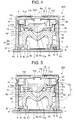
- the state in which the first lens member 9 of the optical member 1 is positioned to come into contact with the protruding portion 3e as described above is determined as a state set in the macro imaging mode.
- a distance between the optical member 1 and a subject becomes short, namely, a focal distance of the optical member 1 becomes shorter than that in case of the regular imaging mode, and hence close-up shooting and approach shooting of a subject are enabled.
- the optical member 1 is pressed downward in FIG. 2 to come into contact with the imaging element 2 since the pressing force of the first pressing member 6 is larger than the pressing force of the second pressing member 7 in the regular imaging mode, but the lower end of the second pressing member 7 is in contact with the upper surface of the support portion 3f of the main body member 3c, and the buffering effect works due to the elasticity of the second pressing member 7, thereby giving no damage to the imaging element 2.
- the positioning electrical component 8 is, e.g., a capacitor, a resistor, a diode and the like, and arranged in proximity to the mirror frame 3 between the imaging element 2 and the mirror frame 3 on the substrate PC in FIG. 2. Additionally, a height from the substrate PC to the upper end portion of the positioning electrical component 8 is larger than a height from the substrate PC to the upper end portion of the imaging element 2. Further, the positioning electrical component 8 serves as a positioning mark for the mirror frame 3 when securing the mirror frame 3 on the substrate PC. Furthermore, since the upper end of the positioning electrical component 8 is higher than the upper end of the imaging element 2, the mirror frame 3 can be prevented from coming into contact with the imaging element 2 to damage the wire W and the like of the imaging element 2.
- the positioning electrical component 8 is not restricted to, e.g., a capacitor, a resistor, a diode and the like, and an electrical component required for the imaging device 100 can be used.
- the lid member 3d which can move along the optical axis Y is attached to the upper surface of the main body member 3c of the mirror frame 3, the protruding portion 3e protruding from the inner peripheral surface of the main body member 3c is provided between the optical member 1 and the lid member 3d, the first pressing member 6 which presses the optical member 1 toward the substrate PC side is elastically interposed between the lid member 3d and the optical member 1, and the second pressing member 7 which presses the optical member 1 toward the lid member 3d side is elastically interposed between the support portion 3e and the optical member 1.
- the pressing force of the first pressing member 6 becomes larger than the pressing force of the second pressing member 7 in a state where the optical member 1 is in contact with the imaging element 2, while the pressing force of the second pressing member 7 becomes larger than the pressing force of the first pressing member 6 and the optical member 1 moves upward (frontward along the optical axis Y) to come into contact with the protruding portion 3e when the lid member 3d moves upward (frontward along the optical axis Y) by a predetermined distance or more.
- the imaging apparatus 100 can perform the imaging processing based on the two focal distances (the imaging modes), i.e., the focal distance (the regular imaging mode) when the optical member 1 is in contact with the imaging element 2 and the macro imaging mode having the focal distance to a subject which is shorter than that of the regular imaging mode.
- the imaging modes i.e., the focal distance (the regular imaging mode) when the optical member 1 is in contact with the imaging element 2 and the macro imaging mode having the focal distance to a subject which is shorter than that of the regular imaging mode.
- the optical member 1 is positioned by contact with the imaging element 2 or contact with the protruding portion 3e by the first pressing member 6 and the second pressing member 7, the accurate optical function can be realized.
- the focal distances can be adjusted and switched by the arrangement of simple members such as the pressing members and the like or the movement of the lid member 3d, thereby diversifying the optical function without requiring the manufacturing cost or trouble.
- the lid member 3d is screwed to the main body member 3c, and the lid member 3d can move along the optical axis Y by rotating the lid member 3d, thus realizing the movement of the lid member 3d without providing a complicated mechanism.
- the optical member 1 configured to comprise the first lens member 9 and the second lens member 10, it may be configured to include one lens member only.
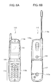
- FIGS. 4 and 5 An imaging apparatus 200 which is a modification of the imaging apparatus 100 according to this embodiment will now be described with reference to FIGS. 4 and 5. It is to be noted that like reference numerals denote parts equal to those of the imaging apparatus 100, and a description will be given as to different parts only.
- FIG. 4 is a partially eliminated cross-sectional view of the imaging apparatus 200 in the regular imaging mode
- FIG. 5 is a partially eliminated cross-sectional view of the imaging apparatus 200 in the macro imaging mode.
- an extending portion 10e extending in the inner peripheral surface direction of the mirror frame 3 is formed to the second lens member 10 of the optical member 1 in the imaging apparatus 200.
- This extending portion 10e comes into contact with the protruding portion 3e in the macro imaging mode, and the second lens member 10 is positioned by this contact.
- a third pressing member (corresponding to the first pressing member described in claim 4) 13 which presses the second lens member 10 toward the first lens member 9 is elastically interposed between the upper surface of the second lens member 10 and the lower surface of the lid member 3d.
- a fourth pressing member (corresponding to the second pressing member described in claim 4) 14 which presses the second optical portion 9 upward is elastically interposed between the lower surface of the extending portion 10e of the second lens member 10 and the upper surface of the first lens member 9.
- a fifth pressing member (the third pressing member described in claim 4) which presses the first lens member 9 downward is elastically interposed between the lower surface of the protruding portion 3e and the upper surface of the first lens member 9.
- the pressing force by this fifth pressing member 15 maintains the contact portion 9c of the first lens member 9 in contact with the non-imaging area 2b of the imaging element 2 in both the regular imaging mode and the macro imaging mode without being affected by the pressing forces of the third pressing member 13 and the fourth pressing member 14.
- the pressing force of the third pressing member 13 is larger than the pressing force of the fourth pressing member 14, and hence the second lens member 10 is in contact with the first lens member 9.
- the focal point can be adjusted and the imaging processing in the two imaging modes (the focal distances) can be carried out by moving one of the two laminated optical members.
- the pressing force for the movement can be reduced as compared with the case in which both the first lens member 9 and the second lens member 10 are moved, and hence a reduction in size of the third pressing member 13, the fourth pressing member 15 and the fifth pressing member 16 and size of the imaging apparatus 200 can be realized.
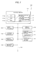
- FIGS. 6 are views showing an exterior configuration of a mobile phone which is an example of a portable terminal apparatus to which the present invention is applied.
- a mobile phone 110 is of a flip type in which a first case 111a and a second case 111b are coupled to each other to be opened and closed by a hinge coupling portion 111c.
- a later-described input section 112 and display section 113 are arranged on a surface which is the inner side when closed.
- a camera button, a function key and others are provided to the input section 112.
- the above-described imaging apparatus 100 is provided so that imaging is possible with the surface which is the outer surface when closed being directed toward a subject.
- an antenna 114a is arranged at the upper portion of the mobile phone 110.
- a power supply control section 117 such as a charging pack is provided on the rear surface side in the second case 111b.
- FIG. 7 is a block diagram showing a functional configuration of the mobile phone 110 depicted in FIG. 6.
- the mobile phone 110 comprises a control section 111, an input section 112, a display section 113, a wireless communication section 114 having an antenna 114a, a storage section 115, an imaging apparatus 100, a power supply control section 117, a receiver section 118 and others, and the respective sections are connected with each other through a bus 119.
- the control section 111 comprises a CPU (Central Processing Unit) 111a, an RAM (Random Access Memory) 111b constituted of a rewritable semiconductor device, an ROM (Read Only Memory) 111c constituted of a non-volatile semiconductor memory and others.
- CPU Central Processing Unit
- RAM Random Access Memory
- ROM Read Only Memory
- the ROM 111c stores therein a basic operation control program for the mobile phone 110, a communication processing program, display data which is displayed in the display section 113 and parameter data concerning imaging (default setting data for automatic imaging and default setting data for preview display processing) as well as an imaging control program c1, a code recognition program c2 and code recognition data c3 which are not illustrated in the drawing.
- the code recognition data c3 is reference data required when setting a code similarity coefficient (Q) which is used to judge whether a two-dimensional code is included as an information code in image data.
- the CPU 111a develops in a work area of the RAM 111b a program specified from various kinds of programs stored in the ROM 111c in accordance with various instructions input from the input section 112 or data input from the wireless communication section 114, and executes various kinds of processing based on the input instructions and the input data in accordance with the program. Further, the CPU 111a stores a processing result in a predetermined area of the RAM 111b and displays the same in the display section 113.
- the CPU 111a reads the imaging control program c1 stored in the ROM 111c and executes later-described imaging control processing.
- the CPU 111a controls the imaging apparatus 100 in accordance with an operation instruction or the like of a user input from the input section 112, stores the captured image data in a predetermined memory or the like of the RAM 111b, and then displays this data in the display section 113 in a preview mode at a frame rate of 25 fps.
- the CPU 111a executes code processing which recognizes a two-dimensional code target which may be possibly a two-dimensional code with respect to the captured image data in accordance with the code recognition program c2. Specifically, the CPU 111a compares the captured image data with the code recognition data c3 every five frames to make a judgment upon whether a two-dimensional code is included in the captured image data. More specifically, the CPU 111a compares the captured image data with the code recognition data c3 as similarity coefficient calculation information to calculate a code similarity coefficient with respect to a two-dimensional code target, and recognizes a two-dimensional code target (an information code target) which may be possibly a two-dimensional code or a two-dimensional code based on a value of this code similarity coefficient.
- the CPU 111a functions as movement controlling means which controls driving means (not shown) for moving the lid member 3d in order to switch the imaging apparatus 100 to execute the imaging processing based on the macro imaging mode from the regular imaging mode.
- the CPU 111a executes decoding processing of the two-dimensional code and also displays this code in the display section 113.
- the CPU 111a executes an operation based on information of the information code subjected to the decoding processing.
- the input section 112 comprises a numeric keypad, various kinds of function switches, a mode changeover switch which switches a talk mode and a camera mode and others, and it is used to, e.g., input an instruction for execution of the imaging processing.
- the display section 113 comprises an LCD (Liquid Crystal Display) panel and the like, and displays information in a screen based on display data input from the control section 11. Furthermore, the display section 113 displays an image captured by the later-described imaging apparatus 100 in the preview mode, a code information content decoded by the control section 111 and others.
- LCD Liquid Crystal Display
- the wireless communication section 114 comprises the antenna 114a which transmits/receives a wireless signal concerning an incoming call or an originating call to/from a wireless base station (not shown), executes a communication protocol for a mobile phone corresponding to a communication scheme complying with, e.g., IMT-2000 (e.g., W-CDMA or cdma2000) with the wireless base station based on an instruction input from the control section 111, and executes transmission/reception of voices or data communication through a communication channel set by this communication scheme.
- IMT-2000 e.g., W-CDMA or cdma2000
- the storage section 115 stores data or the like which is a result of processing executed by the control section 111.
- the storage section 115 stores data of an image captured by the imaging apparatus 100, data of a mail transmitted/received through the wireless communication section 114, data or the like of a call history and others.
- the imaging apparatus 100 has the above-described configuration, and converts an image input through the optical member 1 into an electrical signal by using the imaging element 2 to generate image data. Further, a CCD type image sensor or the like of the imaging element 2 has a function as an optical sensor which detects an ambient light quantity, and outputs a detection signal corresponding to the ambient light quantity to the control section 111.
- the lid member 3d of the imaging apparatus 100 is moved along the optical axis Y by driving means (not shown) driven based on the control by the control section 111. That is, the imaging apparatus 100 is configured in such a manner that the imaging processing based on the regular imaging mode and the macro imaging mode can be switched by the control of the control section 111.
- the power supply control section 117 comprises a secondary battery such as a lithium battery, a nickel battery or a nicad battery, and supplies the power having a predetermined voltage to a drive circuit which drives each section of the mobile phone 110 from a positive terminal and a negative terminal in accordance with the control by the control section 111 when the power supply is turned on.
- a secondary battery such as a lithium battery, a nickel battery or a nicad battery
- the receiver section 118 has a microphone, a speaker, an A/D converting section and a D/A converting section, subjects transmitted voices of a user input from the microphone to A/D conversion processing, outputs the obtained transmitted voice data to the CPU 111a, and subjects received voice data input from the CPU 111a or sound data such as an incoming call sound, an operation confirmation sound or a shutter sound to D/A conversion processing to output the obtained result from the speaker.
- Imaging control processing in the mobile phone 110 will now be described hereinafter with reference to a flowchart of FIG. 8.
- the CPU 111a determines that an imaging processing instruction is input, reads the imaging control program c1 stored in the ROM 111c, develops it in the RAM 111b and starts the control of the imaging processing in accordance with the imaging control program c1.
- the user images a subject by directing the imaging apparatus 100 of the mobile phone 110 toward the subject.
- the imaging apparatus 100 sequentially outputs to the control section 111 the captured image data of the subject which has been condensed by the optical member 1 and image-formed in the photoelectric conversion portion 2a of the imaging element 2 as the imaging processing based on the regular imaging mode (a step S102).
- the CPU 111a advances to a step S106 if it is determined that the number of frames is "5" (the step S105: Yes), while it proceeds to the step S102 if it is determined that the number of frames is not 5 (the step S105: No), and the above-described steps are repeated.
- the CPU 111a reads the code recognition program c2 stored in the ROM 111c, develops the read program in the RAM 111b, and starts the control of the code recognition processing in accordance with this code recognition program c2. Specifically, the CPU 111a compares the captured image data of the subject when the number of frames is "5" with the code recognition data c3 to execute two-dimensional code recognition processing.
- the recognition processing method there are, e.g., a method which recognizes a two-dimensional code by detecting a predetermined cutout symbol indicating that a two-dimensional code exists in captured image data of a subject, a method which recognizes a two-dimensional code based on the concentration of captured image data of a subject, a method which recognizes a predetermined mosaic shape of a two-dimensional code and others, but the present invention is not restricted thereto.
- the CPU 111a compares the captured image data with the code recognition data c3 as the similarity coefficient calculation information to calculate a code similarity coefficient (Q) which is used to judge the possibility of a two-dimensional code of the captured image data.
- the CPU 111a judges whether a value of the calculated code similarity coefficient (Q) is not less than "0.5" (the step S107), and determines that there is the possibility of a predetermined two-dimensional code and advances to the step S108 if it is determined Q is not less than "0.5" (the step S107: Yes).
- the CPU 111a executes the two-dimensional code recognition processing with respect to the captured image data of a subject every five frames. Therefore, the processing load of the CPU 111a is reduced, and the influence on the captured image data acquisition processing of a subject and the captured image data preview display processing which are simultaneously executed can be alleviated.
- the CPU 111a judges whether the code similarity coefficient (Q) is "1" at the step S108, and determines that there is a two-dimensional code and advances to a step S110 when it is determined that Q is "1" (the step S108: Yes).
- the CPU 111a determines that the possibility of a two-dimensional code is indefinite and recognizes that there is a two-dimensional code target (an information code target). Then, the CPU 111a controls the non-illustrated driving means to move the lid member 3d in a direction of a subject so that the imaging apparatus 100 can perform macro shooting, and the macro imaging mode setting processing is thereby executed (a step S111) and the control advances to a step S109.
- the first lens member 9 of the optical member 1 moves upward (frontward along the optical axis Y) with the movement of the lid member 3d of the imaging apparatus 100 along the optical axis Y by the control of the CPU 111a, and the captured image data of a subject in the macro imaging mode is acquired by using the optical member 1 and the imaging element 2 in a state where the first lens member 9 is in contact with the protruding portion 3e, and the acquired data is displayed in the display section 113 in the preview mode.
- the CPU 111a executes the code recognition processing every five frames with respect to the captured image data based on the macro imaging mode simultaneously with the imaging processing and the preview display processing in this macro imaging mode.
- the imaging processing in the macro imaging mode is suitable for the case where a distance to a subject is short as compared with the imaging processing in the regular imaging mode, a two-dimensional code recognition ratio is improved, thereby increasing the possibility that a two-dimensional code target is recognized as a two-dimensional code on the assumption that there is the possibility as a two-dimensional code in the regular imaging mode but not indefinite. Based on this, a ratio of recognizing a two-dimensional code in the captured image data of a subject is improved.
- the CPU 111a executes the decoding processing for the recognized two-dimensional code, and displays a code information content of this two-dimensional code in the display section 113 (a step S112).
- code information content displayed in the display section 113 there are, e.g., character information such as a URL address or an e-mail address, arbitrary image information and others.
- the code information content is, e.g., audio information besides a content which can be displayed in the display section 113, e.g., character information or image information as the code information content
- sound generation processing may be executed from the receiver section 118.
- the CPU 111a judges whether a signal instructing predetermined processing with respect to the code information content displayed in the display section 113 is input by the operation of the input section 112 by a user (a step S113), and executes processing corresponding to the instruction (a step S114) and advances to a step S115 when it is determined that the instruction signal is input (the step S113: Yes).
- the predetermined processing with respect to the code information content is, e.g., an instruction of connection to a URL address when the code information content is the URL address, it is an instruction to create an e-mail to an e-mail address when the code information content is the e-mail address, it is processing of saving in an address book or the like when the code information content is a telephone number, an email-address or the like, and it is processing of saving a displayed image in the display section 113 or the like in any other case, but the present invention is not restricted thereto.
- the CPU 111a advances to a step S115.
- the CPU 111a judges whether an imaging processing end instruction is input by the operation of the input section 112 by a user (the step S115), and the instruction to terminate the imaging processing is output to the imaging apparatus 100 to terminate this imaging control processing if it is determined that the imaging processing end instruction is input (the step S115: Yes).
- the CPU 111a advances to the step S109 and repeats the step S109 and the subsequent steps.
- the processing of recognizing predetermined two-dimensional code data in the captured image data and the two-dimensional code data decoding processing are automatically executed simultaneously with the processing of acquiring the captured image data of a subject by the imaging apparatus 100 and the captured image data preview display processing. Therefore, a user can automatically read and decode a two-dimensional code by performing the same operation as that of the regular imaging processing without performing the troublesome setting in order to recognize and decode a two-dimensional code given to, e.g., a card or a magazine, thereby improving the usability.
- the imaging apparatus 100 is controlled so that the processing is automatically switched to the imaging processing based on the macro imaging mode appropriate to recognition of a two-dimensional code. Therefore, the two-dimensional code recognition accuracy can be increased without imposing the trouble of changing the setting of the imaging mode to a user.
- the imaging mode is not switched, which is efficient.
- the content described in conjunction with this embodiment according to the present invention is a preferred example of the mobile phone 110 according to the present invention, and the present invention is not restricted thereto.
- the method of moving the lid member 3d of the imaging apparatus 100 may be of any type.
- the imaging apparatus in this mobile phone 110 the example in which the imaging apparatus 100 is mounted has been described, but it is possible to adopt a configuration in which the imaging apparatus 200 as a modification of the imaging apparatus 100 is mounted.
- the present invention is not restricted to the two-dimensional code, and it is possible to use any information code, e.g., a bar code or a color code.
- the portable terminal apparatus is not restricted to the mobile phone 110, and it may be a personal computer, a PDA or the like.
- the imaging apparatus according to the present invention can be incorporated in various kinds of products such as a mobile phone, a personal computer, a PDA, an AV device, a television set, a home electric appliance and others.
Landscapes
- Physics & Mathematics (AREA)
- General Physics & Mathematics (AREA)
- Optics & Photonics (AREA)
- Engineering & Computer Science (AREA)
- Signal Processing (AREA)
- Multimedia (AREA)
- Studio Devices (AREA)
- Lens Barrels (AREA)
- Transforming Light Signals Into Electric Signals (AREA)
Abstract
There are provided a highly accurate imaging apparatus
which relatively rarely requires a cost and manufacturing
troubles and can readily adjust a focal point, and a portable
terminal apparatus comprising this imaging apparatus.
According to the imaging apparatus (100) of the present
invention, a lid member (3d) is attached to a mirror frame
(3) in such a manner that the lid member can move along an
optical axis (Y), a first pressing member (6) which presses
an optical member toward a substrate side is elastically
interposed between the lid member (3d) and the optical member
(1), a second pressing member (7) which presses the optical
member (1) toward the lid member (3d) is elastically
interposed between the mirror frame (3) and the optical
member (1), a pressing force of the first pressing member (6)
is larger than a pressing force of the second pressing member
(7) in a state where the optical member (1) is in contact
with the upper surface of the imaging element (2), and the
pressing force of the second pressing member (7) becomes
larger than the pressing force of the first pressing member
(6) and the optical member (1) is moved frontward along the
optical axis (Y) to come into contact with a protruding
portion (3e) protruding from an inner peripheral surface of
the mirror frame (3) when the lid member (3d) moves frontward
along the optical axis (1) over a predetermined distance.
Description
The present invention relates to an imaging apparatus
which can be mounted in a mobile phone or a personal computer,
and a portable terminal apparatus comprising the imaging
apparatus.
In recent years, many portable information terminal
apparatus (which will be referred to as a portable terminal
apparatus hereinafter) having an imaging function such as a
mobile phone in which a small high-performance imaging
apparatus is mounted have been developed.
As such conventional portable terminal apparatuses,
there is one which can perform regular imaging as well as
close-up photography or close-up shooting (which will be
referred to as macro shooting hereinafter) which images a
character or the like in a magazine or a card (see, e.g.,
Japanese Patent Application Laid-open No. 2002-262164).
In the portable terminal apparatus disclosed in this
publication, an imaging apparatus is attached to a terminal
apparatus main body (an electronic device main body) so as to
be capable of swiveling. In detail, this portable terminal
apparatus comprises a plate fixedly provided to the terminal
apparatus main body, a cam groove provided to this plate, and
a protruding portion which engages with the cam groove in a
frame body of a lens which integrally swivels with an imaging
apparatus, and a distance between lenses is adjusted when a
plurality of lenses swivels while being restricted by the cam
groove with the swiveling motion of the imaging device,
thereby enabling adjustment to obtain a magnifying power
suitable for the macro shooting.
In the portable terminal apparatus disclosed in the
above publication, however, since the cam groove must be
provided to the plate or the protruding portion must be
provided to the frame body of the lens, the mechanism is
complicated, thus requiring an increase in cost or
manufacturing troubles. Further, since a focal point is
adjusted by the complicated mechanism, the cam manufacturing
accuracy is required, and the lens attachment
accuracy/assembling accuracy must be high. Furthermore, when
performing the adjustment to obtain a plurality of magnifying
powers, since a plurality of components must be moved, any
component becomes loose by the repeated use, which may
possibly result in an out-of-focus problem.
Moreover, in the portable terminal apparatus disclosed
in the above publication, since the main body must be again
held in accordance with a direction of a subject in order to
swivel the imaging apparatus when switching a focal distance
to perform the shooting, there is a problem of the
inconvenience for a user.
Thus, in order to eliminate the above-described
inconvenience in the prior art, it is an object of the
present invention to provide a highly accurate imaging
apparatus which does not relatively require a high cost and
manufacturing troubles and can easily adjust a focal point,
and a portable terminal apparatus comprising this imaging
apparatus.
To achieve this aim, according to a first aspect of
the present invention, there is provided an imaging apparatus
having: a substrate having an imaging element provided on an
upper surface thereof; an optical member which is separably
in contact with the substrate or the upper surface of the
imaging element and condenses an incident light on the
imaging element; and an outer frame member which covers the
imaging element and the optical member and comprises a main
body member fixedly provided on the substrate, a lid member
attached on an end side of the main body member in such a
manner that the lid member can move along an optical axis of
the optical member, and a protruding portion which is fixedly
provided at a predetermined position between the optical
member and the lid member to protrude inwardly in a radial
direction from an inner peripheral surface of the main body
member, the imaging apparatus comprising:
According to the first aspect, the lid member is
attached at an end of the outer frame member in such a manner
that the lid member can move along an optical axis, the
protruding portion which protrudes inward in the radial
direction from the inner peripheral surface of the main body
member is provided between the optical member and the lid
member, the first pressing member which presses the optical
member toward the substrate side is elastically interposed
between the lid member and the optical member, and the second
pressing member which presses the optical member toward the
lid member side is elastically interposed between the support
member formed below the main body member and the optical
member. Additionally, the pressing force of the first
pressing member is larger than the pressing force of the
second pressing member in a state where the optical member is
in contact with the substrate or the imaging element, and the
pressing force of the second pressing member becomes larger
than the pressing force of the first pressing member and the
optical member moves frontward along the optical axis to come
into contact with the protruding portion when the lid member
moves frontward along the optical axis over a predetermined
distance. Therefore, the imaging apparatus can perform
imaging processing based on two focal distances, i.e., a
focal distance when the optical member is in contact with the
substrate or the imaging element and a focal distance when
the optical member is in contact with the protruding portion.
Further, when the both focal distances are formed, the
optical member is positioned by contact with the substrate or
the imaging element or contact with the protruding portion by
the first pressing member and the second pressing member,
thereby realizing the accurate optical function. Furthermore,
since the focal distances can be adjusted or switched by the
arrangement of simple members such as the pressing members or
movement of the lid member, the optical function can be
diversified without requiring a high manufacturing cost or
trouble.
According to a second aspect of the present invention,
there is provided the imaging apparatus characterized in that
the lid member described in the first aspect is screwed to
the main body member, and the lid member moves along the
optical axis by rotating the lid member.
According to the second aspect, the same advantages as
those of the imaging apparatus described in the first aspect
can be of course obtained and, since the lid member is
screwed to the main body member and can move along the
optical axis by rotating the lid member, the movement of the
lid member can be realized without including a complicated
mechanism, thereby diversifying the optical function without
requiring a high cost and trouble of the imaging apparatus.
According to a third aspect of the present invention,
there is provided the imaging apparatus characterized in that
the optical member described in the first or second aspect
comprises an extending portion which extends to the side and
supports the second pressing member on a rear surface thereof,
and the main body member comprises a support portion which
protrudes from the inner peripheral surface and supports the
second pressing member on a front surface thereof.
According to the third aspect, the same advantages as
those of the imaging apparatus described in the first and
second aspects can be of course obtained and, in particular,
since the second pressing member is supported between the
rear surface of the extending portion which extends to the
side of the optical member and the front surface of the
support portion which protrudes from the inner peripheral
surface of the main body member, the second pressing member
does not come into contact with the substrate or the imaging
element even when the pressing force is applied in such a
manner that the optical member is brought into contact with
the substrate or the imaging element by the first pressing
member, thereby protecting the substrate or the imaging
element.
To achieve the above-described aim, according to a
fourth aspect of the present invention, there is provided an
imaging apparatus having: a substrate having an imaging
element provided on an upper surface thereof; an optical
member which is separably in contact with the substrate or
the upper surface of the imaging element, comprises a front
optical member and a rear optical member which are laminated
in a cross direction so that they have the same optical axis,
and condenses an incident light on the imaging element; and
an outer frame member which covers the imaging element and
the optical member, and comprises a main body member fixedly
provided on the substrate, a lid member attached on an end
side of the main body member in such a manner that the lid
member can move along an optical axis of the optical member,
and a protruding portion which is fixedly provided at a
predetermined position between the optical member and the lid
member to protrude inwardly in a radial direction from an
inner peripheral surface of the main body member, the imaging
apparatus comprising:
According to the fourth aspect, the optical member
comprises the front optical member and the rear optical
member laminated in the vertical direction to have the equal
optical axis, the lid member movable along the optical axis
is attached at the front end of the main body member of the
outer frame member, the protruding portion which protrudes
from the inner peripheral surface of the main body member is
provided between the front optical member and the lid member,
the first pressing member which presses the optical member
toward the rear optical member side is elastically interposed
between the lid member and the front optical member, the
second pressing member which presses the front optical member
toward the lid member side is elastically interposed between
the front optical member and the rear optical member, and the
third pressing member which presses the rear optical member
toward the substrate side is provided. Further, the pressing
force of the first pressing member becomes larger than the
pressing force of the second pressing member in a state where
the front optical member is in contact with the rear optical
member, and the pressing force of the second pressing member
becomes larger than the pressing force of the first pressing
member and the front optical member moves frontward along the
optical axis to come into contact with the protruding portion
when the lid member moves frontward along the optical axis
over a predetermined distance. Therefore, the imaging
apparatus can perform two types of focal point adjustment,
i.e., imaging based on a focal distance when the front
optical member is in contact with the rear optical member and
imaging based on a focal distance when the front optical
member is in contact with the protruding portion. Further,
since the front optical member comes into contact with the
rear optical member or the protruding portion and is thus
positioned by the first and second pressing members when the
both focal distances are formed, the accurate optical
function can be realized. Furthermore, since the focal point
adjustment based on the movement of the front optical member
is realized by the movement of the lid member and the
arrangement of the pressing members, the optical function can
be diversified without requiring a cost and troubles in
manufacture of the imaging apparatus.
Moreover, since the optical member is divided into the
front optical member and the rear optical member and the
front optical member alone is moved to perform the focal
point adjustment, the moving optical member can be further
reduced in size, and the pressing members and others can be
miniaturized, thereby further reducing the size.
According to a fifth aspect of the present invention,
there is provided the imaging apparatus characterized in that
the lid member described in one of the first to fourth
aspects is formed of a shape-memory alloy, and configured to
be deformed and moved along the optical axis when heated.
According to the fifth aspect, the same advantages as
those of the imaging apparatus described in one of the first
to fourth aspects can be of course obtained and, in
particular, since the lid member is formed of a shape-memory
alloy and configured to be deformed by heating to move along
the optical axis, the lid member can be moved when heated by,
e.g., energization, thereby easily and automatically
facilitating the movement of the lid member.
According to a sixth aspect of the present invention,
there is provided a portable terminal apparatus comprising
the imaging apparatus described in one of the first to fifth
aspects.
According to the sixth aspect, the portable terminal
apparatus comprising the imaging apparatus described in one
of the first to fifth aspects can realize diversification of
an imaging function based on the imaging apparatus.
According to a seventh aspect of the present invention,
there is provided the portable terminal apparatus described
in the sixth aspect characterized by comprising movement
controlling means for performing the control to move the lid
member of the imaging apparatus along the optical axis.
According to the seventh aspect, the same advantages
as those of the portable terminal device described in the
sixth aspect can be of course obtained and, in particular,
since the movement controlling means for controlling the
movement of the lid member of the imaging apparatus along the
optical axis is provided, switching of focal distances of the
imaging apparatus can be automatically performed, thereby
improving the usability of a user.
A preferred embodiment according to the present
invention will now be described in detail hereinafter with
reference to the accompanying drawings.
It is to be noted that the following description will
be given on the assumption that a cross direction along an
optical axis Y in an imaging apparatus according to the
present invention is a vertical direction in the diagrammatic
representation in FIGS. 1 to 3.
Here, a macro imaging mode is determined as a mode
which is used to perform imaging apparatus suitable for
approach shooting or close-up shooting in which a shooting
distance (a distance between a lens and a subject) is shorter
than that in a regular imaging mode.
As shown in FIGS. 1 to 3, an imaging apparatus 100
comprises: a substrate PC; an imaging element 2 which is
arranged on one surface (an upper surface in the drawing) of
the substrate PC; an optical member 1 which condenses a light
in an imaging area (a later-described photoelectric
conversion portion 2a) of this imaging element 2 and forms a
subject image; a mirror frame 3 which covers and hides the
optical member 1 and the imaging element 2; a douser 4 which
is provided to the mirror frame (an outer frame member) 3 and
has the light shielding properties; an IR cut filter 5 which
is supported by the douser 4; a first pressing member 6 which
is provided above the optical member 1 and presses the
optical member 1 downward (rearward along the optical axis
Y); a second pressing member 7 which is provided below the
optical member 1 and presses the optical member 1 upward
(frontward along the optical axis Y); and a positioning
electrical component 8 which is attached to the substrate PC
and positions the mirror frame 3 with respect to the
substrate PC; and others.
The optical member 1 has a transparent glass or
plastic material as its material and, as shown in FIGS. 2 and
3, and comprises a first lens member 9 (a rear optical
member) arranged on the substrate PC side (rearward along the
optical axis Y), a second lens member 10 (a front optical
member) which is provided above this first lens member 9
(frontward along the optical axis Y), and an aperture plate
11 which is provided between the first lens member 9 and the
second lens member 10 and adjusts a quantity of a light which
enters the first lens member portion 9. It is to be noted
that the first lens member 9 and the second lens member 10
have the same optical axis Y.
The first lens member 9 comprises a lens portion 9a
having a convex lens shape and a lower leg portion 9b having
a tubular shape around the lens portion 9a, and a contact
portion 9c ... which comes into contact with the surface of the
imaging element 2 in the regular imaging mode is provided at
the lower end portion of the lower leg portion 9b.
Further, an extending portion 9d extending toward the
side to come into contact with the mirror frame 3 is formed
at the side portion of the lower leg portion 9b. One end of
the second pressing member 7 is elastically in contact with
the lower surface (the rear surface along the optical axis Y)
of this extending portion 9d. Furthermore, a protruding
portion 3e (which will be described later) which is provided
on the inner wall of the mirror frame 3 and protrudes inward
in the radial direction of the inner wall is formed above the
extending portion 9d (frontward along the optical axis Y) in
such a manner that the lower surface of the protruding
portion 3e can come into contact with the upper surface of
the extending portion 9d.
Moreover, in case of the macro imaging mode, although
the optical member 1 including the first lens member 9 and
the second lens member 10 laminated on the first lens member
9 moves to be pushed up by the pressing force of the second
pressing member 7, the upward movement is restricted when the
extending portion 9d comes into contact with the protruding
portion 3e, and the optical member 1 is positioned in the
macro imaging mode.
Additionally, the lower end of the first pressing
member 6 is elastically brought into contact with the upper
surface of the lower leg portion 9b of the first lens member
9. Further, in the regular imaging mode, when the first lens
member 9 is pressed downward by this first pressing member 6,
the first lens member 9 is brought into contact with the
imaging element 2, thereby positioning the optical member 1
in the regular imaging mode.
Furthermore, an engagement portion 9e which engages
with the second lens member 10 is provided on the upper
surface of the lower leg portion 9b. This engagement portion
9e is provided to annularly protrude from the upper surface
of the lower leg portion 9b in such a manner that the lens
portion 9a is surrounded.
Moreover, the aperture plate 11 which is formed of a
material having the light shielding properties and has an
opening 11a as an aperture which restricts an F number of the
lens portion 9a is fixed around the lens portion 9a on the
inner side of this engagement portion 9e by an adhesive.
The second lens member 10 comprises a tubular lower
leg portion 10b around the lens portion 10a, and an
engagement target portion 10c which is engaged with the
engagement portion 9e of the first lens member 9 is provided
below this lower leg portion 10b. This engagement target
portion 10c has a ring shape protruding from the lower
surface of the lower leg portion 10b, and an outer peripheral
surface thereof is in contact with the inner peripheral
surface of the engagement portion 9e of the first lens member
9 while a lower surface of the same is in contact with the
aperture plate 11. Additionally, in this state, the lower
surface of the lower leg portion 10b is in contact with the
upper surface of the lower leg portion 9b of the first lens
member 9. Further, the engagement portion 9e of the first
lens member 9 and the engagement target portion 10c are
bonded to each other. Therefore, the second lens member 10
can move in the vertical direction (the cross direction along
the optical axis Y) in cooperation with the first lens member
9.
Furthermore, when the engagement portion 9e of the
first lens member 9 is engaged with the engagement target
portion 10c of the second lens member 10, the optical axis Y
of the first lens member 9 can be prevented from deviating
from the counterpart of the second lens member 10.
The imaging element 2 is an image sensor, and
comprises, e.g., a CMOS type image sensor, a CCD type image
sensor or the like. The lower surface of the imaging element
2 having a rectangular thin plate shape is attached to the
upper surface of the substrate PC. The photoelectric
conversion portion 2a as an imaging area in which pixels are
two-dimensionally arranged is formed at the center of the
upper surface of the imaging element 2. The contact portion
9c of the first lens member 9 comes into contact with a non-imaging
area 2b provided outside the photoelectric conversion
portion 2a, and a processing portion (not shown) is formed in
this area.
Moreover, a plurality of pads (not shown) are arranged
in the vicinity of an outer edge of the processing portion.
Each pad as a wire terminal is connected with the substrate
PC through a wire W. The wire W is connected with a
predetermined circuit on the substrate PC connected with the
predetermined circuit on the substrate PC.
The mirror frame 3 is a case formed of a material
having the light shielding properties, arranged outside the
optical member 1 and functions as an outer frame member.
As shown in FIGS. 1 to 3, the mirror frame 3 comprises
a main body member 3c including a cylindrical upper portion
3a and a prismatic lower portion 3b, and a lid member 3d
which is separately provided at an upper end portion (a front
end portion in a direction along the optical axis Y) of the
upper portion 3a of the main body member 3c.
Additionally, the lower end portion of the lower
portion 3b of the main body member 3c is secured on the
substrate PC by an adhesive B.
Further, a protruding portion 3e protruding from the
inner peripheral surface is provided on the inner peripheral
surface of the upper portion 3a of the main body member 3c
between the optical member 1 and the lid member 3d, and the
extending portion 9d of the first lens member 9 comes into
contact with the lower surface of this protruding portion 3e
in case of the macro imaging mode.
Furthermore, there is provided a support portion 3f
which protrudes from the inner peripheral surface of the
lower portion 3b of the main body member 3c and supports the
second pressing member 7. This support portion 3f is engaged
with the leg portion 9c of the first lens member 9, and a
position of the optical member 1 is restricted to the mirror
frame 3 in such a manner the optical member 1 is prevented
from rotating around the optical axis Y of the lens portion
9a of the first optical portion 10.
Since the position of the optical member 1 is
restricted to the mirror frame 3 in this manner, when the
mirror frame 3 is positioned and arranged at a predetermined
position of the substrate PC based on, e.g., the later-described
positioning electrical component 8, the optical
member 1 can be arranged at a predetermined position of the
substrate PC, and the center of the photoelectric conversion
portion 2a of the imaging element 2 provided to the substrate
PC can be matched with the optical axis Y of the lens portion
9a of the first lens member 9 fitted to the mirror frame 3,
for example.
Moreover, since the position of the optical member 1
is restricted to the mirror frame 3, the optical member 1 is
hard to deviate from a predetermined position in a state
where the mirror frame 3 is arranged and fixed at a
predetermined position of the substrate PC, and it is easy to
maintain a state in which the optical axis Y of the lens
portion 9a of the optical member 1 is matched with the center
of the photoelectric conversion portion 2a of the imaging
element 2, for example.
The lid member 3d of the mirror frame 3 is screwed to
the upper end portion of the upper portion 3a, and can move
along the optical axis Y in such a manner that it is raised
upward (frontward along the optical axis Y) from the upper
portion 3a of the mirror frame 3 by swiveling.
Additionally, the lid member 3d has a shape which
covers the upper surface of the optical member 1, and is
provided with an opening portion 3dd as a first aperture
which adjusts a quantity of a light which enters the second
lens portion 10.
It is to be noted that the movement of the lid member
3d is carried out by, e.g., a manual operation using, e.g., a
non-illustrated lever member or switch member provided to the
imaging apparatus 100 or an automatic operation or the like
using driving means such as a driving motor, but it is not
restricted thereto.
Further, the lid member 3d may be formed of a shape-memory
alloy and configured to be deformed and moved along
the optical axis Y when heated to a shape-memory temperature
in advance.
The douser 4 is attached at the upper end of the lid
member 3d by an adhesive or the like. Furthermore, the
douser 4 has an opening 4a as a second aperture at the center
thereof.
The IR cut filter 5 is formed of a material having
infrared absorbing characteristics, and bonded below the
opening 4a at the center of the douser 4 by an adhesive or
the like.
Moreover, this douser 4 and the IR cut filter 5
constitute a cover member 12. Since the substrate PC, the
mirror frame 3 and the cover member 12 are pressed against
and bonded to each other in this manner, and hence the
imaging apparatus 100 has the dust-proof and damp-proof
configuration.
Each of the first pressing member 6 and the second
pressing member 7 comprises an elastic member such as a coil
spring. Additionally, the first pressing member 6 is
elastically interposed between the first lens member 9 an the
lid member 3d, and the second pressing member 7 is
elastically interposed between the first lens member 9 and
the support portion 3f formed below the mirror frame 3.
Further, as shown in FIG. 2, in a state where the lid
member 3d is not raised from the upper surface of the main
body member 3c, the elasticity of the first pressing member 6
is stronger than that of the second pressing member 7.
Therefore, the first lens member 9 is pressed downward
(rearward along the optical axis Y) in the drawing by a
predetermined pressing force, biased and positioned to come
into contact with the imaging element 2.
Furthermore, the state where the first lens member 9
is positioned to come into contact with the imaging element 2
as described above is determined as a state set in the
regular imaging mode.
On the other hand, as shown in FIG. 3, when the lid
member 3d is raised upward (frontward along the optical axis
Y) by swiveling, the elasticity of the first pressing member
is weakened, and the elasticity of the second pressing member
7 becomes stronger than the elasticity of the first pressing
member 6. Then, the first lens member 9 moves upward
(frontward along the optical axis Y) by the pressing force of
the second pressing member 7, and the contact portion 9c is
separated from the upper surface of the imaging element 2.
Then, when the extending portion 9d of the first lens member
9 is brought into contact with the lower surface of the
protruding portion 3e of the mirror frame 3, the further
movement (a separation distance) is restricted.
It is to be noted that the second lens member 10
laminated on the first lens member 9 also moves upward in
cooperation with the first lens member 9.
Furthermore, the state in which the first lens member
9 of the optical member 1 is positioned to come into contact
with the protruding portion 3e as described above is
determined as a state set in the macro imaging mode.
Moreover, in case of the macro imaging mode, a
distance between the optical member 1 and a subject becomes
short, namely, a focal distance of the optical member 1
becomes shorter than that in case of the regular imaging mode,
and hence close-up shooting and approach shooting of a
subject are enabled.
It is to be noted that the optical member 1 is pressed
downward in FIG. 2 to come into contact with the imaging
element 2 since the pressing force of the first pressing
member 6 is larger than the pressing force of the second
pressing member 7 in the regular imaging mode, but the lower
end of the second pressing member 7 is in contact with the
upper surface of the support portion 3f of the main body
member 3c, and the buffering effect works due to the
elasticity of the second pressing member 7, thereby giving no
damage to the imaging element 2.
The positioning electrical component 8 is, e.g., a
capacitor, a resistor, a diode and the like, and arranged in
proximity to the mirror frame 3 between the imaging element 2
and the mirror frame 3 on the substrate PC in FIG. 2.
Additionally, a height from the substrate PC to the upper end
portion of the positioning electrical component 8 is larger
than a height from the substrate PC to the upper end portion
of the imaging element 2. Further, the positioning
electrical component 8 serves as a positioning mark for the
mirror frame 3 when securing the mirror frame 3 on the
substrate PC. Furthermore, since the upper end of the
positioning electrical component 8 is higher than the upper
end of the imaging element 2, the mirror frame 3 can be
prevented from coming into contact with the imaging element 2
to damage the wire W and the like of the imaging element 2.
It is to be noted that the positioning electrical
component 8 is not restricted to, e.g., a capacitor, a
resistor, a diode and the like, and an electrical component
required for the imaging device 100 can be used.
As described above, in the imaging apparatus 100
according to this embodiment of the present invention, the
lid member 3d which can move along the optical axis Y is
attached to the upper surface of the main body member 3c of
the mirror frame 3, the protruding portion 3e protruding from
the inner peripheral surface of the main body member 3c is
provided between the optical member 1 and the lid member 3d,
the first pressing member 6 which presses the optical member
1 toward the substrate PC side is elastically interposed
between the lid member 3d and the optical member 1, and the
second pressing member 7 which presses the optical member 1
toward the lid member 3d side is elastically interposed
between the support portion 3e and the optical member 1.
Further, the pressing force of the first pressing
member 6 becomes larger than the pressing force of the second
pressing member 7 in a state where the optical member 1 is in
contact with the imaging element 2, while the pressing force
of the second pressing member 7 becomes larger than the
pressing force of the first pressing member 6 and the optical
member 1 moves upward (frontward along the optical axis Y) to
come into contact with the protruding portion 3e when the lid
member 3d moves upward (frontward along the optical axis Y)
by a predetermined distance or more. Therefore, the imaging
apparatus 100 can perform the imaging processing based on the
two focal distances (the imaging modes), i.e., the focal
distance (the regular imaging mode) when the optical member 1
is in contact with the imaging element 2 and the macro
imaging mode having the focal distance to a subject which is
shorter than that of the regular imaging mode.
Furthermore, in the both imaging modes, since the
optical member 1 is positioned by contact with the imaging
element 2 or contact with the protruding portion 3e by the
first pressing member 6 and the second pressing member 7, the
accurate optical function can be realized.
Moreover, the focal distances can be adjusted and
switched by the arrangement of simple members such as the
pressing members and the like or the movement of the lid
member 3d, thereby diversifying the optical function without
requiring the manufacturing cost or trouble.
Additionally, the lid member 3d is screwed to the main
body member 3c, and the lid member 3d can move along the
optical axis Y by rotating the lid member 3d, thus realizing
the movement of the lid member 3d without providing a
complicated mechanism.
It is to be noted that the shape, the configuration
and others of each member in the imaging apparatus 100
according to this embodiment of the present invention are not
restricted to those descried above.
For example, although the description has been given
as to the optical member 1 configured to comprise the first
lens member 9 and the second lens member 10, it may be
configured to include one lens member only.
An imaging apparatus 200 which is a modification of
the imaging apparatus 100 according to this embodiment will
now be described with reference to FIGS. 4 and 5. It is to
be noted that like reference numerals denote parts equal to
those of the imaging apparatus 100, and a description will be
given as to different parts only.
It is to be noted that FIG. 4 is a partially
eliminated cross-sectional view of the imaging apparatus 200
in the regular imaging mode and FIG. 5 is a partially
eliminated cross-sectional view of the imaging apparatus 200
in the macro imaging mode.
As shown in FIGS. 4 and 5, an extending portion 10e
extending in the inner peripheral surface direction of the
mirror frame 3 is formed to the second lens member 10 of the
optical member 1 in the imaging apparatus 200. This
extending portion 10e comes into contact with the protruding
portion 3e in the macro imaging mode, and the second lens
member 10 is positioned by this contact.
A third pressing member (corresponding to the first
pressing member described in claim 4) 13 which presses the
second lens member 10 toward the first lens member 9 is
elastically interposed between the upper surface of the
second lens member 10 and the lower surface of the lid member
3d.
Additionally, a fourth pressing member (corresponding
to the second pressing member described in claim 4) 14 which
presses the second optical portion 9 upward is elastically
interposed between the lower surface of the extending portion
10e of the second lens member 10 and the upper surface of the
first lens member 9.
Further, a fifth pressing member (the third pressing
member described in claim 4) which presses the first lens
member 9 downward is elastically interposed between the lower
surface of the protruding portion 3e and the upper surface of
the first lens member 9. The pressing force by this fifth
pressing member 15 maintains the contact portion 9c of the
first lens member 9 in contact with the non-imaging area 2b
of the imaging element 2 in both the regular imaging mode and
the macro imaging mode without being affected by the pressing
forces of the third pressing member 13 and the fourth
pressing member 14.
Furthermore, as shown in FIG. 4, in a state where the
lid member 3d is not moved, as the regular imaging mode, the
pressing force of the third pressing member 13 is larger than
the pressing force of the fourth pressing member 14, and
hence the second lens member 10 is in contact with the first
lens member 9.
Moreover, as shown in FIG. 5, when the lid member 3d
is moved upward over a predetermined distance, the pressing
force of the fourth pressing member 14 becomes larger than
the pressing force of the third pressing member 13, the
second lens member 10 is separated from the first lens member
9 and moved upward by the pressing force of the fourth
pressing member 14, and the extending portion 10e comes into
contact with the protruding portion 3e. As a result, the
further movement (the separation movement) is restricted,
and positioning in the macro imaging mode is performed. In
this macro imaging mode, since the second lens member 10
moves toward a subject, and a focal distance to the subject
becomes shorter than that in the regular imaging mode,
thereby enabling close-up shooting or approach shooting of
the subject.
As described above, according to the imaging apparatus
200, the focal point can be adjusted and the imaging
processing in the two imaging modes (the focal distances) can
be carried out by moving one of the two laminated optical
members.
Additionally, since the focal point is adjusted by
moving the second lens member 10 only, the pressing force for
the movement can be reduced as compared with the case in
which both the first lens member 9 and the second lens member
10 are moved, and hence a reduction in size of the third
pressing member 13, the fourth pressing member 15 and the
fifth pressing member 16 and size of the imaging apparatus
200 can be realized.
FIGS. 6 are views showing an exterior configuration of
a mobile phone which is an example of a portable terminal
apparatus to which the present invention is applied. As
shown in FIGS. 6, a mobile phone 110 is of a flip type in
which a first case 111a and a second case 111b are coupled to
each other to be opened and closed by a hinge coupling
portion 111c.
As shown in FIG. 6A, a later-described input section
112 and display section 113 are arranged on a surface which
is the inner side when closed. A camera button, a function
key and others are provided to the input section 112.
Further, as shown in FIG. 6B, the above-described imaging
apparatus 100 is provided so that imaging is possible with
the surface which is the outer surface when closed being
directed toward a subject. As shown in FIGS. 6A and 6B, an
antenna 114a is arranged at the upper portion of the mobile
phone 110. Furthermore, a power supply control section 117
such as a charging pack is provided on the rear surface side
in the second case 111b.
FIG. 7 is a block diagram showing a functional
configuration of the mobile phone 110 depicted in FIG. 6. As
shown in FIG. 7, the mobile phone 110 comprises a control
section 111, an input section 112, a display section 113, a
wireless communication section 114 having an antenna 114a, a
storage section 115, an imaging apparatus 100, a power supply
control section 117, a receiver section 118 and others, and
the respective sections are connected with each other through
a bus 119.
The control section 111 comprises a CPU (Central
Processing Unit) 111a, an RAM (Random Access Memory) 111b
constituted of a rewritable semiconductor device, an ROM
(Read Only Memory) 111c constituted of a non-volatile
semiconductor memory and others.
The ROM 111c stores therein a basic operation control
program for the mobile phone 110, a communication processing
program, display data which is displayed in the display
section 113 and parameter data concerning imaging (default
setting data for automatic imaging and default setting data
for preview display processing) as well as an imaging control
program c1, a code recognition program c2 and code
recognition data c3 which are not illustrated in the drawing.
In this example, the code recognition data c3 is reference
data required when setting a code similarity coefficient (Q)
which is used to judge whether a two-dimensional code is
included as an information code in image data.
The CPU 111a develops in a work area of the RAM 111b a
program specified from various kinds of programs stored in
the ROM 111c in accordance with various instructions input
from the input section 112 or data input from the wireless
communication section 114, and executes various kinds of
processing based on the input instructions and the input data
in accordance with the program. Further, the CPU 111a stores
a processing result in a predetermined area of the RAM 111b
and displays the same in the display section 113.
Specifically, the CPU 111a reads the imaging control
program c1 stored in the ROM 111c and executes later-described
imaging control processing.
As the imaging control processing, the CPU 111a
controls the imaging apparatus 100 in accordance with an
operation instruction or the like of a user input from the
input section 112, stores the captured image data in a
predetermined memory or the like of the RAM 111b, and then
displays this data in the display section 113 in a preview
mode at a frame rate of 25 fps.
Furthermore, the CPU 111a executes code processing
which recognizes a two-dimensional code target which may be
possibly a two-dimensional code with respect to the captured
image data in accordance with the code recognition program c2.
Specifically, the CPU 111a compares the captured image data
with the code recognition data c3 every five frames to make a
judgment upon whether a two-dimensional code is included in
the captured image data. More specifically, the CPU 111a
compares the captured image data with the code recognition
data c3 as similarity coefficient calculation information to
calculate a code similarity coefficient with respect to a
two-dimensional code target, and recognizes a two-dimensional
code target (an information code target) which may be
possibly a two-dimensional code or a two-dimensional code
based on a value of this code similarity coefficient.
Moreover, when the code similarity coefficient may
possibly include a code but there is a two-dimensional code
target determined as an inconclusive value, the CPU 111a
functions as movement controlling means which controls
driving means (not shown) for moving the lid member 3d in
order to switch the imaging apparatus 100 to execute the
imaging processing based on the macro imaging mode from the
regular imaging mode.
Additionally, when a two-dimensional code is
recognized in the imaging data, the CPU 111a executes
decoding processing of the two-dimensional code and also
displays this code in the display section 113.
Further, the CPU 111a executes an operation based on
information of the information code subjected to the decoding
processing.
The input section 112 comprises a numeric keypad,
various kinds of function switches, a mode changeover switch
which switches a talk mode and a camera mode and others, and
it is used to, e.g., input an instruction for execution of
the imaging processing.
The display section 113 comprises an LCD (Liquid
Crystal Display) panel and the like, and displays information
in a screen based on display data input from the control
section 11. Furthermore, the display section 113 displays an
image captured by the later-described imaging apparatus 100
in the preview mode, a code information content decoded by
the control section 111 and others.
The wireless communication section 114 comprises the
antenna 114a which transmits/receives a wireless signal
concerning an incoming call or an originating call to/from a
wireless base station (not shown), executes a communication
protocol for a mobile phone corresponding to a communication
scheme complying with, e.g., IMT-2000 (e.g., W-CDMA or
cdma2000) with the wireless base station based on an
instruction input from the control section 111, and executes
transmission/reception of voices or data communication
through a communication channel set by this communication
scheme.
The storage section 115 stores data or the like which
is a result of processing executed by the control section 111.
For example, the storage section 115 stores data of an image
captured by the imaging apparatus 100, data of a mail
transmitted/received through the wireless communication
section 114, data or the like of a call history and others.
The imaging apparatus 100 has the above-described
configuration, and converts an image input through the
optical member 1 into an electrical signal by using the
imaging element 2 to generate image data. Further, a CCD
type image sensor or the like of the imaging element 2 has a
function as an optical sensor which detects an ambient light
quantity, and outputs a detection signal corresponding to the
ambient light quantity to the control section 111.
Furthermore, the lid member 3d of the imaging
apparatus 100 is moved along the optical axis Y by driving
means (not shown) driven based on the control by the control
section 111. That is, the imaging apparatus 100 is
configured in such a manner that the imaging processing based
on the regular imaging mode and the macro imaging mode can be
switched by the control of the control section 111.
The power supply control section 117 comprises a
secondary battery such as a lithium battery, a nickel battery
or a nicad battery, and supplies the power having a
predetermined voltage to a drive circuit which drives each
section of the mobile phone 110 from a positive terminal and
a negative terminal in accordance with the control by the
control section 111 when the power supply is turned on.
The receiver section 118 has a microphone, a speaker,
an A/D converting section and a D/A converting section,
subjects transmitted voices of a user input from the
microphone to A/D conversion processing, outputs the obtained
transmitted voice data to the CPU 111a, and subjects received
voice data input from the CPU 111a or sound data such as an
incoming call sound, an operation confirmation sound or a
shutter sound to D/A conversion processing to output the
obtained result from the speaker.
Imaging control processing in the mobile phone 110
will now be described hereinafter with reference to a
flowchart of FIG. 8.
When a user of the mobile phone 110 presses a
predetermined button of the input section 112, the CPU 111a
determines that an imaging processing instruction is input,
reads the imaging control program c1 stored in the ROM 111c,
develops it in the RAM 111b and starts the control of the
imaging processing in accordance with the imaging control
program c1.
At this time, the user images a subject by directing
the imaging apparatus 100 of the mobile phone 110 toward the
subject.
Moreover, specifically, the CPU 111a resets a count
number of frames of image data stored in the RAM 111b to 0 (N
= 0) (a step S101), and outputs an instruction to start the
imaging processing based on the regular imaging mode to the
imaging apparatus 100.
Then, the imaging apparatus 100 sequentially outputs
to the control section 111 the captured image data of the
subject which has been condensed by the optical member 1 and
image-formed in the photoelectric conversion portion 2a of
the imaging element 2 as the imaging processing based on the
regular imaging mode (a step S102).
Subsequently, the CPU 111a of the control section 111
stores the captured image data sequentially input by the
imaging apparatus 100 in the RAM 111b, and executes preview
display processing which displays the captured image in the
display section 113 at a frame rate of 25 fps (a step S103).
Furthermore, the CPU 111a counts the number of frames of the
image input from the imaging apparatus 100 (N = N + 1) (a
step S104) simultaneously with execution of the preview
display processing, and judges whether the number of frames
is "5" (a step S105).
Then, the CPU 111a advances to a step S106 if it is
determined that the number of frames is "5" (the step S105:
Yes), while it proceeds to the step S102 if it is determined
that the number of frames is not 5 (the step S105: No), and
the above-described steps are repeated.
Subsequently, at steps S106 to S108, the CPU 111a
reads the code recognition program c2 stored in the ROM 111c,
develops the read program in the RAM 111b, and starts the
control of the code recognition processing in accordance with
this code recognition program c2. Specifically, the CPU 111a
compares the captured image data of the subject when the
number of frames is "5" with the code recognition data c3 to
execute two-dimensional code recognition processing.
Here, as the recognition processing method, there are,
e.g., a method which recognizes a two-dimensional code by
detecting a predetermined cutout symbol indicating that a
two-dimensional code exists in captured image data of a
subject, a method which recognizes a two-dimensional code
based on the concentration of captured image data of a
subject, a method which recognizes a predetermined mosaic
shape of a two-dimensional code and others, but the present
invention is not restricted thereto.
More specifically, at the step S106, the CPU 111a
compares the captured image data with the code recognition
data c3 as the similarity coefficient calculation information
to calculate a code similarity coefficient (Q) which is used
to judge the possibility of a two-dimensional code of the
captured image data.
Then, the CPU 111a judges whether a value of the
calculated code similarity coefficient (Q) is not less than
"0.5" (the step S107), and determines that there is the
possibility of a predetermined two-dimensional code and
advances to the step S108 if it is determined Q is not less
than "0.5" (the step S107: Yes).
On the other hand, if it is determined that the
calculated code similarity coefficient (Q) is less than 0.5
(the step S107: No), the CPU 111a determines that the
possibility of a two-dimensional code is small, resets the
count of frames to "0" (N = 0) (a step S109), then advances
to the step S102, and repeats the subsequent preview display
processing and the code recognition processing which is
carried out every five frames.
In this manner, the CPU 111a executes the two-dimensional
code recognition processing with respect to the
captured image data of a subject every five frames.
Therefore, the processing load of the CPU 111a is reduced,
and the influence on the captured image data acquisition
processing of a subject and the captured image data preview
display processing which are simultaneously executed can be
alleviated.
The CPU 111a judges whether the code similarity
coefficient (Q) is "1" at the step S108, and determines that
there is a two-dimensional code and advances to a step S110
when it is determined that Q is "1" (the step S108: Yes).
On the other hand, if it is determined that the code
similarity coefficient (Q) is not smaller than "0.5" but not
equal to "1" (the step S108: No), the CPU 111a determines
that the possibility of a two-dimensional code is indefinite
and recognizes that there is a two-dimensional code target
(an information code target). Then, the CPU 111a controls
the non-illustrated driving means to move the lid member 3d
in a direction of a subject so that the imaging apparatus 100
can perform macro shooting, and the macro imaging mode
setting processing is thereby executed (a step S111) and the
control advances to a step S109.
In the subsequent step, as the imaging processing in
the macro imaging mode, the first lens member 9 of the
optical member 1 moves upward (frontward along the optical
axis Y) with the movement of the lid member 3d of the imaging
apparatus 100 along the optical axis Y by the control of the
CPU 111a, and the captured image data of a subject in the
macro imaging mode is acquired by using the optical member 1
and the imaging element 2 in a state where the first lens
member 9 is in contact with the protruding portion 3e, and
the acquired data is displayed in the display section 113 in
the preview mode. Further, the CPU 111a executes the code
recognition processing every five frames with respect to the
captured image data based on the macro imaging mode
simultaneously with the imaging processing and the preview
display processing in this macro imaging mode. At this time,
since the imaging processing in the macro imaging mode is
suitable for the case where a distance to a subject is short
as compared with the imaging processing in the regular
imaging mode, a two-dimensional code recognition ratio is
improved, thereby increasing the possibility that a two-dimensional
code target is recognized as a two-dimensional
code on the assumption that there is the possibility as a
two-dimensional code in the regular imaging mode but not
indefinite. Based on this, a ratio of recognizing a two-dimensional
code in the captured image data of a subject is
improved.
At a step S110, the CPU 111a executes the decoding
processing for the recognized two-dimensional code, and
displays a code information content of this two-dimensional
code in the display section 113 (a step S112).
Here, as the code information content displayed in the
display section 113, there are, e.g., character information
such as a URL address or an e-mail address, arbitrary image
information and others.
It is to be noted that when the code information
content is, e.g., audio information besides a content which
can be displayed in the display section 113, e.g., character
information or image information as the code information
content, sound generation processing may be executed from the
receiver section 118.
Then, the CPU 111a judges whether a signal instructing
predetermined processing with respect to the code information
content displayed in the display section 113 is input by the
operation of the input section 112 by a user (a step S113),
and executes processing corresponding to the instruction (a
step S114) and advances to a step S115 when it is determined
that the instruction signal is input (the step S113: Yes).
Here, the predetermined processing with respect to the
code information content is, e.g., an instruction of
connection to a URL address when the code information content
is the URL address, it is an instruction to create an e-mail
to an e-mail address when the code information content is the
e-mail address, it is processing of saving in an address book
or the like when the code information content is a telephone
number, an email-address or the like, and it is processing of
saving a displayed image in the display section 113 or the
like in any other case, but the present invention is not
restricted thereto.
On the other hand, if it is determined that there is
no input of the instruction signal from a user at the step
S113 (the step S113: No), the CPU 111a advances to a step
S115.
Subsequently, the CPU 111a judges whether an imaging
processing end instruction is input by the operation of the
input section 112 by a user (the step S115), and the
instruction to terminate the imaging processing is output to
the imaging apparatus 100 to terminate this imaging control
processing if it is determined that the imaging processing
end instruction is input (the step S115: Yes).
On the other hand, if it is determined that the
imaging processing end instruction is not input (the step
S115: No) the CPU 111a advances to the step S109 and repeats
the step S109 and the subsequent steps.
As described above, in the imaging control processing,
the processing of recognizing predetermined two-dimensional
code data in the captured image data and the two-dimensional
code data decoding processing are automatically executed
simultaneously with the processing of acquiring the captured
image data of a subject by the imaging apparatus 100 and the
captured image data preview display processing. Therefore, a
user can automatically read and decode a two-dimensional code
by performing the same operation as that of the regular
imaging processing without performing the troublesome setting
in order to recognize and decode a two-dimensional code given
to, e.g., a card or a magazine, thereby improving the
usability.
Further, for example, when the captured image data
based on the regular imaging mode may be out of focus or
include many noises, a two-dimensional code cannot be clearly
recognized, but if there is such a possibility, the imaging
apparatus 100 is controlled so that the processing is
automatically switched to the imaging processing based on the
macro imaging mode appropriate to recognition of a two-dimensional
code. Therefore, the two-dimensional code
recognition accuracy can be increased without imposing the
trouble of changing the setting of the imaging mode to a user.
Furthermore, when the possibility that a two-dimensional
code is included in the captured image data based
on the regular image mode is low or when a two-dimensional
code can be clearly recognized, the imaging mode is not
switched, which is efficient.
It is to be noted that the content described in
conjunction with this embodiment according to the present
invention is a preferred example of the mobile phone 110
according to the present invention, and the present invention
is not restricted thereto. For example, the method of moving
the lid member 3d of the imaging apparatus 100 may be of any
type. Moreover, as to the imaging apparatus in this mobile
phone 110, the example in which the imaging apparatus 100 is
mounted has been described, but it is possible to adopt a
configuration in which the imaging apparatus 200 as a
modification of the imaging apparatus 100 is mounted.
Additionally, although the above has described the
example of the information code by using a two-dimensional
code, the present invention is not restricted to the two-dimensional
code, and it is possible to use any information
code, e.g., a bar code or a color code.
Further, in the above imaging control processing, the
description has been given as to the configuration in which,
when a two-dimensional code is decoded, its code information
content is displayed in the display section 113 and then
various kinds of processing corresponding to the information
content of the two-dimensional code are executed based on an
instruction for predetermined processing by a user, but it is
possible to adopt a configuration in which predetermined
processing is automatically executed when a code information
content is decoded by the CPU 111a.
Besides, a detailed configuration and a detailed
operation of the mobile phone 110 in the embodiment according
to the present invention can be appropriately changed without
departing from the scope of the present invention.
Furthermore, the portable terminal apparatus according
to the present invention is not restricted to the mobile
phone 110, and it may be a personal computer, a PDA or the
like.
Moreover, it is considered that the imaging apparatus
according to the present invention can be incorporated in
various kinds of products such as a mobile phone, a personal
computer, a PDA, an AV device, a television set, a home
electric appliance and others.
Claims (7)
- An imaging apparatus comprising: a substrate having an imaging element provided on an upper surface thereof; an optical member, which is separably in contact with the upper surface of the substrate or the imaging element and condenses an incident light on the imaging element; and an outer frame member, which covers the imaging element and the optical member and including a main body member being fixedly provided on the substrate, a lid member attached on an end side of the main body member in such a manner that the lid member can move along an optical axis of the optical member, and a protruding portion which is fixedly provided at a predetermined position between the optical member and the lid member to protrude inwardly in a radial direction from an inner peripheral surface of the main body member,
the imaging apparatus being characterized by that the imaging apparatus comprises:wherein a pressing force of the first pressing member is larger than a pressing force of the second pressing member in a state where the optical member is in contact with the substrate or the imaging element, and the pressing force of the second pressing member is larger than the pressing force of the first pressing member and the optical member moves frontward along the optical axis to come into contact with the protruding portion in a state where the lid member is moved frontward along the optical axis over a predetermined distance.a first pressing member which is elastically interposed between the lid member and the optical member and presses the optical member toward the substrate side; anda second pressing member which is elastically interposed between a support member formed below the main body member and the optical member and presses the optical member toward the lid member side, - The imaging apparatus according to claim 1 being characterized by that the lid member is screwed to the main body member, and the lid member is capable of moving along the optical axis by rotating the lid member.
- The imaging apparatus according to claim 1 or 2 being characterized by that the optical member comprises an extending portion, which extends to the side and supports the second pressing member on a rear surface thereof, and the main body member further comprises a support portion which protrudes from the inner peripheral surface and supports the second pressing member on a front surface thereof.
- An imaging apparatus comprising: a substrate having an imaging element provided on an upper surface thereof; an optical member, which is separably in contact with the upper surface of the substrate or the imaging element, comprises a front optical member and a rear optical member, which are laminated in a cross direction so that they have the same optical axis, and condenses an incident light on the imaging element; and an outer frame member, which covers the imaging element and the optical member, and comprises a main body member fixedly provided on the substrate, a lid member attached on an end side of the main body member in such a manner that the lid member can move along an optical axis of the optical member, and a protruding portion which is fixedly provided at a predetermined position between the optical member and the lid member to protrude inwardly in a radial direction from an inner peripheral surface of the main body member,
the imaging apparatus being characterized by that the imaging apparatus comprises:wherein a pressing force of the first pressing member is larger than a pressing force of the second pressing member in a state where the front optical member is in contact with the rear optical member, and the pressing force of the second pressing member is larger than the pressing force of the first pressing member and the front optical member moves frontward along the optical axis to come into contact with the protruding portion in a state where the lid member is moved frontward along the optical axis over a predetermined distance.a first pressing member, which is elastically interposed between the lid member and the front optical member and presses the front optical member toward the rear optical member side;a second pressing member, which is elastically interposed between the front optical member and the rear optical member and presses the front optical member toward the lid member side; anda third pressing member, which presses the rear optical member toward the substrate side, - The imaging apparatus according to one of claims 1 to 4 being characterized by that the lid member is formed of a shape-memory alloy, and configured to be deformed and moved along the optical axis when heated.
- A portable terminal apparatus comprising the imaging apparatus according to one of claims 1 to 5.
- The portable terminal apparatus according to claim 6 being characterized by that the portable terminal apparatus comprises a movement controlling means for performing the control to move the lid member of the imaging apparatus along the optical axis.
Applications Claiming Priority (3)
| Application Number | Priority Date | Filing Date | Title |
|---|---|---|---|
| JP2003026137 | 2003-02-03 | ||
| JP2003026137A JP4300811B2 (en) | 2003-02-03 | 2003-02-03 | Imaging device and portable terminal |
| PCT/JP2004/001005 WO2004070448A1 (en) | 2003-02-03 | 2004-02-02 | Image pickup device and mobile terminal device using the image pickup device |
Publications (2)
| Publication Number | Publication Date |
|---|---|
| EP1591818A1 true EP1591818A1 (en) | 2005-11-02 |
| EP1591818A4 EP1591818A4 (en) | 2007-06-27 |
Family
ID=32844132
Family Applications (1)
| Application Number | Title | Priority Date | Filing Date |
|---|---|---|---|
| EP04707309A Withdrawn EP1591818A4 (en) | 2003-02-03 | 2004-02-02 | IMAGE RECEIVING DEVICE AND MOBILE TERMINAL DEVICE USING THE IMAGE RECEIVING DEVICE |
Country Status (6)
| Country | Link |
|---|---|
| EP (1) | EP1591818A4 (en) |
| JP (1) | JP4300811B2 (en) |
| KR (1) | KR20050105195A (en) |
| CN (1) | CN1748166A (en) |
| TW (1) | TW200417807A (en) |
| WO (1) | WO2004070448A1 (en) |
Cited By (2)
| Publication number | Priority date | Publication date | Assignee | Title |
|---|---|---|---|---|
| WO2008020274A1 (en) * | 2006-08-16 | 2008-02-21 | Sony Ericsson Mobile Communications Ab | Shock damping of optical lens components |
| EP1923728A1 (en) * | 2006-11-17 | 2008-05-21 | Olympus Medical Systems Corp. | Image pickup module and image forming lens for the same |
Families Citing this family (17)
| Publication number | Priority date | Publication date | Assignee | Title |
|---|---|---|---|---|
| JP4642434B2 (en) * | 2004-11-05 | 2011-03-02 | 京セラ株式会社 | Portable electronic device with camera |
| JP2006284841A (en) * | 2005-03-31 | 2006-10-19 | Seiko Precision Inc | Solid-state imaging device |
| JP2007086158A (en) * | 2005-09-20 | 2007-04-05 | Konica Minolta Opto Inc | Imaging device |
| JP2007047266A (en) * | 2005-08-08 | 2007-02-22 | Konica Minolta Opto Inc | Imaging device |
| JP2007086159A (en) * | 2005-09-20 | 2007-04-05 | Konica Minolta Opto Inc | Imaging apparatus |
| JP4771061B2 (en) * | 2005-08-26 | 2011-09-14 | コニカミノルタオプト株式会社 | Drive mechanism |
| KR100766495B1 (en) * | 2005-12-19 | 2007-10-15 | 삼성전자주식회사 | Imaging device and data processing device having same |
| KR101181536B1 (en) | 2006-02-15 | 2012-09-10 | 엘지이노텍 주식회사 | Camera module and driving method thereof |
| KR101181645B1 (en) * | 2006-02-15 | 2012-09-10 | 엘지이노텍 주식회사 | Camera module with auto focusing and driving method thereof |
| JP4806584B2 (en) * | 2006-04-27 | 2011-11-02 | 富士通セミコンダクター株式会社 | Image processing method and image processing circuit |
| JPWO2008053676A1 (en) * | 2006-11-02 | 2010-02-25 | コニカミノルタオプト株式会社 | Imaging device |
| JP2009229781A (en) * | 2008-03-24 | 2009-10-08 | Konica Minolta Opto Inc | Drive mechanism and drive device |
| JP6327977B2 (en) * | 2014-07-02 | 2018-05-23 | キヤノン株式会社 | Imaging device |
| JP7130974B2 (en) * | 2018-02-05 | 2022-09-06 | コニカミノルタ株式会社 | Lens group moving mechanism and optical equipment |
| CN114615423B (en) * | 2019-09-12 | 2024-05-14 | 华为技术有限公司 | Callback flow processing method and device |
| US11719904B2 (en) * | 2020-05-29 | 2023-08-08 | Zebra Technologies Corporation | Optical arrangement for small size wide angle auto focus imaging lens for high resolution sensors |
| CN116055596B (en) * | 2022-08-08 | 2023-10-20 | 荣耀终端有限公司 | Electronic equipment and manufacturing method thereof |
Family Cites Families (11)
| Publication number | Priority date | Publication date | Assignee | Title |
|---|---|---|---|---|
| JPS61126520A (en) * | 1984-11-26 | 1986-06-14 | Olympus Optical Co Ltd | Focus adjusting device for endoscope |
| JPS63206728A (en) * | 1987-02-24 | 1988-08-26 | Canon Inc | Object movement and positioning device |
| JPH0222985A (en) * | 1988-07-12 | 1990-01-25 | Matsushita Electric Ind Co Ltd | Close-up device |
| JPH0829656A (en) * | 1994-07-14 | 1996-02-02 | Konica Corp | Lens barrel |
| JPH10104491A (en) * | 1996-09-27 | 1998-04-24 | Kyocera Corp | Lens adjustment device |
| JPH1172693A (en) * | 1997-08-29 | 1999-03-16 | Canon Inc | Camera lens drive |
| TW523924B (en) * | 2001-01-12 | 2003-03-11 | Konishiroku Photo Ind | Image pickup device and image pickup lens |
| JP3613193B2 (en) * | 2001-03-30 | 2005-01-26 | 三菱電機株式会社 | Imaging device |
| JP2002320122A (en) * | 2001-04-20 | 2002-10-31 | Konica Corp | Imaging device |
| JP2002350608A (en) * | 2001-05-23 | 2002-12-04 | Konica Corp | Imaging lens, imaging apparatus, mold, and method of molding imaging lens |
| JP2004104423A (en) * | 2002-09-09 | 2004-04-02 | Rohm Co Ltd | Image sensor module and camera device using the same |
-
2003
- 2003-02-03 JP JP2003026137A patent/JP4300811B2/en not_active Expired - Fee Related
-
2004
- 2004-01-30 TW TW093102229A patent/TW200417807A/en unknown
- 2004-02-02 EP EP04707309A patent/EP1591818A4/en not_active Withdrawn
- 2004-02-02 KR KR1020057014240A patent/KR20050105195A/en not_active Withdrawn
- 2004-02-02 CN CNA2004800034271A patent/CN1748166A/en active Pending
- 2004-02-02 WO PCT/JP2004/001005 patent/WO2004070448A1/en not_active Ceased
Cited By (4)
| Publication number | Priority date | Publication date | Assignee | Title |
|---|---|---|---|---|
| WO2008020274A1 (en) * | 2006-08-16 | 2008-02-21 | Sony Ericsson Mobile Communications Ab | Shock damping of optical lens components |
| US7556443B2 (en) | 2006-08-16 | 2009-07-07 | Sony Ericsson Mobile Communications Ab | Shock damping of optical lens components |
| EP1923728A1 (en) * | 2006-11-17 | 2008-05-21 | Olympus Medical Systems Corp. | Image pickup module and image forming lens for the same |
| US8355216B2 (en) | 2006-11-17 | 2013-01-15 | Olympus Medical Systems Corp. | Image pickup module and image forming lens for the same |
Also Published As
| Publication number | Publication date |
|---|---|
| TW200417807A (en) | 2004-09-16 |
| JP4300811B2 (en) | 2009-07-22 |
| WO2004070448A1 (en) | 2004-08-19 |
| JP2004266341A (en) | 2004-09-24 |
| CN1748166A (en) | 2006-03-15 |
| KR20050105195A (en) | 2005-11-03 |
| EP1591818A4 (en) | 2007-06-27 |
Similar Documents
| Publication | Publication Date | Title |
|---|---|---|
| EP1591818A1 (en) | Image pickup device and mobile terminal device using the image pickup device | |
| KR101477178B1 (en) | A portable terminal having a dual camera and a photographing method using the same | |
| JP2010500626A (en) | Electronic device with camera function | |
| KR20070029663A (en) | Camera unit showing focus information | |
| JP4110988B2 (en) | Imaging device and portable terminal | |
| JPWO2009016949A1 (en) | Imaging device | |
| KR20070040724A (en) | Imager device | |
| US20050046736A1 (en) | Imaging device and portable equipment | |
| KR100562721B1 (en) | Compact camera device for communication equipment | |
| JP2004246172A (en) | Imaging device and mobile terminal | |
| JP2004246127A (en) | Imaging device and mobile terminal | |
| US20050047770A1 (en) | Imaging device and portable equipment | |
| JP4396813B2 (en) | Imaging unit | |
| JP2005277643A (en) | Imaging device | |
| KR100597810B1 (en) | Camera phone with auto focus | |
| JP2004233806A (en) | Mobile terminal | |
| JP2006251653A (en) | Imaging device and portable terminal device | |
| JP2004236137A (en) | Mobile terminal | |
| KR100399107B1 (en) | Wireless cellular phone for having digital camera function | |
| JP2004279505A (en) | Image pickup device and mobile terminal | |
| JP2004233805A (en) | Mobile terminal | |
| KR20060068393A (en) | Mobile communication terminal with camera and control method of shooting function | |
| KR101683859B1 (en) | A shield case fo smart device or its method | |
| JP2004272053A (en) | Imaging device and mobile terminal | |
| JP2007121848A (en) | Imaging device |
Legal Events
| Date | Code | Title | Description |
|---|---|---|---|
| PUAI | Public reference made under article 153(3) epc to a published international application that has entered the european phase |
Free format text: ORIGINAL CODE: 0009012 |
|
| 17P | Request for examination filed |
Effective date: 20050725 |
|
| AK | Designated contracting states |
Kind code of ref document: A1 Designated state(s): AT BE BG CH CY CZ DE DK EE ES FI FR GB GR HU IE IT LI LU MC NL PT RO SE SI SK TR |
|
| AX | Request for extension of the european patent |
Extension state: AL LT LV MK |
|
| DAX | Request for extension of the european patent (deleted) | ||
| A4 | Supplementary search report drawn up and despatched |
Effective date: 20070529 |
|
| STAA | Information on the status of an ep patent application or granted ep patent |
Free format text: STATUS: THE APPLICATION IS DEEMED TO BE WITHDRAWN |
|
| 18D | Application deemed to be withdrawn |
Effective date: 20070826 |