EP1591798A1 - Zustandsüberwachungsverfahren und -vorrichtung für eine Permanentmagnetvorrichtung - Google Patents
Zustandsüberwachungsverfahren und -vorrichtung für eine Permanentmagnetvorrichtung Download PDFInfo
- Publication number
- EP1591798A1 EP1591798A1 EP05252596A EP05252596A EP1591798A1 EP 1591798 A1 EP1591798 A1 EP 1591798A1 EP 05252596 A EP05252596 A EP 05252596A EP 05252596 A EP05252596 A EP 05252596A EP 1591798 A1 EP1591798 A1 EP 1591798A1
- Authority
- EP
- European Patent Office
- Prior art keywords
- signature
- back emf
- motor
- response
- measured
- Prior art date
- Legal status (The legal status is an assumption and is not a legal conclusion. Google has not performed a legal analysis and makes no representation as to the accuracy of the status listed.)
- Ceased
Links
- 238000012544 monitoring process Methods 0.000 title claims abstract description 19
- 238000000034 method Methods 0.000 title claims abstract description 18
- 230000004044 response Effects 0.000 claims abstract description 20
- 238000004804 winding Methods 0.000 claims description 12
- 239000007858 starting material Substances 0.000 claims description 11
- 230000000007 visual effect Effects 0.000 claims description 2
- 230000011664 signaling Effects 0.000 claims 1
- 230000006866 deterioration Effects 0.000 abstract description 4
- 238000001514 detection method Methods 0.000 abstract description 3
- 238000010586 diagram Methods 0.000 description 5
- 238000012423 maintenance Methods 0.000 description 4
- 230000015556 catabolic process Effects 0.000 description 3
- 238000006731 degradation reaction Methods 0.000 description 3
- 230000007613 environmental effect Effects 0.000 description 3
- 230000005347 demagnetization Effects 0.000 description 2
- 230000006870 function Effects 0.000 description 2
- 230000000737 periodic effect Effects 0.000 description 2
- 238000013461 design Methods 0.000 description 1
- 238000005516 engineering process Methods 0.000 description 1
- 230000001747 exhibiting effect Effects 0.000 description 1
- 230000006698 induction Effects 0.000 description 1
- 238000009413 insulation Methods 0.000 description 1
- 230000007774 longterm Effects 0.000 description 1
- 238000005259 measurement Methods 0.000 description 1
- 238000004806 packaging method and process Methods 0.000 description 1
- 230000002028 premature Effects 0.000 description 1
- 230000000717 retained effect Effects 0.000 description 1
Images

Classifications
-
- G—PHYSICS
- G01—MEASURING; TESTING
- G01R—MEASURING ELECTRIC VARIABLES; MEASURING MAGNETIC VARIABLES
- G01R31/00—Arrangements for testing electric properties; Arrangements for locating electric faults; Arrangements for electrical testing characterised by what is being tested not provided for elsewhere
- G01R31/34—Testing dynamo-electric machines
- G01R31/343—Testing dynamo-electric machines in operation
Definitions
- the present invention is directed to monitoring operation of an electrical device, and more particularly to a method and system that checks the health of a permanent magnet device, such as a motor or generator.
- Electric starters are known for starting small engines, but the special requirements of large engines have generally made them inappropriate for use with large engines.
- Many gas turbines in the 20 to 50 MW range are derivatives of aircraft engines (known as “aeroderivatives" and, as such, they initially retained the lightweight, high-performance pneumatic starters from the initial design. As applications evolved, the pneumatic starters were replaced with hydraulic starters because weight is less of a concern in ground-based gas turbine engines. The next logical step is to apply electric motors to replace the hydraulic starter units.
- electric starters rely on electric motors to convert electrical input power into mechanical power in the form of torque and rotation, which in turn is used to start an engine. All electric motors are prone to common failure modes, such as broken or shorted wires. However, despite their high performance density, permanent magnet motors are also prone to performance degradation resulting from demagnetization of the magnets due to, for example, excessive environmental temperatures. In any case, the power delivered by the permanent magnet motor may drop to zero or to a very low level, depending on the severity of the damage. Depending on the degree of failure, many of these degradations are not detectable and may result in operational failures or, in extreme cases, generation of excessive heat that may ignite or melt the starter components.
- the present invention is directed to a method and system for monitoring the performance of a permanent magnet motor and providing early detection of motor performance deterioration.
- the back electromotive force (EMF) of the motor is measured at selected conditions, such as speed and temperature, to obtain a reference signature response.
- a measured signature is then obtained periodically during the life of the motor at the same conditions as the reference signature to check the current back EMF characteristic of the motor. If the measured signature deviates from the reference signature by a predetermined threshold, it indicates that the motor performance has degraded to a condition requiring attention.
- the invention By providing periodic monitoring of motor performance, the invention detects differences in the implied output torque capability of the motor before it reaches an unacceptable level. Thus, it is possible to notify users of a pending motor fault before an actual fault occurs, allowing the user to response pro-actively without waiting for the motor to actually fail before addressing motor problems. As a result, the invention makes it possible to use high-torque permanent magnet motors in applications, such as electric starting, where reliability is one of the critical parameters.
- the invention makes electric devices, and magnetic motors or generators in particular, more suitable for critical applications by incorporating a monitoring system that checks the health of the motor based on its output characteristics.
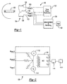
- FIG. 1 is a schematic diagram of a magnetic motor 100 whose operation can be monitored according to the invention. Note that Figures 1 and 2 are simplified for illustrative purposes and show only one pole of a multiple-pole device.
- the motor 100 includes a magnetic rotor 102, which is a permanent magnet, that rotates within a stator 104 having three phases A, B and C with corresponding coil windings 106.
- drive power electronics 107 control the current moving through the windings 106 to control the magnetic field surrounding the windings 106, causing the magnetic rotor 102 to rotate as it repels and attracts the poles in the generated magnetic field.
- FIG. 2 illustrates a wye-connected motor.
- a monitoring module 108 monitors the voltage at each phase and uses this information to determine the overall health of the motor 100.
- the magnetic rotor 102 rotates, it creates an alternating magnetic field that links the coils in the stator to induce a back EMF across each phase A, B and C.
- the typical measurements of the back EMF in this type of motor connection are made between two phase leads 103 (e.g., A-C, B-C, and A-B).
- the specific characteristics of the back EMF will vary depending on the overall health of the magnetic rotor 102, the windings 106, and any insulation (not shown) failure in the motor 100 as well as environmental conditions and motor speed.
- the back EMF across phase pairs can be measured by a voltmeter 112, which can measure either the RMS voltage or the peak-to-peak voltage.
- the monitoring module 108 also includes an optional speed sensor 114 to measure the frequency of the motor, if desired. Alternatively, the speed can be determined by the frequency and period of the back EMF trace itself, eliminating the need for a separate speed sensor. With the back EMF and motor speed information, it is possible to obtain a given back EMF response "signature" at a given condition (e.g., motor speed and temperature).
- the signature generated by the motor 100 will vary depending on the health of the motor components. For example, if the magnetic rotor 102 has been demagnetized due to, for example, environmental conditions, the resulting back EMF signature will have a lower magnitude than the back EMF of a magnet in a healthy condition. Other motor component deterioration, such as wire shorts or breakages, will also cause the signature to deviate by, for example, exhibiting a voltage imbalance between two leads.
- An analog-to-digital (A/D) converter 116 converts the analog voltage and frequency data from the voltmeter 112 and speed sensor 114 to digital data.
- the converted data is sent to a controller 118, which compares the converted data with data stored in a memory 120 to determine the health of the motor 100.
- the controller 118 can be any appropriate control device, such as a microprocessor-based device.
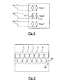
- Figure 3 illustrates an example of how the data is analyzed.
- a reference signature 150 of the motor 100 obtained at a given speed and temperature when the motor is in a normal healthy condition is stored in the memory 120.
- the motor 100 may then be periodically induced to spin freely, ideally at the same speed and temperature as when the reference signature 150 was obtained.
- the resulting measured signature 152 is then compared with the reference signature 150 to determine whether the measured signature 152 deviates from the reference by a predetermined threshold. If the measured signature 152 indicates that the electromagnetic performance of the motor has deteriorated beyond the predetermined threshold, the controller 118 activates an alert mechanism 154 that notifies the user of a pending motor fault.
- the alert mechanism 154 can be any device that conveys information to the user about the fault, such as a visual or audible warning.
- the alert mechanism 154 may also be a device that generates a digital signal to a master system to alert the system of the pending motor fault.
- the predetermined threshold may be obtained experimentally by obtaining the measured back EMF signature 152 of the motor 100 when its performance is at an unacceptable level and then setting the threshold to be a selected percentage (e.g., ten percent) higher than the signature at failure. In this way, it is possible to catch motor performance deterioration before an actual performance failure occurs, allowing a user to pro-actively address motor maintenance issues before they cause problems. This ensures that motor performance can remain consistently reliable.
- the comparison itself may be conducted by converting the raw voltage signal to an RMS voltage value and then comparing the RMS voltage value of the motor in its current operating state with the reference RMS voltage value of a healthy motor.
- the RMS voltage value corresponds to the amount of energy generated by the permanent magnet motor because the RMS voltage effectively represents the area under the curve shown in Figure 3.
- the comparison may also be conducted by digitizing the voltage trace and storing specific voltage levels vs. time points to capture and characterize the voltage waveform. The waveform, peak value, RMS value, or any other characteristic reflecting the current operating state of the motor can them be compared with a corresponding characteristic in a healthy motor.
- FIGs 4, 5 and 6 illustrate another embodiment of the invention.
- the connection between the phases is conducted in the drive power electronics 107 rather than at the windings 106.
- the phases can be tapped by the voltmeter 112 and the speed sensor 114 either as pairs or independently as individual phases.
- the voltmeter 112 and/or the speed sensor 114 measures across a lead 103 pair associated with one of the individual phases.
- Figure 6 shows one example of the traces of all three phases in relation to each other, illustrating the difference between the back EMF signature 150 of a healthy device and the back EMF signature 152 of a device with reduced capabilities.
- implementation of the invention uses information that is already available to the controller 118 (i.e., voltage, speed, temperature) and therefore does not require any new sensors or other hardware dedicated to the invention.
- the logic needed to carry out the inventive method can be easily programmed into the controller 118.
- the overall health condition of the motor 100 can be monitored to detect when service or scheduled maintenance is needed well before the system is not operationally acceptable. This periodic monitoring makes it possible to prolong the life of the motor 100 and ensure motor reliability through early problem detection and solving.
- the invention also eliminates the need to implement premature proactive maintenance or replacements in an attempt to ensure high reliability. As a result, the inventive monitoring system optimizes maintenance scheduling and minimizes overall long-term operational costs.
- a similar health monitoring scheme may be applied if the device is running as a generator as well.
- the difference between the generator and the motor is that in case of a generator, the mechanical energy is converted into an electrical energy in the form of output voltage and current.
- the back EMF can be made as a reference as a function of speed.
- the terminal voltage which is the difference of the back EMF and the impedance drop, is a function of load current. Therefore, for the generator application, the health monitoring can be done by using a method and system similar to the method and system described above, except that in this case, the back EMF, the terminal voltage, and load current are measured at a given load to establish a signature response. A measured signature is then obtained periodically during the life of the generator at the same conditions as the reference signature to check the current terminal voltage characteristics of the generator.
Landscapes
- Physics & Mathematics (AREA)
- General Physics & Mathematics (AREA)
- Control Of Motors That Do Not Use Commutators (AREA)
Applications Claiming Priority (2)
| Application Number | Priority Date | Filing Date | Title |
|---|---|---|---|
| US831873 | 2004-04-26 | ||
| US10/831,873 US7298282B2 (en) | 2004-04-26 | 2004-04-26 | Health monitoring method and system for a permanent magnet device |
Publications (1)
| Publication Number | Publication Date |
|---|---|
| EP1591798A1 true EP1591798A1 (de) | 2005-11-02 |
Family
ID=34941036
Family Applications (1)
| Application Number | Title | Priority Date | Filing Date |
|---|---|---|---|
| EP05252596A Ceased EP1591798A1 (de) | 2004-04-26 | 2005-04-26 | Zustandsüberwachungsverfahren und -vorrichtung für eine Permanentmagnetvorrichtung |
Country Status (2)
| Country | Link |
|---|---|
| US (1) | US7298282B2 (de) |
| EP (1) | EP1591798A1 (de) |
Cited By (1)
| Publication number | Priority date | Publication date | Assignee | Title |
|---|---|---|---|---|
| CN104471238A (zh) * | 2012-06-19 | 2015-03-25 | 斯堪尼亚商用车有限公司 | 用于启动电机的诊断 |
Families Citing this family (15)
| Publication number | Priority date | Publication date | Assignee | Title |
|---|---|---|---|---|
| US7545163B2 (en) * | 2006-02-22 | 2009-06-09 | Delphi Technologies, Inc. | Three phase motor diagnostics and phase voltage feedback utilizing a single A/D input |
| US7948192B2 (en) * | 2008-07-30 | 2011-05-24 | Hamilton Sundstrand Corporation | Dual redundant variable field permanent magnet dynamoelectric machine |
| US7956565B2 (en) * | 2008-07-30 | 2011-06-07 | Hamilton Sundstrand Corporation | Variable field permanent magnet dynamoelectric machine |
| TWI474023B (zh) * | 2008-12-10 | 2015-02-21 | Ind Tech Res Inst | 馬達故障診斷方法及其診斷裝置 |
| US8149551B2 (en) * | 2009-04-09 | 2012-04-03 | Hamilton Sundstrand Corporation | Systems and methods involving motor drive ground fault interrupts |
| US20110089883A1 (en) * | 2009-10-21 | 2011-04-21 | Gm Global Technology Operations, Inc. | Motor phase winding fault detection method and apparatus |
| US8362732B2 (en) * | 2010-02-02 | 2013-01-29 | GM Global Technology Operations LLC | Motor phase winding fault detection method and apparatus |
| SE536553C2 (sv) * | 2012-06-19 | 2014-02-18 | Scania Cv Ab | Diagnostisering av startsystem |
| CN103986397B (zh) * | 2014-05-19 | 2016-08-24 | 安徽中家智锐科技有限公司 | 无刷直流电机永磁体故障检测方法 |
| DE102014222162B3 (de) * | 2014-10-30 | 2015-10-15 | Volkswagen Aktiengesellschaft | Verfahren und Vorrichtung zum Betreiben einer EC-Kraftstoffpumpe |
| US10256761B2 (en) | 2016-08-31 | 2019-04-09 | Intel Corporation | Monitoring health of electrical equipment |
| CN110187275B (zh) * | 2019-06-06 | 2021-11-23 | 中车株洲电力机车研究所有限公司 | 一种永磁电机健康状态检测方法及系统 |
| DK202070331A1 (en) * | 2020-05-20 | 2021-07-21 | Vestas Wind Sys As | Virtual machine testing of electric machines using physical domain performance signatures |
| CN114999767B (zh) * | 2022-06-15 | 2022-12-23 | 浙江远鸿新能源科技有限公司 | 一种直流电机的充磁电流控制模块及方法 |
| CN115615594B (zh) * | 2022-12-19 | 2023-03-31 | 西安航天精密机电研究所 | 一种h型动压轴承电机启动力矩裕度测试方法 |
Citations (8)
| Publication number | Priority date | Publication date | Assignee | Title |
|---|---|---|---|---|
| US4893067A (en) * | 1987-05-06 | 1990-01-09 | Black & Decker Inc. | Direct current motor speed control |
| US5629870A (en) | 1994-05-31 | 1997-05-13 | Siemens Energy & Automation, Inc. | Method and apparatus for predicting electric induction machine failure during operation |
| JPH09294354A (ja) * | 1996-04-26 | 1997-11-11 | Toshiba Corp | 永久磁石モータ |
| US6199023B1 (en) | 1998-11-16 | 2001-03-06 | Geneal Electric Company | System for removing spurious signatures in motor current signature analysis |
| US6323625B1 (en) * | 1996-12-03 | 2001-11-27 | Brij B. Bhargava | Turbine/alternator on a common shaft with an associated electrical system |
| US20020097066A1 (en) | 2000-06-27 | 2002-07-25 | Yann-Guang Pan | Method for determining whether a rotor is good in magnetic induction by measuring the emf of a motor |
| US20020125895A1 (en) * | 2001-03-07 | 2002-09-12 | Nissan Motor Co., Ltd. | Insulation inspection apparatus for motor |
| US20020175674A1 (en) | 2001-05-04 | 2002-11-28 | Abbas Raftari | Permanent magnet degradation monitoring for hybrid and electric vehicles |
Family Cites Families (6)
| Publication number | Priority date | Publication date | Assignee | Title |
|---|---|---|---|---|
| US5369344A (en) * | 1992-02-28 | 1994-11-29 | Mezzatesta, Jr.; Frank | Tachometer for determining the speed of a motor |
| US5751132A (en) * | 1996-09-20 | 1998-05-12 | Automeg, Inc. | Electric motor monitoring circuit |
| US5917428A (en) * | 1996-11-07 | 1999-06-29 | Reliance Electric Industrial Company | Integrated motor and diagnostic apparatus and method of operating same |
| US5938529A (en) * | 1997-03-17 | 1999-08-17 | Unislot, Inc. | Reel type slot machine having stepper motor monitoring system |
| US7091724B2 (en) * | 2003-07-23 | 2006-08-15 | Deka Products Limited Partnership | Model-based fault detection in a motor drive |
| JP4053501B2 (ja) * | 2004-01-13 | 2008-02-27 | ファナック株式会社 | モータ駆動装置 |
-
2004
- 2004-04-26 US US10/831,873 patent/US7298282B2/en not_active Expired - Lifetime
-
2005
- 2005-04-26 EP EP05252596A patent/EP1591798A1/de not_active Ceased
Patent Citations (8)
| Publication number | Priority date | Publication date | Assignee | Title |
|---|---|---|---|---|
| US4893067A (en) * | 1987-05-06 | 1990-01-09 | Black & Decker Inc. | Direct current motor speed control |
| US5629870A (en) | 1994-05-31 | 1997-05-13 | Siemens Energy & Automation, Inc. | Method and apparatus for predicting electric induction machine failure during operation |
| JPH09294354A (ja) * | 1996-04-26 | 1997-11-11 | Toshiba Corp | 永久磁石モータ |
| US6323625B1 (en) * | 1996-12-03 | 2001-11-27 | Brij B. Bhargava | Turbine/alternator on a common shaft with an associated electrical system |
| US6199023B1 (en) | 1998-11-16 | 2001-03-06 | Geneal Electric Company | System for removing spurious signatures in motor current signature analysis |
| US20020097066A1 (en) | 2000-06-27 | 2002-07-25 | Yann-Guang Pan | Method for determining whether a rotor is good in magnetic induction by measuring the emf of a motor |
| US20020125895A1 (en) * | 2001-03-07 | 2002-09-12 | Nissan Motor Co., Ltd. | Insulation inspection apparatus for motor |
| US20020175674A1 (en) | 2001-05-04 | 2002-11-28 | Abbas Raftari | Permanent magnet degradation monitoring for hybrid and electric vehicles |
Non-Patent Citations (2)
| Title |
|---|
| "DSP Solutions for BLDC Motors", BPRA055, 1 March 1997 (1997-03-01), pages 1 - 20, XP055013611, Retrieved from the Internet <URL:http://www.ti.com/lit/an/bpra055/bpra055.pdf> [retrieved on 20110915] * |
| JIANWEN SHAO ET AL: "A novel microcontroller-based sensorless brushless DC (BLDC) motor drive for automotive fuel pumps", 1 November 2003, IEEE TRANSACTIONS ON INDUSTRY APPLICATIONS, IEEE SERVICE CENTER, PISCATAWAY, NJ, US, PAGE(S) 1734 - 1740, ISSN: 0093-9994, XP011103830 * |
Cited By (2)
| Publication number | Priority date | Publication date | Assignee | Title |
|---|---|---|---|---|
| CN104471238A (zh) * | 2012-06-19 | 2015-03-25 | 斯堪尼亚商用车有限公司 | 用于启动电机的诊断 |
| CN104471238B (zh) * | 2012-06-19 | 2016-08-24 | 斯堪尼亚商用车有限公司 | 用于启动电机的诊断 |
Also Published As
| Publication number | Publication date |
|---|---|
| US20050237212A1 (en) | 2005-10-27 |
| US7298282B2 (en) | 2007-11-20 |
Similar Documents
| Publication | Publication Date | Title |
|---|---|---|
| US7298282B2 (en) | Health monitoring method and system for a permanent magnet device | |
| US10042011B2 (en) | Method to detect or monitor the demagnetization of a magnet | |
| CA2761344C (en) | System and method for synchronous machine health monitoring | |
| EP2296265B1 (de) | System zur Erkennung von Generatorwicklungsfehlern | |
| CN105656250A (zh) | 交流发电机转子控制器 | |
| US20130030742A1 (en) | Method and system for monitoring a synchronous machine | |
| CN103947065A (zh) | 永磁体发电机的保护 | |
| KR102109310B1 (ko) | 동기식 발전기 제어, 발전기 시스템 및 선박 에너지 시스템 | |
| JP2023019945A (ja) | 発電機、コイル素子、モータ及び航空機 | |
| EP2510614B1 (de) | Eine elektrische maschine | |
| CN110323898B (zh) | 交流发电机转子控制器 | |
| KR101501718B1 (ko) | 영구자석 발전기 자동 제동 제어장치 | |
| RU2525852C1 (ru) | Цепь электропитания летательного аппарата, включающая в себя асинхронную машину | |
| RU2766958C1 (ru) | Устройство защиты якорной обмотки машин переменного тока от коротких замыканий | |
| KR102561896B1 (ko) | 사용자 맞춤형의 다채널을 이용한 전압조정기를 포함하는 비상용 디젤 발전기 | |
| Neti et al. | Motor current signature analysis during accelerated life testing of form wound induction motors | |
| KR102561895B1 (ko) | 고장표시와 조치 기능이 구비된 안전을 위한 전압조정기를 포함하는 비상용 디젤 발전기 | |
| KR101046328B1 (ko) | 삼상 교류 전동기 고정자 코어 상태 진단 장치, 방법, 및 상기 방법을 실행시키기 위한 컴퓨터 판독 가능한 프로그램을 기록한 매체 | |
| KR200344402Y1 (ko) | 발전기 회전자 접지검출장치의 검사장치 | |
| US10749398B2 (en) | High torque motor failsafe operating system | |
| WO2025095931A1 (en) | Electrical circuit for energy harvesting and electric machine sensing | |
| Bogusz et al. | Failure mode study in switched reluctance machines in the generator mode |
Legal Events
| Date | Code | Title | Description |
|---|---|---|---|
| PUAI | Public reference made under article 153(3) epc to a published international application that has entered the european phase |
Free format text: ORIGINAL CODE: 0009012 |
|
| AK | Designated contracting states |
Kind code of ref document: A1 Designated state(s): AT BE BG CH CY CZ DE DK EE ES FI FR GB GR HU IE IS IT LI LT LU MC NL PL PT RO SE SI SK TR |
|
| AX | Request for extension of the european patent |
Extension state: AL BA HR LV MK YU |
|
| 17P | Request for examination filed |
Effective date: 20060330 |
|
| AKX | Designation fees paid |
Designated state(s): AT BE BG CH CY CZ DE DK EE ES FI FR GB GR HU IE IS IT LI LT LU MC NL PL PT RO SE SI SK TR |
|
| STAA | Information on the status of an ep patent application or granted ep patent |
Free format text: STATUS: THE APPLICATION HAS BEEN REFUSED |
|
| 18R | Application refused |
Effective date: 20110927 |