EP1591360B1 - Apparatus for handling and packaging friable tablets - Google Patents
Apparatus for handling and packaging friable tablets Download PDFInfo
- Publication number
- EP1591360B1 EP1591360B1 EP04025128A EP04025128A EP1591360B1 EP 1591360 B1 EP1591360 B1 EP 1591360B1 EP 04025128 A EP04025128 A EP 04025128A EP 04025128 A EP04025128 A EP 04025128A EP 1591360 B1 EP1591360 B1 EP 1591360B1
- Authority
- EP
- European Patent Office
- Prior art keywords
- tablets
- dosage forms
- assembly
- packaging
- laning
- Prior art date
- Legal status (The legal status is an assumption and is not a legal conclusion. Google has not performed a legal analysis and makes no representation as to the accuracy of the status listed.)
- Expired - Lifetime
Links
- 238000004806 packaging method and process Methods 0.000 title claims description 34
- 239000002552 dosage form Substances 0.000 claims description 52
- 239000005022 packaging material Substances 0.000 claims description 22
- 238000011144 upstream manufacturing Methods 0.000 claims description 3
- 238000007789 sealing Methods 0.000 description 23
- 239000000463 material Substances 0.000 description 11
- 230000032258 transport Effects 0.000 description 5
- 230000006378 damage Effects 0.000 description 3
- 230000008901 benefit Effects 0.000 description 2
- 238000010438 heat treatment Methods 0.000 description 2
- 239000004033 plastic Substances 0.000 description 2
- 229920003023 plastic Polymers 0.000 description 2
- 239000007787 solid Substances 0.000 description 2
- 230000007704 transition Effects 0.000 description 2
- 229910000831 Steel Inorganic materials 0.000 description 1
- 239000004809 Teflon Substances 0.000 description 1
- 229920006362 Teflon® Polymers 0.000 description 1
- 238000009825 accumulation Methods 0.000 description 1
- 239000004480 active ingredient Substances 0.000 description 1
- 229910052782 aluminium Inorganic materials 0.000 description 1
- XAGFODPZIPBFFR-UHFFFAOYSA-N aluminium Chemical compound [Al] XAGFODPZIPBFFR-UHFFFAOYSA-N 0.000 description 1
- 230000000712 assembly Effects 0.000 description 1
- 238000000429 assembly Methods 0.000 description 1
- 239000002775 capsule Substances 0.000 description 1
- 238000001514 detection method Methods 0.000 description 1
- 239000003814 drug Substances 0.000 description 1
- 239000000428 dust Substances 0.000 description 1
- 230000000694 effects Effects 0.000 description 1
- 229920001971 elastomer Polymers 0.000 description 1
- 229920002313 fluoropolymer Polymers 0.000 description 1
- 239000004811 fluoropolymer Substances 0.000 description 1
- 239000011888 foil Substances 0.000 description 1
- 229910052751 metal Inorganic materials 0.000 description 1
- 239000002184 metal Substances 0.000 description 1
- 150000002739 metals Chemical class 0.000 description 1
- 239000000203 mixture Substances 0.000 description 1
- 239000008188 pellet Substances 0.000 description 1
- 239000006187 pill Substances 0.000 description 1
- 239000012858 resilient material Substances 0.000 description 1
- 230000004044 response Effects 0.000 description 1
- 229920002379 silicone rubber Polymers 0.000 description 1
- 239000004945 silicone rubber Substances 0.000 description 1
- 239000010959 steel Substances 0.000 description 1
- 239000003826 tablet Substances 0.000 description 1
- BFKJFAAPBSQJPD-UHFFFAOYSA-N tetrafluoroethene Chemical compound FC(F)=C(F)F BFKJFAAPBSQJPD-UHFFFAOYSA-N 0.000 description 1
- 230000000007 visual effect Effects 0.000 description 1
Images






Classifications
-
- B—PERFORMING OPERATIONS; TRANSPORTING
- B65—CONVEYING; PACKING; STORING; HANDLING THIN OR FILAMENTARY MATERIAL
- B65B—MACHINES, APPARATUS OR DEVICES FOR, OR METHODS OF, PACKAGING ARTICLES OR MATERIALS; UNPACKING
- B65B35/00—Supplying, feeding, arranging or orientating articles to be packaged
- B65B35/30—Arranging and feeding articles in groups
- B65B35/44—Arranging and feeding articles in groups by endless belts or chains
-
- B—PERFORMING OPERATIONS; TRANSPORTING
- B65—CONVEYING; PACKING; STORING; HANDLING THIN OR FILAMENTARY MATERIAL
- B65B—MACHINES, APPARATUS OR DEVICES FOR, OR METHODS OF, PACKAGING ARTICLES OR MATERIALS; UNPACKING
- B65B5/00—Packaging individual articles in containers or receptacles, e.g. bags, sacks, boxes, cartons, cans, jars
- B65B5/10—Filling containers or receptacles progressively or in stages by introducing successive articles, or layers of articles
- B65B5/101—Filling containers or receptacles progressively or in stages by introducing successive articles, or layers of articles by gravity
- B65B5/103—Filling containers or receptacles progressively or in stages by introducing successive articles, or layers of articles by gravity for packaging pills or tablets
Definitions
- the present invention relates to an assembly for guiding pharmaceutical dosage forms in a packaging assembly in accordance with the preamble of claim 1.
- Such an assembly is known from DE-A-4406089 .
- the present invention can be applied to systems or assemblies for packaging essentially any dosage form.
- Such systems may include a forming device such as a tablet press, an infeed structure, a laning structure, robotic devices for handling or carrying dosage forms, and a packaging machine.
- a series of conveyor belts and ramps transport the dosage forms through the packaging system. After the dosage forms are made, they proceed through the system and are controlled and organized for receipt by a packaging machine.
- a robotic handler may be used to transport dosage forms to the packaging machine. If the system packages dosage forms into blister packages, a robotic handler may be used to transport dosage forms to a sheet of packaging material, which will be sealed with a second sheet of material to form packages of the dosage forms.
- the dosage forms travel through the packaging system rapidly and in large volumes. As many as 800 to 1,440 tablets per minute, or more, may be assembled into 240 packages of tablets per minute, or more. Hence, a displaced machine part, one of the dosage forms, or other debris anywhere in the system can cause dosage forms to break and improperly formed packages. Some systems must be shut down so that the jammed product or other debris may be cleared manually. This results in a loss of the product in large numbers before the system can be interrupted and the problem remedied.
- the present invention provides an assembly for guiding pharmaceutical dosage forms in a packaging assembly, comprising a surface movable in a downstream direction, a laning structure extending in a lateral direction transverse to the downstream direction and defining a plurality of laterally spaced lanes extending in the downstream direction.
- the assembly also comprises guide wall structures including a curved portion and a wall structure defining a plenum upstream of the laning structure.
- the curved portion guides the dosage forms carried by said surface so that dosage forms enter the plenum structure at a plenum entry adjacent a first side of the laning structure and travel laterally toward a second side of the laning structure before entering the lanes.
- the assembly preferably includes a form handling device for receiving dosage forms and transporting dosage forms from the laning structure to a packaging device.
- the packaging device may include a top plate and a bottom plate for engaging a packaging material and a lid stock therebetween to seal the packaging material and lid stock together, forming packaged dosage forms.
- the assembly may include a top plate and bottom plate including a plurality of blocks and a base for floatably supporting the blocks.
- the lanes may have a downstream end and the assembly may further comprise a dump gate at the downstream end, having an open position and a closed position.
- a timed controller may be provided for opening the dump gate after the handling device receives dosage forms so that debris will be carried downstream out of the laning structure.
- FIG. 1-9 One embodiment of an assembly for handling and packaging dosage forms is depicted in Figs. 1-9.
- An infeed structure 22, a laning structure 35 and a plenum structure 32 extending between the infeed structure and the laning structure arrange dosage forms such as tablets into rows so that they can be arranged into packages.
- the dosage forms handled by the assembly may be any type of dosage form, including tablets, capsules, pills, pellets, and other forms.
- the assembly is particularly useful for fragile dosage forms.
- the tablets are transported throughout the assembly on a movable surface or conveyance device, such as a conventional conveyor belt.
- a rotating drum or disk may also be used.
- the conveyor belt is driven by any conventional means 13 such as an electric motor or other conventional drive so that the upper run 10 of the belt moves in a downstream direction 11.
- the motor is controlled by a switch and a control device for starting and stopping the conveyor belt and varying the speed of the conveyor belt.
- the conveyor belt is adjacent a tablet press 12 which forms tablets 15.
- the tablets travel from the tablet press down a ramp 21 to the conveyor belt.
- the ramps, as well as the other surfaces used in the assembly which contact the tablets are preferably made of a smooth material which will not interfere with the sliding of the tablets to the next stage of the system. Many plastics and other materials may be used.
- the ramps and other surfaces may be coated with a smooth material such as a fluoropolymer of the type sold under the trademark TEFLON to promote the sliding of the tablets.
- the upper run 10 of the belt receives tablets 15 from the tablet press 12 and conveys the tablets in the downstream direction 11.
- the infeed structure 22 includes a guide wall structure 14 is disposed over the upper run 10 of the conveyor belt, and guides the tablets as they move downstream with the belt.
- the speed of the conveyor belt is variable in a range from about 0.2 to 0.5 m/s (40 to 100 feet per minute).
- the guide wall structure 14 defines a channel 20 over the upper run 10 of the belt extending from the tablet press to the laning structure.
- the channel 20 has a top wall 17, a first side wall 18, a second sidewall 19 and an open bottom 16, as shown in Fig. 5.
- the open bottom 16 of the channel 20 faces toward the upper run 10 of the conveyor belt, so that tablets 15 disposed on the belt are moved downstream within the channel 20 and are guided by the top wall 17, first sidewall 18, and second sidewall 19.
- the guide wall structure 14 includes a guide portion 25, having an entry 26 adjacent the tablet press 12 and an exit 27 adjacent a plenum structure 32.
- the guide wall structure also defines the plenum structure 32, having a plenum entry 28 adjacent the exit 27 and a transitional portion 33, as depicted in Figs. 2-4.
- the transitional portion guides tablets into the laning structure which is typically wider than the guide portion 25, which causes tablets to back up to the juncture between the guide portion and transitional portion.
- the guide portion 25 includes a curved portion 45 of the guide wall structure 14 provided for guiding the tablets into the wider transitional portion 33 of the plenum structure 32.
- the transitional portion 33 is adjacent an inlet end 34 of the laning structure 35.
- the laning structure 35 has a first side 46 and a second side 47 and includes a series of finger members 36.
- the finger members 36 extend in a downstream direction 11 from the inlet end 34 of the laning structure to a downstream end 38 of the laning structure 35.
- the finger members 36 define lanes 40 which are spaced from each other in a lateral direction 43 transverse to the downstream direction 11. The lanes arrange the tablets into rows 42.
- the dimensions of the guide wall structure depends upon the size of the tablet or other dosage form.
- the embodiment shown in Figs. 1-9 is designed to handle tablets having a 6.4 mm (1/4") diameter, but the dimensions provided below may be varied for tablets having a 17.5 mm (11/16)", 12.7 mm (1/2"), or 15.9 mm (5/8") diameter, or other sizes and types of dosage forms.
- the thickness of the tablets range from about 2.5 mm (0.100") to 8.1 mm (0.320").
- the channel 20 in the embodiment of Figs. 1-9 has a width of 149 mm (5-7/8") at the section shown in Fig.
- the curved portion 45 has the same width as the channel 20 and is defined by the guide wall structure 14.
- the transition portion 33 in the embodiment of Fig. 4 has a width of 378 mm (14-7/8"). The width of the transitional portion is the dimension transverse to the downstream direction 11.
- the lanes 40 depicted in Fig. 4, extend in the downstream direction 11 and are spaced apart from one another in the lateral direction 43.
- the finger members 36 of the laning structure 35 preferably comprise vibrating guide members 36 which assist in moving the tablets downstream.
- the lanes for the 6.4 mm (1/4") tablets are 15.9 mm (5/8") wide and 308 mm (12-1/8") long.
- the vibrating members are attached to a selectively operable actuator or actuators 78 such as a solenoid, electric motor operated actuator, hydraulic cylinder or, most preferably, an air cylinder for vibrating the guide members 36.
- the vibrating members agitate the tablets so that they move downstream within the lanes to the downstream end 38.
- the vibrating members which define the lanes are preferably formed with an aperture separating two side bars, so that each bar can be replaced in the event that they become warped or otherwise damaged.
- a dump gate 80 is positioned at the downstream end 38 of the laning structure 35. Adjacent the downstream end 38 is a tablet pickup area 82 of the lanes 40. Adjacent the dump gate on a side of the dump gate opposite the pickup area 82, is a discard ramp 81. In the closed position illustrated in Fig. 4, the dump gate blocks the downstream end 38 of each lane 40.
- the downstream motion of the conveyor belt beneath the laning structure carries tablets downstream until the leading or most downstream tablet in each lane stops against the closed dump gate.
- the laning structure includes a surface beneath the lanes which is sloped in the downstream direction 11 to encourage tablets and other debris to move toward the downstream end 38 of the laning structure 35.
- a form handling device 38 is disposed above the pickup area 82 of the lanes 40.
- the form handling device 38 comprises a robotic handler including an array of finger-like channels 64, a soft rubber suction cup 65 on each such finger 64, and a vacuum pump connected to the finger-like channels 64 for applying suction through the suction cups so that the suction cups can receive and lift the tablets 15.
- the robotic handler 83 receives the tablets and transports them to the packaging machine, where the tablets are released by releasing the vacuum.
- other "pick and place" form handlers are used to transport tablets from pickup area 82 to the packaging machine.
- the array of finger-like channels 64 preferably comprises a two-dimensional array of the channels 64, arranged in a carriage assembly connected to an arm 66 rotatable around a vertical axis.
- a suction cup 65 of each channel 64 corresponds to a tablet arranged in the pickup area 82 of the lanes, as depicted in Fig. 4A.
- the arm 66 of the robotic hander After lifting the tablets, the arm 66 of the robotic hander carries the tablets to the packaging machine.
- the dump gate is attached to a selectively operable actuator 79 such as a solenoid, electric motor operated actuator, hydraulic cylinder or, most preferably, an air cylinder for opening and closing the dump gate.
- a selectively operable actuator 79 such as a solenoid, electric motor operated actuator, hydraulic cylinder or, most preferably, an air cylinder for opening and closing the dump gate.
- a number of air cylinder models may be used and the type of air cylinder depends upon the size tablet being packaged.
- the actuator is linked to a control device such as a mechanical, fluidic, electronic or electromechanical controller of known type which is also linked to the robotic handler.
- the controller is a programmable, computer actuated controller having functions controlled by software.
- a detection system with three (3) sensors spaced along the infeed structure 22 is provided for detecting a backup of tablets in the guide wall structure 14.
- the first sensor 51 is located adjacent the exit 27 of the guide portion proximate to the curved portion 45, as depicted in Fig. 2.
- the first sensor 51 provides an indication that the curved portion 45 is clear and to turn on the tablet press 12 and commence flow of tablets through the packaging system.
- the second sensor 52 produces an indication that the tablets have backed up from the exit 27 to the second sensor 52 and that the tablet press rate should be reduced.
- the third sensor 53 located at the entry 26 of the guide portion 25, produces an indication that the tablets backed up to the third sensor 53 and to turn off the tablet press.
- Software and computer hardware may be provided to receive the indications from the sensors and to control the operation of the tablet press.
- preferred embodiments include a guide wall structure 14 having vacuum holes 50 for dedusting the channel 20.
- a vacuum is preferably attached to the top wall 17 of the guide wall structure 14 for this purpose.
- the guide wall structure 14 is preferably formed from a plastic material which is also preferably transparent for visual observation of the tablets transported within the system.
- tablets are carried in the downstream direction 11 on the upper run 10 of the conveyor belt, through the guide wall structure 14.
- the tablets are guided through the curved portion 45 to the plenum structure 32 and travel through the transitional portion 33.
- the tablets In the transitional portion 33, the tablets generally travel from the first side 46 in the lateral direction 43 toward the second side 47 of the laning structure 35 before entering the lanes 40.
- the tablets Upon entering the lanes, the tablets travel in the downstream direction 11.
- a row 42 of tablets stack up in upstream-to-downstream order within the tablet pickup area 82 of each lane 40.
- the form handling device 83 engages the tablets 15 stacked within the various lanes 40 and lifts a predetermined number of tablets out of each lane during each cycle of operation.
- the operation of the embodiment having the robotic tablet handler will now be described. As depicted in Fig. 4A, the robotic tablet handler descends from a first position 83A to a second position 83b to receive the tablets within the lanes 40. For ease of illustration, only a few of the lanes 40 depicted in Fig. 4 are depicted in Fig. 4A.
- the vacuum is applied and the tablets are received within the suction cups 65.
- the arm 66 raises the array of finger-like channels 64 and suction cups 65 to position 83a and rotates 180° to position 83C, over the packaging machine 90.
- the tablet 15b immediately after the last tablet 15a lifted by the robotic handler 83 then becomes the leading tablet of the next group to be received be the robotic tablet hander 83.
- the controller operates the actuator in synchronism with the handler 83 or other form handling device so that the dump gate 80 opens after the handler 83 has engaged a group of tablets and remains open for a preselected open time after the handler 83 has lifted that group of tablets out of the laning structure 35. While the dump gate is open, debris accumulated in each lane moves downstream, past the dump gate 80 and down the discard ramp 81, where debris is collected for disposal. The next group of tablets move downstream to the downstream end 38.
- the open time of the dump gate 80 is selected so that it is just slightly less than the time required for the leading tablet of the next group to reach the downstream end 38 of the lane 40. Thus, the dump gate 80 returns to the closed position just before the leading tablet (for example, tablet 15b) of the next group arrives at the dump gate 80. This cycle of operations is repeated.
- the dump date may be manually operated in some embodiments, which is less preferred. Attempts have been made heretofore to use a dump gate which is manually actuated by an operator in response to visible accumulation of debris in the lanes, or which is actuated at some lengthy intervals. Where the dump gate is manually operated, debris such as tablets or parts of tablets missed by the robotic tablet handler interfere with the next set of tablets preceding to the pickup area 82 through the lanes 40. Breakage of tablets occurs in the laning area before a human operator is alerted who can operate the dump gate. Also, when the manually operated dump gate is held open, some good tablets pass out of the dump gate and are wasted. By contrast, in the preferred systems according to this aspect of the invention, debris is cleared during each cycle of the handler, without wasting good tablets.
- inventions include an infeed structure, a plenum structure and a laning structure adapted to different sized tablets and different types of dosage forms.
- Certain preferred embodiments also include a member 60, preferably having a triangular shape, at the juncture of the guide portion 25 and the plenum structure 32.
- the triangle 60 alleviates jamming of the tablets at this juncture. It has been found that this triangular member 60 is not required for 6.4 mm (1/4") tablets in the embodiment of Figs. 1-9, but is preferred for larger tablets. For example, in packaging 12.7 mm (1/2") tablets, a stationary triangular member is preferably used to alleviate jamming.
- a triangular member which is spring-loaded is preferably used.
- the triangular member depicted in Figs. 10 and 11, has a first leg 61 and a second leg 62 facing upstream and a third leg 63 facing downstream, facing the laning structure 35.
- the spring-loaded triangular member 60 is moveable from side to side in traverse directions 71 and 72 shown in Fig. 11, transverse to the downstream direction 11.
- the triangle is biased in a central position 70 by a biasing means 73, including a spring or other conventional biasing devices.
- the tablets bounce off the triangle, which alleviates jamming of the tablets in the plenum entry 28.
- Tablets entering the plenum entry may slide along the first leg 61 and second leg 62 and proceed to the transitional portion 33. However, in the event that tablets 15 begin to jam up, the tablets apply a small force upon the triangular member, which compresses the biasing device or spring 73. As shown in Fig. 11, the triangle may be moved to one side or the other to offset positions 70a or 70b. The spring reacts, relieving the force of the tablets. The compressibility of the spring must be such that the tablets are not broken.
- a packaging device for sealing the tablets into packages 110 is depicted in Figs. 7-9. After the tablets are sealed into packages, the packages are cut into separate cards which are arranged into boxes.
- the packaging device 90 includes a sealing machine 91 for forming packaged dosage forms.
- the packages are comprised of first and second sheets of packaging material, preferably foil laminate, which are sealed together in the sealing machine.
- An example of this type of packaging machine is a Clockner blister-forming machine. Model No. CP11.4 may be used.
- Blisters 111 which are essentially cup-shaped depressions in the packaging material, have been provided in at least one of the sheets for holding the tablets. In the finished package, which is depicted in Fig. 6, each tablet occupies a pocket formed by the blisters 111.
- blister packages of the type described concerning certain embodiments of copending, commonly assigned United States patent application Serial No. 09/053,298, filed April 1, 1998 may be used.
- the packaging device 90 is generally of the type known as a "form, fill and seal" machine.
- the machine forms a web of a packaging material into blisters, whereupon the form handler 83 places the tablets in the blisters.
- each suction cup 65 of the robotic handler corresponds to a blister 111 in the packaging material, as depicted in Fig. 4A.
- the robotic handler received tablets at the pickup area 82 and rotates 180° from position 83C to position 83D, toward the packaging material 112 on support 114. After the arm 66 lowers to the packaging material, the tablets are release into blisters 111.
- the packaging material advances along a conveyor belt, series of rollers or a similar conveyance device 68 to a sealing machine through a series of checking systems which ensure that the first sheet is free from displaced tablets and debris prior to reaching the sealing machine.
- the packaging material is sealed to a web or sheet of lid stock so that the lid stock closes the blisters and holds the tablets in the blisters.
- the sealing machine includes a top and bottom plate.
- the top and bottom plates of the sealing machine each have sealing faces, for engaging the lid stock and packaging material, respectively.
- blister cavities 115 are provided in the sealing face 116 of the bottom plate 113.
- the top plate may include blister cavities, as well.
- the plates preferably have registration markers 17 so that the top and bottom plates can be properly aligned. At least one of the plates, typically the top plate, is heated so that a heat-activated material in the packaging material or lid stock seals the tablet package when the top and bottom plates are brought into engagement. Most preferably, the bottom plate is also heated.
- the heaters are connected to controllers for controlling the heating of the plates in the conventional manner.
- the web of the packaging material is transferred from support 114 to the sealing face 116 of the bottom plate 113 so that the blisters 111 rest in the blister cavities 115 of the bottom plate 113.
- the lid stock is placed on the packaging material, overlying the tablets in the blisters and the sealing machine urges the top plate and bottom plate together, so that these plates engage the package material and lid stock therebetween.
- the top and bottom plates are brought together to seal the packaging material.
- sealing occurs according to three (3) parameters: heat, pressure and time.
- At least the bottom plate is designed with recessed regions 120 depicted in Fig. 7.
- the recessed regions apply no pressure to the blister pack material and the sealing face 116 comprises relatively raised regions where the seal is to be formed. This feature focuses the force and heat of the sealing device on the portions of the blister pack where sealing is desired.
- the plates are disengaged and the sealed blister pack 110 is transported to a blister pack card punch and thereafter to a cartoner for arrangement in boxes.
- Fig. 6 depicts a blister package for 12.7 mm (1/2") tablets.
- At least one of the top and bottom plates is designed to evenly distribute the force and heat of the sealing machine along the sealing faces of the plates.
- the present invention addresses this problem by providing, rather than one continuous bottom plate 113, a plate comprised of a plurality of blocks 122 which can move with respect to one another over a range of motion.
- a plate comprised of a plurality of blocks 122 which can move with respect to one another over a range of motion.
- four movable blocks 122 are provided.
- Each block 122 depicted in Fig. 9, has a rear face 123 opposite the sealing face 116 and a circular depression 125 in the rear face.
- Each block also has a compartment cut out for heaters which communicate with controls for heating the plate, as discussed above.
- the blocks 122 are formed from metals such as steel, aluminum or the like which are selected according to conventional criteria such as wear resistance and good heat transfer.
- Each block 122 rests on a ball-like member 126, depicted in Fig. 8, which is attached to a base 128 so that the ball 126 is engaged by the circular depression 125 and each block 122 is floatably supported by the base 128.
- the spacing of the blocks 122 on the base accommodates individual tilting of each block with respect to the horizontal plane.
- each block 122 is free to tilt around any horizontal axis. This design has the benefit of achieving better sealing in the tablet packages.
- the various blocks constituting the bottom plate 122 tilt and adjust to achieve an evenly distributed pressure over the blister pack material. After a predetermined sealing time, the plates are released from the package 110, which proceeds to the cartoner.
- each block can be mounted to the base by a pad of a resilient material such as a high-temperature silicone rubber, or by a set of springs, so that each block is free to move relative to the base in a limited range of tilting movement.
- a dual-gimbal mount wherein each block is pivotally mounted to a gimbal frame for tilting movement around a first horizontal axis, and the gimbal frame is pivotally mounted to the base for tilting movement around a second horizontal axis perpendicular to the first horizontal axis.
- each block can be mounted to the base by a pad of a resilient material such as a high-temperature silicone rubber, or by a set of springs, so that each block is free to move relative to the base in a limited range of tilting movement.
- the bottom plate has individual blocks, whereas the top plate is a unitary, solid part.
- the reverse arrangement with a solid bottom plate and a top plate composed of movable parts, can also be employed.
- both plates can be formed with movable parts.
- An assembly for handling and packaging pharmaceutical dosage forms may include:
- said timed controller further comprises a computer communicating with said form handling device and said dump gate.
- the assembly may comprise a guide wall structure defining said guide portion and including a curved portion.
- said guide wall structure also defines said plenum structure, said plenum structure including a plenum entry and said guide wall structure being shaped to guide dosage forms so that dosage forms enter said plenum structure at said plenum entry adjacent a first side of said laning structure and travel in a lateral direction transverse to said downstream direction toward a second side of said laning structure before entering said lanes.
- said curved portion includes a member adjacent said plenum entry for relieving jamming of dosage forms.
- said member comprises a movable member and further comprising a biasing means for vibrating said movable member to agitate dosage forms.
- said laning structure includes a surface for supporting dosage forms, said surface sloping in said downstream direction to said dump gate so that debris is carried out of said laning structure by said surface when the dump gate is in the open position.
- the packaging device may comprise a top plate and a bottom plate for engaging a packaging material and a lid stock therebetween to seal said packaging material and said lid stock to one another, wherein at least one of said top plate and said bottom plate is comprised of a plurality of blocks and a base for supporting said plurality of blocks thereon, said blocks being floatably supported by said base and individually movable with respect to the base, for evenly distributing pressure applied to said package material and said lid stock by said top and bottom plates.
- each of said blocks has a first surface on which said packaging material is engaged, and wherein each of said blocks is free to tilt relative to said base in all directions.
- said base includes a ball-like member for each said block, each said block including a circular cavity formed thereon at a second surface of each said block opposite said first surface for receiving said ball-like member.
- At least one of said top plate and said bottom plate is heated for sealing said packaging material and said lid stock together.
- the present invention can be applied in the packaging of pharmaceuticals.
Landscapes
- Engineering & Computer Science (AREA)
- Mechanical Engineering (AREA)
- Basic Packing Technique (AREA)
- Medical Preparation Storing Or Oral Administration Devices (AREA)
Description
- The present invention relates to an assembly for guiding pharmaceutical dosage forms in a packaging assembly in accordance with the preamble of claim 1. Such an assembly is known from
DE-A-4406089 . - The present invention can be applied to systems or assemblies for packaging essentially any dosage form. Such systems may include a forming device such as a tablet press, an infeed structure, a laning structure, robotic devices for handling or carrying dosage forms, and a packaging machine. A series of conveyor belts and ramps transport the dosage forms through the packaging system. After the dosage forms are made, they proceed through the system and are controlled and organized for receipt by a packaging machine. A robotic handler may be used to transport dosage forms to the packaging machine. If the system packages dosage forms into blister packages, a robotic handler may be used to transport dosage forms to a sheet of packaging material, which will be sealed with a second sheet of material to form packages of the dosage forms.
- The dosage forms travel through the packaging system rapidly and in large volumes. As many as 800 to 1,440 tablets per minute, or more, may be assembled into 240 packages of tablets per minute, or more. Hence, a displaced machine part, one of the dosage forms, or other debris anywhere in the system can cause dosage forms to break and improperly formed packages. Some systems must be shut down so that the jammed product or other debris may be cleared manually. This results in a loss of the product in large numbers before the system can be interrupted and the problem remedied.
- The foregoing problems are exacerbated where the dosage forms are particularly susceptible to damage. This is true for packaging systems for relatively soft tablets. Such soft tablets include certain embodiments described in commonly assigned
U.S. Patent Nos. 5,178,878 and5,223,264 . These tablets include, in addition to the active ingredients, an effervescent composition so that when the tablet is orally administered to a patient, it disintegrates. The tablets are very soft with a hardness typically below about 20 Newtons and in some cases below 10 Newtons. As a result, the packaging system must take into account the fragile nature of the product by providing means for avoiding jamming and backing up within the system and adequate arrangement of the product for packaging. Despite efforts in the art, still further improvements would be desirable. - It is the object of the present invention to provide a transition between the infeed structure and the laning structure which is shaped to prevent jamming or a bottleneck effect in this transitional area which may result in damage to or destruction of the dosage forms.
- The present invention provides an assembly for guiding pharmaceutical dosage forms in a packaging assembly, comprising a surface movable in a downstream direction, a laning structure extending in a lateral direction transverse to the downstream direction and defining a plurality of laterally spaced lanes extending in the downstream direction. The assembly also comprises guide wall structures including a curved portion and a wall structure defining a plenum upstream of the laning structure. The curved portion guides the dosage forms carried by said surface so that dosage forms enter the plenum structure at a plenum entry adjacent a first side of the laning structure and travel laterally toward a second side of the laning structure before entering the lanes. The assembly preferably includes a form handling device for receiving dosage forms and transporting dosage forms from the laning structure to a packaging device. The packaging device may include a top plate and a bottom plate for engaging a packaging material and a lid stock therebetween to seal the packaging material and lid stock together, forming packaged dosage forms. The assembly may include a top plate and bottom plate including a plurality of blocks and a base for floatably supporting the blocks. The lanes may have a downstream end and the assembly may further comprise a dump gate at the downstream end, having an open position and a closed position. A timed controller may be provided for opening the dump gate after the handling device receives dosage forms so that debris will be carried downstream out of the laning structure.
- These and other features, aspects, and advantages of the present invention will become better understood with regard to the following description, appended claims and accompanying drawings, where:
- Fig. 1 is a schematic elevation of an assembly for handling and packaging pharmaceutical dosage forms;
- Fig. 2 is a schematic top plan view of an infeed structure for the embodiment of Fig. 1;
- Fig. 3 is a detail of the view of Fig. 2 showing a part of the infeed structure in the embodiment of Figs. 1-2;
- Fig. 4 is a schematic top plan view of a laning structure in accordance with the embodiment of Figs. 1-3;
- Fig. 4A is a sectional view of a preferred form handler in the embodiment of Figs. 1-4;
- Fig. 5 is a cross section taken along line 5-5 in Fig. 3;
- Fig. 6 is a plan view of a package which may be formed in the apparatus in accordance with the embodiment of the invention of Figs. 1-5;
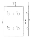
- Fig. 7 is a top plan view of a bottom plate in accordance with another aspect of the invention, in the embodiment of Figs. 1-6;
- Fig. 7A is a front elevational view of the plate of Fig. 7;
- Fig. 8 top plan view of a base for the plate of Figs. 7-7A;
- Fig. 8A is a front elevational view of the base of Fig. 8;
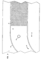
- Fig. 9 is a top plan view of a block of the plate of Figs. 7-7A;
- Fig. 9A is a front elevational view of the block of Fig. 9;
- Fig. 9B is a bottom plan view of the block of Figs. 9-9A;
- Fig. 10 is a Fig. 4 is a schematic top plan view of a laning structure in accordance with another embodiment; and
- Fig. 11 is a section taken along line 11-11 in Fig. 10.
- One embodiment of an assembly for handling and packaging dosage forms is depicted in Figs. 1-9. An
infeed structure 22, alaning structure 35 and aplenum structure 32 extending between the infeed structure and the laning structure arrange dosage forms such as tablets into rows so that they can be arranged into packages. The dosage forms handled by the assembly may be any type of dosage form, including tablets, capsules, pills, pellets, and other forms. The assembly is particularly useful for fragile dosage forms. - The tablets are transported throughout the assembly on a movable surface or conveyance device, such as a conventional conveyor belt. A rotating drum or disk may also be used. The conveyor belt is driven by any
conventional means 13 such as an electric motor or other conventional drive so that theupper run 10 of the belt moves in adownstream direction 11. The motor is controlled by a switch and a control device for starting and stopping the conveyor belt and varying the speed of the conveyor belt. The conveyor belt is adjacent atablet press 12 which formstablets 15. The tablets travel from the tablet press down aramp 21 to the conveyor belt. The ramps, as well as the other surfaces used in the assembly which contact the tablets, are preferably made of a smooth material which will not interfere with the sliding of the tablets to the next stage of the system. Many plastics and other materials may be used. Alternatively, the ramps and other surfaces may be coated with a smooth material such as a fluoropolymer of the type sold under the trademark TEFLON to promote the sliding of the tablets. - The
upper run 10 of the belt receivestablets 15 from thetablet press 12 and conveys the tablets in thedownstream direction 11. Theinfeed structure 22 includes aguide wall structure 14 is disposed over theupper run 10 of the conveyor belt, and guides the tablets as they move downstream with the belt. The speed of the conveyor belt is variable in a range from about 0.2 to 0.5 m/s (40 to 100 feet per minute). Theguide wall structure 14 defines achannel 20 over theupper run 10 of the belt extending from the tablet press to the laning structure. Thechannel 20 has atop wall 17, afirst side wall 18, asecond sidewall 19 and an open bottom 16, as shown in Fig. 5. Theopen bottom 16 of thechannel 20 faces toward theupper run 10 of the conveyor belt, so thattablets 15 disposed on the belt are moved downstream within thechannel 20 and are guided by thetop wall 17,first sidewall 18, andsecond sidewall 19. - As depicted in Fig. 2, the
guide wall structure 14 includes aguide portion 25, having anentry 26 adjacent thetablet press 12 and anexit 27 adjacent aplenum structure 32. The guide wall structure also defines theplenum structure 32, having aplenum entry 28 adjacent theexit 27 and atransitional portion 33, as depicted in Figs. 2-4. The transitional portion guides tablets into the laning structure which is typically wider than theguide portion 25, which causes tablets to back up to the juncture between the guide portion and transitional portion. Thus, theguide portion 25 includes acurved portion 45 of theguide wall structure 14 provided for guiding the tablets into the widertransitional portion 33 of theplenum structure 32. Thetransitional portion 33 is adjacent aninlet end 34 of thelaning structure 35. Thelaning structure 35 has afirst side 46 and asecond side 47 and includes a series offinger members 36. Thefinger members 36 extend in adownstream direction 11 from theinlet end 34 of the laning structure to adownstream end 38 of thelaning structure 35. Thefinger members 36 definelanes 40 which are spaced from each other in alateral direction 43 transverse to thedownstream direction 11. The lanes arrange the tablets intorows 42. - Although tablets of almost any size can be packaged in the apparatus, the dimensions of the guide wall structure depends upon the size of the tablet or other dosage form. The embodiment shown in Figs. 1-9 is designed to handle tablets having a 6.4 mm (1/4") diameter, but the dimensions provided below may be varied for tablets having a 17.5 mm (11/16)", 12.7 mm (1/2"), or 15.9 mm (5/8") diameter, or other sizes and types of dosage forms. The thickness of the tablets range from about 2.5 mm (0.100") to 8.1 mm (0.320"). Although the dimensions of the
guide wall structure 14 vary with the size of the dosage form handled in the system, thechannel 20 in the embodiment of Figs. 1-9 has a width of 149 mm (5-7/8") at the section shown in Fig. 5 and a length of 1010 mm (39-3/4") and the height of the channel is equal to the tablet thickness plus 1 mm (0.040"). Thecurved portion 45 has the same width as thechannel 20 and is defined by theguide wall structure 14. Thetransition portion 33 in the embodiment of Fig. 4 has a width of 378 mm (14-7/8"). The width of the transitional portion is the dimension transverse to thedownstream direction 11. - The
lanes 40 depicted in Fig. 4, extend in thedownstream direction 11 and are spaced apart from one another in thelateral direction 43. Thefinger members 36 of thelaning structure 35 preferably comprise vibratingguide members 36 which assist in moving the tablets downstream. The lanes for the 6.4 mm (1/4") tablets are 15.9 mm (5/8") wide and 308 mm (12-1/8") long. The vibrating members are attached to a selectively operable actuator oractuators 78 such as a solenoid, electric motor operated actuator, hydraulic cylinder or, most preferably, an air cylinder for vibrating theguide members 36. The vibrating members agitate the tablets so that they move downstream within the lanes to thedownstream end 38. In preferred embodiments, the vibrating members which define the lanes are preferably formed with an aperture separating two side bars, so that each bar can be replaced in the event that they become warped or otherwise damaged. - A
dump gate 80 is positioned at thedownstream end 38 of thelaning structure 35. Adjacent thedownstream end 38 is atablet pickup area 82 of thelanes 40. Adjacent the dump gate on a side of the dump gate opposite thepickup area 82, is a discardramp 81. In the closed position illustrated in Fig. 4, the dump gate blocks thedownstream end 38 of eachlane 40. The downstream motion of the conveyor belt beneath the laning structure carries tablets downstream until the leading or most downstream tablet in each lane stops against the closed dump gate. In certain embodiments, the laning structure includes a surface beneath the lanes which is sloped in thedownstream direction 11 to encourage tablets and other debris to move toward thedownstream end 38 of thelaning structure 35. - A
form handling device 38 is disposed above thepickup area 82 of thelanes 40. In preferred embodiments, theform handling device 38 comprises a robotic handler including an array of finger-like channels 64, a softrubber suction cup 65 on eachsuch finger 64, and a vacuum pump connected to the finger-like channels 64 for applying suction through the suction cups so that the suction cups can receive and lift thetablets 15. Therobotic handler 83 receives the tablets and transports them to the packaging machine, where the tablets are released by releasing the vacuum. In other embodiments, other "pick and place" form handlers are used to transport tablets frompickup area 82 to the packaging machine. - The array of finger-
like channels 64 preferably comprises a two-dimensional array of thechannels 64, arranged in a carriage assembly connected to anarm 66 rotatable around a vertical axis. Asuction cup 65 of eachchannel 64 corresponds to a tablet arranged in thepickup area 82 of the lanes, as depicted in Fig. 4A. After lifting the tablets, thearm 66 of the robotic hander carries the tablets to the packaging machine. - The dump gate is attached to a selectively
operable actuator 79 such as a solenoid, electric motor operated actuator, hydraulic cylinder or, most preferably, an air cylinder for opening and closing the dump gate. A number of air cylinder models may be used and the type of air cylinder depends upon the size tablet being packaged. The actuator is linked to a control device such as a mechanical, fluidic, electronic or electromechanical controller of known type which is also linked to the robotic handler. In preferred embodiments, the controller is a programmable, computer actuated controller having functions controlled by software. - In preferred embodiments, a detection system with three (3) sensors spaced along the
infeed structure 22 is provided for detecting a backup of tablets in theguide wall structure 14. Thefirst sensor 51 is located adjacent theexit 27 of the guide portion proximate to thecurved portion 45, as depicted in Fig. 2. Thefirst sensor 51 provides an indication that thecurved portion 45 is clear and to turn on thetablet press 12 and commence flow of tablets through the packaging system. Thesecond sensor 52 produces an indication that the tablets have backed up from theexit 27 to thesecond sensor 52 and that the tablet press rate should be reduced. Thethird sensor 53, located at theentry 26 of theguide portion 25, produces an indication that the tablets backed up to thethird sensor 53 and to turn off the tablet press. Software and computer hardware may be provided to receive the indications from the sensors and to control the operation of the tablet press. - Where the tablets handled by the system are of the soft, fragile type discussed above, dust is generated within the
channel 20 from thetablets 15 moving therein. Thus, preferred embodiments include aguide wall structure 14 having vacuum holes 50 for dedusting thechannel 20. A vacuum is preferably attached to thetop wall 17 of theguide wall structure 14 for this purpose. Theguide wall structure 14 is preferably formed from a plastic material which is also preferably transparent for visual observation of the tablets transported within the system. - In operation, tablets are carried in the
downstream direction 11 on theupper run 10 of the conveyor belt, through theguide wall structure 14. The tablets are guided through thecurved portion 45 to theplenum structure 32 and travel through thetransitional portion 33. In thetransitional portion 33, the tablets generally travel from thefirst side 46 in thelateral direction 43 toward thesecond side 47 of thelaning structure 35 before entering thelanes 40. Upon entering the lanes, the tablets travel in thedownstream direction 11. - With the
dump gate 80 closed, arow 42 of tablets stack up in upstream-to-downstream order within thetablet pickup area 82 of eachlane 40. Theform handling device 83, engages thetablets 15 stacked within thevarious lanes 40 and lifts a predetermined number of tablets out of each lane during each cycle of operation. The operation of the embodiment having the robotic tablet handler will now be described. As depicted in Fig. 4A, the robotic tablet handler descends from a first position 83A to asecond position 83b to receive the tablets within thelanes 40. For ease of illustration, only a few of thelanes 40 depicted in Fig. 4 are depicted in Fig. 4A. The vacuum is applied and the tablets are received within thesuction cups 65. Thearm 66 raises the array of finger-like channels 64 andsuction cups 65 to position 83a and rotates 180° to position 83C, over thepackaging machine 90. In thepickup area 82 of thelanes 40, thetablet 15b immediately after thelast tablet 15a lifted by therobotic handler 83 then becomes the leading tablet of the next group to be received be therobotic tablet hander 83. - During each cycle of the robotic handler, the controller operates the actuator in synchronism with the
handler 83 or other form handling device so that thedump gate 80 opens after thehandler 83 has engaged a group of tablets and remains open for a preselected open time after thehandler 83 has lifted that group of tablets out of thelaning structure 35. While the dump gate is open, debris accumulated in each lane moves downstream, past thedump gate 80 and down the discardramp 81, where debris is collected for disposal. The next group of tablets move downstream to thedownstream end 38. The open time of thedump gate 80 is selected so that it is just slightly less than the time required for the leading tablet of the next group to reach thedownstream end 38 of thelane 40. Thus, thedump gate 80 returns to the closed position just before the leading tablet (for example,tablet 15b) of the next group arrives at thedump gate 80. This cycle of operations is repeated. - The dump date may be manually operated in some embodiments, which is less preferred. Attempts have been made heretofore to use a dump gate which is manually actuated by an operator in response to visible accumulation of debris in the lanes, or which is actuated at some lengthy intervals. Where the dump gate is manually operated, debris such as tablets or parts of tablets missed by the robotic tablet handler interfere with the next set of tablets preceding to the
pickup area 82 through thelanes 40. Breakage of tablets occurs in the laning area before a human operator is alerted who can operate the dump gate. Also, when the manually operated dump gate is held open, some good tablets pass out of the dump gate and are wasted. By contrast, in the preferred systems according to this aspect of the invention, debris is cleared during each cycle of the handler, without wasting good tablets. - Other embodiments of the invention include an infeed structure, a plenum structure and a laning structure adapted to different sized tablets and different types of dosage forms. Certain preferred embodiments also include a
member 60, preferably having a triangular shape, at the juncture of theguide portion 25 and theplenum structure 32. Thetriangle 60 alleviates jamming of the tablets at this juncture. It has been found that thistriangular member 60 is not required for 6.4 mm (1/4") tablets in the embodiment of Figs. 1-9, but is preferred for larger tablets. For example, in packaging 12.7 mm (1/2") tablets, a stationary triangular member is preferably used to alleviate jamming. For 15.9 mm (5/8") tablets, a triangular member which is spring-loaded is preferably used. The triangular member, depicted in Figs. 10 and 11, has afirst leg 61 and asecond leg 62 facing upstream and athird leg 63 facing downstream, facing thelaning structure 35. The spring-loadedtriangular member 60 is moveable from side to side intraverse directions downstream direction 11. The triangle is biased in a central position 70 by a biasing means 73, including a spring or other conventional biasing devices. The tablets bounce off the triangle, which alleviates jamming of the tablets in theplenum entry 28. Tablets entering the plenum entry may slide along thefirst leg 61 andsecond leg 62 and proceed to thetransitional portion 33. However, in the event thattablets 15 begin to jam up, the tablets apply a small force upon the triangular member, which compresses the biasing device orspring 73. As shown in Fig. 11, the triangle may be moved to one side or the other to offset positions 70a or 70b. The spring reacts, relieving the force of the tablets. The compressibility of the spring must be such that the tablets are not broken. - A packaging device for sealing the tablets into
packages 110 is depicted in Figs. 7-9. After the tablets are sealed into packages, the packages are cut into separate cards which are arranged into boxes. Thepackaging device 90 includes a sealing machine 91 for forming packaged dosage forms. The packages are comprised of first and second sheets of packaging material, preferably foil laminate, which are sealed together in the sealing machine. An example of this type of packaging machine is a Clockner blister-forming machine. Model No. CP11.4 may be used.Blisters 111, which are essentially cup-shaped depressions in the packaging material, have been provided in at least one of the sheets for holding the tablets. In the finished package, which is depicted in Fig. 6, each tablet occupies a pocket formed by theblisters 111. For example, where the product is a relatively fragile tablet, blister packages of the type described concerning certain embodiments of copending, commonly assignedUnited States patent application Serial No. 09/053,298, filed April 1, 1998 , may be used. - The
packaging device 90 is generally of the type known as a "form, fill and seal" machine. The machine forms a web of a packaging material into blisters, whereupon theform handler 83 places the tablets in the blisters. In embodiments having a robotic tablet handler, eachsuction cup 65 of the robotic handler corresponds to ablister 111 in the packaging material, as depicted in Fig. 4A. The robotic handler received tablets at thepickup area 82 and rotates 180° from position 83C to position 83D, toward thepackaging material 112 onsupport 114. After thearm 66 lowers to the packaging material, the tablets are release intoblisters 111. The packaging material advances along a conveyor belt, series of rollers or asimilar conveyance device 68 to a sealing machine through a series of checking systems which ensure that the first sheet is free from displaced tablets and debris prior to reaching the sealing machine. At the sealing machine, the packaging material is sealed to a web or sheet of lid stock so that the lid stock closes the blisters and holds the tablets in the blisters. - The sealing machine includes a top and bottom plate. The top and bottom plates of the sealing machine each have sealing faces, for engaging the lid stock and packaging material, respectively. In the embodiment depicted in Fig. 7, blister cavities 115 are provided in the sealing
face 116 of thebottom plate 113. Depending upon the type of package formed, the top plate may include blister cavities, as well. - The plates preferably have
registration markers 17 so that the top and bottom plates can be properly aligned. At least one of the plates, typically the top plate, is heated so that a heat-activated material in the packaging material or lid stock seals the tablet package when the top and bottom plates are brought into engagement. Most preferably, the bottom plate is also heated. The heaters are connected to controllers for controlling the heating of the plates in the conventional manner. - After receiving tablets from
form handling device 83, the web of the packaging material is transferred fromsupport 114 to the sealingface 116 of thebottom plate 113 so that theblisters 111 rest in the blister cavities 115 of thebottom plate 113. The lid stock is placed on the packaging material, overlying the tablets in the blisters and the sealing machine urges the top plate and bottom plate together, so that these plates engage the package material and lid stock therebetween. The top and bottom plates are brought together to seal the packaging material. As is well known in the blister packaging art, sealing occurs according to three (3) parameters: heat, pressure and time. - In preferred embodiments, at least the bottom plate is designed with recessed regions 120 depicted in Fig. 7. The recessed regions apply no pressure to the blister pack material and the sealing
face 116 comprises relatively raised regions where the seal is to be formed. This feature focuses the force and heat of the sealing device on the portions of the blister pack where sealing is desired. After a pre-determined sealing time is reached, the plates are disengaged and the sealedblister pack 110 is transported to a blister pack card punch and thereafter to a cartoner for arrangement in boxes. Fig. 6 depicts a blister package for 12.7 mm (1/2") tablets. - In preferred embodiments, at least one of the top and bottom plates is designed to evenly distribute the force and heat of the sealing machine along the sealing faces of the plates. The present invention addresses this problem by providing, rather than one
continuous bottom plate 113, a plate comprised of a plurality ofblocks 122 which can move with respect to one another over a range of motion. In the particular embodiment illustrated in Fig. 7, four (4)movable blocks 122, are provided. Eachblock 122, depicted in Fig. 9, has arear face 123 opposite the sealingface 116 and acircular depression 125 in the rear face. Each block also has a compartment cut out for heaters which communicate with controls for heating the plate, as discussed above. Theblocks 122 are formed from metals such as steel, aluminum or the like which are selected according to conventional criteria such as wear resistance and good heat transfer. Eachblock 122 rests on a ball-like member 126, depicted in Fig. 8, which is attached to a base 128 so that theball 126 is engaged by thecircular depression 125 and eachblock 122 is floatably supported by thebase 128. The spacing of theblocks 122 on the base accommodates individual tilting of each block with respect to the horizontal plane. Thus, eachblock 122 is free to tilt around any horizontal axis. This design has the benefit of achieving better sealing in the tablet packages. When the top plate descends and engages the blister pack material, lid stock and bottom plate, the various blocks constituting thebottom plate 122 tilt and adjust to achieve an evenly distributed pressure over the blister pack material. After a predetermined sealing time, the plates are released from thepackage 110, which proceeds to the cartoner. - In other embodiments, more or fewer blocks can be employed. In addition, the tilting movement can be provided by other arrangements, such as a dual-gimbal mount, wherein each block is pivotally mounted to a gimbal frame for tilting movement around a first horizontal axis, and the gimbal frame is pivotally mounted to the base for tilting movement around a second horizontal axis perpendicular to the first horizontal axis. Alternatively, each block can be mounted to the base by a pad of a resilient material such as a high-temperature silicone rubber, or by a set of springs, so that each block is free to move relative to the base in a limited range of tilting movement. In the embodiment shown, the bottom plate has individual blocks, whereas the top plate is a unitary, solid part. However, the reverse arrangement, with a solid bottom plate and a top plate composed of movable parts, can also be employed. In a further alternative, both plates can be formed with movable parts.
- An assembly for handling and packaging pharmaceutical dosage forms may include:
- (a) an infeed structure for accepting a series of dosage forms including a surface movable in a downstream direction in a downstream direction, a laning structure defining a plurality of lanes extending in said downstream direction and having a downstream end, and a plenum structure extending from said infeed structure to said laning structure including a guide portion for guiding dosage forms carried by said surface into said laning structure;
- (b) a form handling device for receiving dosage forms and transporting dosage forms from said laning structure to a packaging device;
- (c) a dump gate having a closed position wherein said dump gate blocks said lanes at said downstream ends thereof, whereby dosage forms will accumulate in said lanes when said dump gate is in said closed position and an open position in which said dump gate does not block the lanes; and
- (d) a timed controller for opening said dump gate after said handling device receives dosage forms whereby debris will be carried downstream out of said laning structure after said form handling device receives dosage forms from said laning structure.
- According to a further embodiment of the assembly, said timed controller further comprises a computer communicating with said form handling device and said dump gate.
- According to a further embodiment, the assembly may comprise a guide wall structure defining said guide portion and including a curved portion.
- According to a further embodiment of the assembly, said guide wall structure also defines said plenum structure, said plenum structure including a plenum entry and said guide wall structure being shaped to guide dosage forms so that dosage forms enter said plenum structure at said plenum entry adjacent a first side of said laning structure and travel in a lateral direction transverse to said downstream direction toward a second side of said laning structure before entering said lanes.
- According to a further embodiment of the assembly, said curved portion includes a member adjacent said plenum entry for relieving jamming of dosage forms.
- According to a further embodiment of the assembly, said member comprises a movable member and further comprising a biasing means for vibrating said movable member to agitate dosage forms.
- According to a further embodiment of the assembly, said laning structure includes a surface for supporting dosage forms, said surface sloping in said downstream direction to said dump gate so that debris is carried out of said laning structure by said surface when the dump gate is in the open position.
- According to a further embodiment, the packaging device may comprise a top plate and a bottom plate for engaging a packaging material and a lid stock therebetween to seal said packaging material and said lid stock to one another, wherein at least one of said top plate and said bottom plate is comprised of a plurality of blocks and a base for supporting said plurality of blocks thereon, said blocks being floatably supported by said base and individually movable with respect to the base, for evenly distributing pressure applied to said package material and said lid stock by said top and bottom plates.
- According to a further embodiment of the device, each of said blocks has a first surface on which said packaging material is engaged, and wherein each of said blocks is free to tilt relative to said base in all directions.
- According to a further embodiment of the device, said base includes a ball-like member for each said block, each said block including a circular cavity formed thereon at a second surface of each said block opposite said first surface for receiving said ball-like member.
- According to a further embodiment of the device, at least one of said top plate and said bottom plate is heated for sealing said packaging material and said lid stock together.
- As will be readily appreciated, numerous other variations and combinations of the features discussed above will be employed without departing from the present invention. Accordingly, the foregoing description of preferred embodiments should be taken by way of illustration, rather than by way of limitation, of the features discussed above. Other desirable features and functions served by preferred aspects of the invention are set forth in the accompanying drawings and claims.
- The present invention can be applied in the packaging of pharmaceuticals.
Claims (6)
- An assembly for guiding pharmaceutical dosage forms in a packaging assembly, comprising:(a) a surface (10) movable in a downstream direction (11);(b) a laning structure (35) extending in a lateral direction transverse to said downstream direction (11) and defining a plurality of laterally-spaced lanes (40) extending in said downstream direction (11); and characterized by(c) guide wall structures (14) including a curved portion (45) and a wall structure defining a plenum structure (32) upstream of said laning structure (35), said curved portion (45) guiding dosage forms carried by said surface (10) so that dosage forms enter said plenum structure (32) at a plenum entry adjacent a first side (46) of said laning structure (35) and travel laterally toward a second side (47) of said laning structure (35) before entering said lanes (40).
- The assembly of claim 1, comprising a form handling device (38) for receiving dosage forms and transporting dosage forms from said laning structure (35) to a packaging device (90).
- The assembly of claim 2 wherein said packaging device (90) includes a top plate and a bottom plate (113) for engaging a packaging material and a lid stock therebetween to seal the packaging material and lid stock together, forming packaged dosage forms.
- The assembly of claim 3 wherein at least one of said top plate and said bottom plate (113) includes a plurality of blocks (122) and a base (128) for supporting said plurality of blocks (122), said blocks being floatably supported on the base (128) and individually movable with respect to the base (128).
- The assembly of claim 4 wherein said lanes (40) have a downstream end and the assembly comprises a dump gate (80) at said downstream end having an open position and a closed position.
- The assembly of claim 5, comprising timed controller for opening said dump gate (80) after said handling device (38) receives dosage forms.
Priority Applications (1)
| Application Number | Priority Date | Filing Date | Title |
|---|---|---|---|
| CY20071101475T CY1107443T1 (en) | 1998-03-09 | 2007-11-14 | DEVICE FOR HANDLING AND PACKAGING OF BRAKE DISCS |
Applications Claiming Priority (3)
| Application Number | Priority Date | Filing Date | Title |
|---|---|---|---|
| US7736398P | 1998-03-09 | 1998-03-09 | |
| US77363P | 1998-03-09 | ||
| EP99914893A EP1107911B1 (en) | 1998-03-09 | 1999-03-09 | Apparatus for handling and packaging friable tablets |
Related Parent Applications (1)
| Application Number | Title | Priority Date | Filing Date |
|---|---|---|---|
| EP99914893A Division EP1107911B1 (en) | 1998-03-09 | 1999-03-09 | Apparatus for handling and packaging friable tablets |
Publications (3)
| Publication Number | Publication Date |
|---|---|
| EP1591360A2 EP1591360A2 (en) | 2005-11-02 |
| EP1591360A3 EP1591360A3 (en) | 2006-04-12 |
| EP1591360B1 true EP1591360B1 (en) | 2007-08-22 |
Family
ID=35052535
Family Applications (1)
| Application Number | Title | Priority Date | Filing Date |
|---|---|---|---|
| EP04025128A Expired - Lifetime EP1591360B1 (en) | 1998-03-09 | 1999-03-09 | Apparatus for handling and packaging friable tablets |
Country Status (1)
| Country | Link |
|---|---|
| EP (1) | EP1591360B1 (en) |
Family Cites Families (3)
| Publication number | Priority date | Publication date | Assignee | Title |
|---|---|---|---|---|
| US2544125A (en) * | 1944-12-26 | 1951-03-06 | Joseph C Bain | Packaging machine having article receiving and transferring sections for handling articles in group formation |
| US3490197A (en) * | 1968-04-15 | 1970-01-20 | American Home Prod | Tablet counting and bottling machine |
| DE4406089C2 (en) * | 1994-02-24 | 1996-04-11 | Lingenfelder Oli Spezialanlage | Device for filling tablets or the like into tablet tubes |
-
1999
- 1999-03-09 EP EP04025128A patent/EP1591360B1/en not_active Expired - Lifetime
Also Published As
| Publication number | Publication date |
|---|---|
| EP1591360A2 (en) | 2005-11-02 |
| EP1591360A3 (en) | 2006-04-12 |
Similar Documents
| Publication | Publication Date | Title |
|---|---|---|
| EP1107911B1 (en) | Apparatus for handling and packaging friable tablets | |
| US5607282A (en) | Depalletizing and dispensing apparatus and method | |
| EP1986941B1 (en) | Pick and place handling device and method for its use | |
| US4620826A (en) | Materials handling apparatus | |
| US5060455A (en) | Robotic case packing system and method | |
| US6398008B1 (en) | Aligning and conveying method of packaged article and apparatus thereof | |
| US5765337A (en) | Apparatus and method for stacking and boxing stackable articles | |
| US4259826A (en) | Case packing machine | |
| US20020194815A1 (en) | Apparatus for handling and packaging friable tablets | |
| JP2530208Y2 (en) | Equipment for filling sheet blanks into containers | |
| JPH072229A (en) | Liquid container transport processing device | |
| EP1591360A2 (en) | Apparatus for handling and packaging friable tablets | |
| KR950000538A (en) | Packing material removal device | |
| JPH11513648A (en) | Can lid supply device | |
| JP2001002033A (en) | Distributing device for continuous item packaging bags | |
| GB2435252A (en) | Improved pick and place handling device | |
| JP2022171149A (en) | Conveyance direction shifting device | |
| JPH0672814U (en) | Unpacking machine | |
| KR101974969B1 (en) | a robot bag placer and a control method of the same | |
| KR200144135Y1 (en) | Bag feeder of juice packing machine | |
| JP2000296805A (en) | Lid applying device for container having lid | |
| JPH03147197A (en) | Commodity conveying device for automatic vending machine | |
| JPH0516604U (en) | Roll product boxing machine | |
| AU4053893A (en) | Apparatus and process for packaging articles |
Legal Events
| Date | Code | Title | Description |
|---|---|---|---|
| PUAI | Public reference made under article 153(3) epc to a published international application that has entered the european phase |
Free format text: ORIGINAL CODE: 0009012 |
|
| AC | Divisional application: reference to earlier application |
Ref document number: 1107911 Country of ref document: EP Kind code of ref document: P |
|
| AK | Designated contracting states |
Kind code of ref document: A2 Designated state(s): AT BE CH CY DE DK ES FI FR GB GR IE IT LI LU MC NL PT SE |
|
| PUAL | Search report despatched |
Free format text: ORIGINAL CODE: 0009013 |
|
| AK | Designated contracting states |
Kind code of ref document: A3 Designated state(s): AT BE CH CY DE DK ES FI FR GB GR IE IT LI LU MC NL PT SE |
|
| RIC1 | Information provided on ipc code assigned before grant |
Ipc: B65B 51/14 20060101ALI20060221BHEP Ipc: B65B 7/28 20060101AFI20060221BHEP Ipc: B65B 23/00 20060101ALI20060221BHEP Ipc: B65B 35/30 20060101ALI20060221BHEP Ipc: B65B 5/10 20060101ALI20060221BHEP |
|
| 17P | Request for examination filed |
Effective date: 20061011 |
|
| AKX | Designation fees paid |
Designated state(s): AT BE CH CY DE DK ES FI FR GB GR IE IT LI LU MC NL PT SE |
|
| GRAP | Despatch of communication of intention to grant a patent |
Free format text: ORIGINAL CODE: EPIDOSNIGR1 |
|
| GRAS | Grant fee paid |
Free format text: ORIGINAL CODE: EPIDOSNIGR3 |
|
| GRAA | (expected) grant |
Free format text: ORIGINAL CODE: 0009210 |
|
| AC | Divisional application: reference to earlier application |
Ref document number: 1107911 Country of ref document: EP Kind code of ref document: P |
|
| AK | Designated contracting states |
Kind code of ref document: B1 Designated state(s): AT BE CH CY DE DK ES FI FR GB GR IE IT LI LU MC NL PT SE |
|
| REG | Reference to a national code |
Ref country code: GB Ref legal event code: FG4D |
|
| REG | Reference to a national code |
Ref country code: CH Ref legal event code: EP |
|
| REG | Reference to a national code |
Ref country code: IE Ref legal event code: FG4D |
|
| REG | Reference to a national code |
Ref country code: GR Ref legal event code: EP Ref document number: 20070402666 Country of ref document: GR |
|
| REF | Corresponds to: |
Ref document number: 69936949 Country of ref document: DE Date of ref document: 20071004 Kind code of ref document: P |
|
| REG | Reference to a national code |
Ref country code: PT Ref legal event code: SC4A Free format text: AVAILABILITY OF NATIONAL TRANSLATION Effective date: 20070926 |
|
| REG | Reference to a national code |
Ref country code: CH Ref legal event code: NV Representative=s name: ARNOLD & SIEDSMA AG |
|
| REG | Reference to a national code |
Ref country code: SE Ref legal event code: TRGR |
|
| REG | Reference to a national code |
Ref country code: DK Ref legal event code: T3 |
|
| ET | Fr: translation filed | ||
| REG | Reference to a national code |
Ref country code: ES Ref legal event code: FG2A Ref document number: 2293145 Country of ref document: ES Kind code of ref document: T3 |
|
| PLBE | No opposition filed within time limit |
Free format text: ORIGINAL CODE: 0009261 |
|
| STAA | Information on the status of an ep patent application or granted ep patent |
Free format text: STATUS: NO OPPOSITION FILED WITHIN TIME LIMIT |
|
| 26N | No opposition filed |
Effective date: 20080526 |
|
| PG25 | Lapsed in a contracting state [announced via postgrant information from national office to epo] |
Ref country code: CY Free format text: LAPSE BECAUSE OF NON-PAYMENT OF DUE FEES Effective date: 20080309 |
|
| REG | Reference to a national code |
Ref country code: FR Ref legal event code: PLFP Year of fee payment: 18 |
|
| REG | Reference to a national code |
Ref country code: FR Ref legal event code: PLFP Year of fee payment: 19 |
|
| REG | Reference to a national code |
Ref country code: FR Ref legal event code: PLFP Year of fee payment: 20 |
|
| PGFP | Annual fee paid to national office [announced via postgrant information from national office to epo] |
Ref country code: GB Payment date: 20180321 Year of fee payment: 20 Ref country code: DE Payment date: 20180322 Year of fee payment: 20 Ref country code: CH Payment date: 20180321 Year of fee payment: 20 Ref country code: LU Payment date: 20180321 Year of fee payment: 20 Ref country code: DK Payment date: 20180321 Year of fee payment: 20 Ref country code: NL Payment date: 20180321 Year of fee payment: 20 Ref country code: FI Payment date: 20180322 Year of fee payment: 20 |
|
| PGFP | Annual fee paid to national office [announced via postgrant information from national office to epo] |
Ref country code: GR Payment date: 20180316 Year of fee payment: 20 Ref country code: MC Payment date: 20180314 Year of fee payment: 20 Ref country code: IE Payment date: 20180323 Year of fee payment: 20 Ref country code: BE Payment date: 20180321 Year of fee payment: 20 Ref country code: SE Payment date: 20180321 Year of fee payment: 20 Ref country code: AT Payment date: 20180322 Year of fee payment: 20 Ref country code: FR Payment date: 20180323 Year of fee payment: 20 Ref country code: PT Payment date: 20180305 Year of fee payment: 20 |
|
| PGFP | Annual fee paid to national office [announced via postgrant information from national office to epo] |
Ref country code: ES Payment date: 20180430 Year of fee payment: 20 |
|
| PGFP | Annual fee paid to national office [announced via postgrant information from national office to epo] |
Ref country code: IT Payment date: 20180327 Year of fee payment: 20 |
|
| PGFP | Annual fee paid to national office [announced via postgrant information from national office to epo] |
Ref country code: CY Payment date: 20180308 Year of fee payment: 20 |
|
| REG | Reference to a national code |
Ref country code: DE Ref legal event code: R071 Ref document number: 69936949 Country of ref document: DE |
|
| REG | Reference to a national code |
Ref country code: DK Ref legal event code: EUP Effective date: 20190309 |
|
| REG | Reference to a national code |
Ref country code: NL Ref legal event code: MK Effective date: 20190308 |
|
| REG | Reference to a national code |
Ref country code: CH Ref legal event code: PL |
|
| REG | Reference to a national code |
Ref country code: GB Ref legal event code: PE20 Expiry date: 20190308 |
|
| REG | Reference to a national code |
Ref country code: AT Ref legal event code: MK07 Ref document number: 370889 Country of ref document: AT Kind code of ref document: T Effective date: 20190309 |
|
| REG | Reference to a national code |
Ref country code: IE Ref legal event code: MK9A |
|
| PG25 | Lapsed in a contracting state [announced via postgrant information from national office to epo] |
Ref country code: GB Free format text: LAPSE BECAUSE OF EXPIRATION OF PROTECTION Effective date: 20190308 Ref country code: IE Free format text: LAPSE BECAUSE OF EXPIRATION OF PROTECTION Effective date: 20190309 |
|
| REG | Reference to a national code |
Ref country code: BE Ref legal event code: MK Effective date: 20190309 |
|
| PG25 | Lapsed in a contracting state [announced via postgrant information from national office to epo] |
Ref country code: PT Free format text: LAPSE BECAUSE OF EXPIRATION OF PROTECTION Effective date: 20190410 |
|
| REG | Reference to a national code |
Ref country code: ES Ref legal event code: FD2A Effective date: 20210129 |
|
| PG25 | Lapsed in a contracting state [announced via postgrant information from national office to epo] |
Ref country code: ES Free format text: LAPSE BECAUSE OF EXPIRATION OF PROTECTION Effective date: 20190310 |