EP1590272B1 - Material handling system and method using autonomous mobile drive units and movable inventory trays - Google Patents
Material handling system and method using autonomous mobile drive units and movable inventory trays Download PDFInfo
- Publication number
- EP1590272B1 EP1590272B1 EP04702195A EP04702195A EP1590272B1 EP 1590272 B1 EP1590272 B1 EP 1590272B1 EP 04702195 A EP04702195 A EP 04702195A EP 04702195 A EP04702195 A EP 04702195A EP 1590272 B1 EP1590272 B1 EP 1590272B1
- Authority
- EP
- European Patent Office
- Prior art keywords
- inventory
- mip
- mdu
- station
- mdus
- Prior art date
- Legal status (The legal status is an assumption and is not a legal conclusion. Google has not performed a legal analysis and makes no representation as to the accuracy of the status listed.)
- Expired - Lifetime
Links
- 239000000463 material Substances 0.000 title claims abstract description 18
- 238000000034 method Methods 0.000 title claims description 41
- 230000007246 mechanism Effects 0.000 claims abstract description 11
- 238000003032 molecular docking Methods 0.000 claims abstract description 11
- 238000003860 storage Methods 0.000 claims description 42
- 238000004891 communication Methods 0.000 claims description 27
- 230000008569 process Effects 0.000 claims description 17
- 230000033001 locomotion Effects 0.000 claims description 11
- 230000000694 effects Effects 0.000 claims description 2
- 238000005516 engineering process Methods 0.000 description 9
- 230000032258 transport Effects 0.000 description 7
- 238000009826 distribution Methods 0.000 description 5
- 230000004044 response Effects 0.000 description 5
- 235000008429 bread Nutrition 0.000 description 4
- 238000010586 diagram Methods 0.000 description 4
- 238000004519 manufacturing process Methods 0.000 description 3
- 230000001413 cellular effect Effects 0.000 description 2
- 230000008859 change Effects 0.000 description 2
- 230000006870 function Effects 0.000 description 2
- 235000013336 milk Nutrition 0.000 description 2
- 239000008267 milk Substances 0.000 description 2
- 210000004080 milk Anatomy 0.000 description 2
- 230000008520 organization Effects 0.000 description 2
- 238000005096 rolling process Methods 0.000 description 2
- 230000026676 system process Effects 0.000 description 2
- 230000003044 adaptive effect Effects 0.000 description 1
- 230000006399 behavior Effects 0.000 description 1
- 238000005452 bending Methods 0.000 description 1
- 238000004364 calculation method Methods 0.000 description 1
- 238000013461 design Methods 0.000 description 1
- 238000011161 development Methods 0.000 description 1
- 230000018109 developmental process Effects 0.000 description 1
- 238000005108 dry cleaning Methods 0.000 description 1
- 238000005429 filling process Methods 0.000 description 1
- 235000013305 food Nutrition 0.000 description 1
- 238000009434 installation Methods 0.000 description 1
- 230000010354 integration Effects 0.000 description 1
- 230000004807 localization Effects 0.000 description 1
- 238000013507 mapping Methods 0.000 description 1
- 238000005007 materials handling Methods 0.000 description 1
- 230000005055 memory storage Effects 0.000 description 1
- 230000003340 mental effect Effects 0.000 description 1
- 238000010295 mobile communication Methods 0.000 description 1
- 230000006855 networking Effects 0.000 description 1
- 230000003287 optical effect Effects 0.000 description 1
- 238000005192 partition Methods 0.000 description 1
- 238000012545 processing Methods 0.000 description 1
- 230000011664 signaling Effects 0.000 description 1
- 241000894007 species Species 0.000 description 1
- 238000009987 spinning Methods 0.000 description 1
- 238000011079 streamline operation Methods 0.000 description 1
- 229940034610 toothpaste Drugs 0.000 description 1
- 239000000606 toothpaste Substances 0.000 description 1
- 238000012546 transfer Methods 0.000 description 1
- 230000000007 visual effect Effects 0.000 description 1
- 230000003245 working effect Effects 0.000 description 1
Images


Classifications
-
- G—PHYSICS
- G05—CONTROLLING; REGULATING
- G05D—SYSTEMS FOR CONTROLLING OR REGULATING NON-ELECTRIC VARIABLES
- G05D1/00—Control of position, course or altitude of land, water, air, or space vehicles, e.g. automatic pilot
- G05D1/02—Control of position or course in two dimensions
- G05D1/021—Control of position or course in two dimensions specially adapted to land vehicles
- G05D1/0268—Control of position or course in two dimensions specially adapted to land vehicles using internal positioning means
- G05D1/0274—Control of position or course in two dimensions specially adapted to land vehicles using internal positioning means using mapping information stored in a memory device
-
- G—PHYSICS
- G05—CONTROLLING; REGULATING
- G05D—SYSTEMS FOR CONTROLLING OR REGULATING NON-ELECTRIC VARIABLES
- G05D1/00—Control of position, course or altitude of land, water, air, or space vehicles, e.g. automatic pilot
- G05D1/02—Control of position or course in two dimensions
- G05D1/021—Control of position or course in two dimensions specially adapted to land vehicles
- G05D1/0276—Control of position or course in two dimensions specially adapted to land vehicles using signals provided by a source external to the vehicle
- G05D1/0278—Control of position or course in two dimensions specially adapted to land vehicles using signals provided by a source external to the vehicle using satellite positioning signals, e.g. GPS
-
- G—PHYSICS
- G05—CONTROLLING; REGULATING
- G05D—SYSTEMS FOR CONTROLLING OR REGULATING NON-ELECTRIC VARIABLES
- G05D1/00—Control of position, course or altitude of land, water, air, or space vehicles, e.g. automatic pilot
- G05D1/02—Control of position or course in two dimensions
- G05D1/021—Control of position or course in two dimensions specially adapted to land vehicles
- G05D1/0287—Control of position or course in two dimensions specially adapted to land vehicles involving a plurality of land vehicles, e.g. fleet or convoy travelling
- G05D1/0291—Fleet control
- G05D1/0297—Fleet control by controlling means in a control room
-
- G—PHYSICS
- G05—CONTROLLING; REGULATING
- G05D—SYSTEMS FOR CONTROLLING OR REGULATING NON-ELECTRIC VARIABLES
- G05D1/00—Control of position, course or altitude of land, water, air, or space vehicles, e.g. automatic pilot
- G05D1/02—Control of position or course in two dimensions
- G05D1/021—Control of position or course in two dimensions specially adapted to land vehicles
- G05D1/0227—Control of position or course in two dimensions specially adapted to land vehicles using mechanical sensing means, e.g. for sensing treated area
-
- G—PHYSICS
- G05—CONTROLLING; REGULATING
- G05D—SYSTEMS FOR CONTROLLING OR REGULATING NON-ELECTRIC VARIABLES
- G05D1/00—Control of position, course or altitude of land, water, air, or space vehicles, e.g. automatic pilot
- G05D1/02—Control of position or course in two dimensions
- G05D1/021—Control of position or course in two dimensions specially adapted to land vehicles
- G05D1/0231—Control of position or course in two dimensions specially adapted to land vehicles using optical position detecting means
- G05D1/0238—Control of position or course in two dimensions specially adapted to land vehicles using optical position detecting means using obstacle or wall sensors
- G05D1/024—Control of position or course in two dimensions specially adapted to land vehicles using optical position detecting means using obstacle or wall sensors in combination with a laser
-
- G—PHYSICS
- G05—CONTROLLING; REGULATING
- G05D—SYSTEMS FOR CONTROLLING OR REGULATING NON-ELECTRIC VARIABLES
- G05D1/00—Control of position, course or altitude of land, water, air, or space vehicles, e.g. automatic pilot
- G05D1/02—Control of position or course in two dimensions
- G05D1/021—Control of position or course in two dimensions specially adapted to land vehicles
- G05D1/0231—Control of position or course in two dimensions specially adapted to land vehicles using optical position detecting means
- G05D1/0242—Control of position or course in two dimensions specially adapted to land vehicles using optical position detecting means using non-visible light signals, e.g. IR or UV signals
-
- G—PHYSICS
- G05—CONTROLLING; REGULATING
- G05D—SYSTEMS FOR CONTROLLING OR REGULATING NON-ELECTRIC VARIABLES
- G05D1/00—Control of position, course or altitude of land, water, air, or space vehicles, e.g. automatic pilot
- G05D1/02—Control of position or course in two dimensions
- G05D1/021—Control of position or course in two dimensions specially adapted to land vehicles
- G05D1/0255—Control of position or course in two dimensions specially adapted to land vehicles using acoustic signals, e.g. ultra-sonic singals
-
- G—PHYSICS
- G05—CONTROLLING; REGULATING
- G05D—SYSTEMS FOR CONTROLLING OR REGULATING NON-ELECTRIC VARIABLES
- G05D1/00—Control of position, course or altitude of land, water, air, or space vehicles, e.g. automatic pilot
- G05D1/02—Control of position or course in two dimensions
- G05D1/021—Control of position or course in two dimensions specially adapted to land vehicles
- G05D1/0257—Control of position or course in two dimensions specially adapted to land vehicles using a radar
-
- G—PHYSICS
- G05—CONTROLLING; REGULATING
- G05D—SYSTEMS FOR CONTROLLING OR REGULATING NON-ELECTRIC VARIABLES
- G05D1/00—Control of position, course or altitude of land, water, air, or space vehicles, e.g. automatic pilot
- G05D1/02—Control of position or course in two dimensions
- G05D1/021—Control of position or course in two dimensions specially adapted to land vehicles
- G05D1/0259—Control of position or course in two dimensions specially adapted to land vehicles using magnetic or electromagnetic means
-
- G—PHYSICS
- G05—CONTROLLING; REGULATING
- G05D—SYSTEMS FOR CONTROLLING OR REGULATING NON-ELECTRIC VARIABLES
- G05D1/00—Control of position, course or altitude of land, water, air, or space vehicles, e.g. automatic pilot
- G05D1/02—Control of position or course in two dimensions
- G05D1/021—Control of position or course in two dimensions specially adapted to land vehicles
- G05D1/0268—Control of position or course in two dimensions specially adapted to land vehicles using internal positioning means
- G05D1/027—Control of position or course in two dimensions specially adapted to land vehicles using internal positioning means comprising intertial navigation means, e.g. azimuth detector
Abstract
Description
- The present invention relates generally to the field of material handling; more particularly, to systems and methods of material handling using autonomous mobile drive units and movable inventory trays.
- The order fulfillment step in the distribution system process is often one of the largest cost components in moving inventory from production to end consumer. This is due to the fact that final order assembly is typically labor intensive and time consuming as operators move among inventory locations and manually handle items. The order fulfillment step involves selecting multiple individual inventory items from among a large assortment of possible items. In contrast, the steps prior to the order fulfillment step in the distribution system process are generally more efficient since they handle inventory in bulk operations such as moving a truckload at a time, a full pallet of one product, or even whole cases.
- Due to its large labor costs, order fulfillment operations have long been the focus of innovations designed to reduce labor. These developments have taken the form of pick-to-light technology, wireless barcode readers, conveyor systems that move orders to operators and even automated storage and retrieval systems ("ASRS") that bring the inventory to the worker. Common ASRS solutions are sometimes called carousels or stockers. A typical carousel may have several thousand storage bins installed in a rotating structure that operates similar to the spinning clothes rack at a dry cleaning facility. Another type of solution known as a sorter is used in conjunction with inventory storage equipment and comprises a revolving tray mechanism that helps sort items coming from inventory into their target order bins. Yet another solution is to provide fixed racking aisles served by a gantry robot that moves in and out of the aisles to bring inventory to the front of the storage system.
- These solutions have been embraced by the distribution industry for their ability to streamline operations and cut operating costs. Yet even with these often expensive systems, fulfillment costs remain high and distribution system managers continue to search for ways to reduce operating costs.
- Another major shortcoming of the current set of order fulfillment solutions is complexity. These automated systems often involve complex control software, lengthy installation, integration and bring-up time, and fail to perform robustly over long periods. Current solutions must be monitored, tuned, and managed by expects with sophisticated knowledge of the system's workings. In addition, these systems are often inflexible to new processes that may be required as an organization's needs change.
- What is needed is an order fulfillment system that is simple to install, operate, and maintain, and that would further reduce operating costs.
-
EP 1 251 083 discloses an automated system for handling palletized merchandise. The system makes it possible to fully automate handling operations of palletized merchandise in factories and distribution centers. -
US 4 669 047 discloses an automated parts supply system for an manufacturing operation to deliver parts to industrial work stations on a "just in time" basis. -
EP 0 458 722 discloses a system and apparatus for handling and moving boxes, containers or the like from one place to another in a factory or a warehouse following instructions from a computer. - According to one aspect of the invention there is provided a system according to claim 1.
- According to another aspect of the invention there is provided a method according to claim 23.
- Acording to a further aspect of the invention there is provided a computer readable medium according to claim 36.
- The present invention will be understood more fully from the detailed description that follows and from the accompanying drawings, which however, should not be taken to limit the invention to the specific embodiments shown, but are for explanation and understanding only.
-
Figure 1 is a top perspective view of a mobile inventory tray -
Figure 2A is a bottom perspective view of a mobile inventory tray -
Figure 2B is a front side view of the mobile inventory tray ofFigure 2A . -
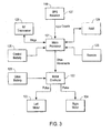
Figure 3 is a high-level system block diagram of tray subsystems -
Figure 4A is a block diagram of a system interface to a warehouse management system -
Figure 4B is a flow chart showing the steps of an order fulfillment process using mobile inventory trays. -
Figure 5 is a top view of mobile inventory trays located on a factory floor -
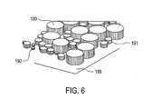
Figure 6 is a perspective view of mobile inventory trays located on a factory floor. -
Figure 7 is a perspective view of mobile inventory trays populating multiple vertical floor levels within a factory space. -
Figure 8 is a perspective view of mobile inventory trays on a factory floor showing openings in the floor enclosure. -
Figure 9A-9C are a side view and first and second perspective views of movable inventory trays and detachable mobile drive units according to one embodiment of the present invention. -
Figure 10 is a top view showing movable inventory trays arranged in a cellular grid with support lanes and queue locations on a factory floor according to one embodiment of the present invention. -
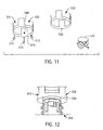
Figure 11 is a three-part movable inventory tray including a base tray, a stack tray, and a mobile drive unit according to one embodiment of the present invention. -
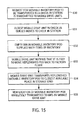
Figure 12 is a mobile drive unit docked to a base tray according to one embodiment of the present invention. -
Figure 13 is a flow chart illustrating a mobile drive unit selection process to fill an order request according to one embodiment of the present invention. -
Figure 14 is a flow chart illustrating an order fill process using autonomous mobile drive units and movable inventory trays according to one embodiment of the present invention. -
Figure 15 is a flow chart illustrating an inventory replenishment process using autonomous mobile drive units and movable inventory trays according to one embodiment of the present invention. - A material handling system and method using mobile autonomous inventory trays and peer-to-peer communications is disclosed. In the following description numerous specific details are set forth, such as the particular configuration of mobile inventory trays, the use of mobile inventory trays on a factory floor, and details regarding communication technologies, etc., in order to provide a thorough understanding of the present invention. However, persons having ordinary skill in the material handling arts will appreciate that these specific details may not be needed to practice the present invention.
- Autonomous mobile inventory trays, which are robotic devices, may be used to extend the concept of bringing a storage location to an operator (e.g., person, robot, etc.). Inventory is stored in mobile trays that can move in any direction under their own power within an established storage area of an organization (e.g., a factory floor). There are no predetermined storage locations for the mobile inventory trays other than that they exist somewhere within a designated space (e.g., an enclosed factory floor). The mobile inventory trays are free to move in any direction necessary including up and down ramps to other inventory floor levels. In this manner, the mobile inventory trays can respond to pick requests and move to pack station locations as part of the pick-and-pack order filling process. The mobile inventory trays may communicate with each other via radio frequency ("RF") technology (e.g., the Bluetooth wireless protocol link) or other types of peer-to-peer communication. The mobile inventory trays may use a pseudolite indoor global positioning system ("GPS") to provide themselves with an accurate position of their location within the predefined inventory storage area. Alternate positioning technologies may also be used such as 802.11-based localization technology or Ultra Wide Band (UWB) signaling based location technology. The mobile inventory trays may then use this information to calculate routes to a pack station, and their peer-to-peer communications ability to coordinate clear paths on the factory floor, or to queue with other trays at control nodes.
- The mobile inventory trays are thus automatic unguided vehicles (an "AUV") rather than automatic guided vehicle (an "AGV"). They are able to navigate the factory floor autonomously using information obtained from the on-board GPS and RF communication systems without any guidance assistance from a remote central computer. This system of mobile inventory trays is self-tuning and self-optimizing. Frequently requested trays migrate closer to the pack stations, while trays containing slower moving inventory items drift back and to the sides and may even move to upper levels. In this sense, the material handling system and method of the present invention is a complex adaptive system and demonstrates emergent system behavior.
- As with all material handling systems, the autonomous storage and retrieval system and method may integrate with existing warehouse management software ("WMS") systems. For example, order requests may be made from a WMS to the material handling system ("MHS") and relayed to the appropriate pack station computers which then direct the order fulfillment from inventory brought to the pack stations utilizing the mobile inventory trays. Orders may be processed in parallel, i.e., multiple orders may be filled simultaneously at a given pack station and multiple pack stations can operate concurrently. Parallel processing of orders allows for real-time fulfillment of orders, in that multiple orders may be filled in minutes rather than in hours. Operators pick the inventory items from the arriving trays, place the items in the order container and, when the order is complete, the pack station computer relays this information to the MHS which in turn notifies the WMS.
- Referring now to
Figure 1 there is shown a perspective view of amobile inventory tray 101.Mobile inventory tray 101 is designed so that it may move autonomously on a surface, such as a factory floor (not shown in this view). Althoughmobile inventory tray 101 may be specifically discussed in reference to its movement on a factory floor, it should be noted thatmobile inventory tray 101 may be used in a variety of capacities including those typified by pick-and-pack operations, order fulfillment operations, or assembly line operations where a few items are drawn from a large population of possible items. An example of such an operation is where a single item is drawn from a large population of books, movies, food supplies, subsystem parts, etc. -
Mobile inventory tray 101 comprises anenclosure 102 to contain various inventory items (not show in this view). InFigure 1 , the enclosure is a circular, one-piece assembly container having a base orbottom wall 103 and aside wall 104 extending upwardly from thebottom wall 103 to create acompartment 105 for the inventory items. It should be noted that the mobile Inventory tray does not necessarily need to be circular, as is shown inFigure 1 . The design of themobile inventory tray 101 may vary in size and shape based on the type of inventory Items the factory stores.Mobile inventory tray 101 also contains ahousing 106 for its drive system and control electronics which will be described in more detail later. - Referring now to
Figure 2A there is shown a bottom perspective view of amobile inventory tray 101. Two drivingwheels base 103 of themobile inventory tray 101. The drivingwheels housing 106 ofmobile inventory tray 101. Thedrive wheels mobile inventory tray 101 in rolling contact with the floor despite imbalances in the items contained inenclosure 102. The motors may be attached to the drivingwheels -
Figure 2B is a front side view of the mobile inventory tray ofFigure 2A . Casters 113 - 115 roll freely and balance themobile inventory tray 101 as it moves along a surface (not shown in this view) by using the drivingwheels mobile inventory tray 101 may use other locomotion means as well, including motor driven track, propellers, ball-wheels or a combination of locomotion devices. -
Figure 3 is a high-level block diagram of the subsystems of a mobile inventory tray. The mobile inventory tray subsystem may be implemented as a computer-based (i.e., microprocessor-based) device. For instance, all of the elements shown inFigure 3 may be contained within housing 106 (seeFig. 1 ) secured to the mobile inventory tray. - A
motor controller 122 controls the movement of the mobile-inventory tray In response to drive movement commands received frommicroprocessor 121.Motor controller 122 is coupled to provide pulse signals to aleft motor 123 and aright motor 124. Themotors Fig. 1 ) which propel the mobile inventory tray forward and backward in response to the signals provided bycontroller 122. Acontrol battery 125 and adrive battery 126 provide the electrical power for operating theelectrical systems 122 and drivemotors -
Microprocessor 121 of the mobileinventory tray subsystem 119 provides the intelligence for the mobile inventory tray. A random-access ("RAM") 129 memory may be included to provide memory storage and as a source of data. A global positioning system ("GPS)receiver 127 , radio frequency ("RF")communication transceiver 128, andsensors 120 provide signals tomicroprocessor 121. For example,GPS receiver 127 outputs position coordinates (x, y, z), whiletransceiver 128 provides command and other messages, andsensors 120 provide signals tomicroprocessor 121. Sensors may include infrared, optical, acoustic, contact, laser, sonar, magnetic, etc. common to mobile robotic vehicles for the purpose of identifying obstacles, avoiding collisions, finding edge limits etc.Microprocessor 121 may also send information (e.g., location, status, diagnostics, etc.) to a remotereceiver utilizing transceiver 128. - As the mobile inventory tray moves about the factory floor it may provide itself with an accurate position of its location at all times using the
GPS receiver 127. TheGPS receiver 127 or equivalent system receives signals for determination of its position coordinates. This position information may include geographic longitude and latitude, as well as the height above normal zero or cartesian coordinates in a manner that is commonly known. Those skilled in the art will appreciate that other guidance methods and systems including radar-based inertial navigation using gyroscopes, laser triangulation, cell-based locator logic (e.g., such as the emergency 911 positioning technology), and visual referencing may also be used by the mobile inventory tray to determine its position coordinates. The mobile inventory tray utilizes the position coordinates obtained from theGPS receiver 127 to calculate routes on the factory floor. It may also utilize position information when navigating to clear paths or queue with other mobile inventory trays, as will be described in detail shortly. - The mobile inventory tray may communicate its position and other data (e.g., the content of its inventory, its destination pack station, etc.) in a peer-to-peer fashion to other mobile inventory trays using RF communication as provided through
receiver 128. In the embodiment illustrated byFigure 3 , a short-range communications medium such as a Bluetooth wireless protocol link or an ordinary infrared communication link may be used to provide a direct wireless link between mobile inventory trays. It should be understood that various wireless and terrestrial communications technologies may be employed. For example, the mobile inventory tray may be equipped with a device for communicating using the Global System for Mobile Communications ("GSM") protocol, the General Packet Radio Service ("GPRS") protocol, the 802.11b Wi-Fi networking protocol, and/or any other communication protocol/standard capable of communicating data. In a two-way mode of operation,transceiver 128 is equipped with an interface for both receiving and transmitting data over the direct wireless link. The wireless link may also communicate with the material handling system ("MHS") (not shown in this view) which interfaces with the individual mobile inventory trays. In this manner, the mobile inventory trays may be directed to various check-in stations and/or pack stations to process orders requested by the MHS. The mobile inventory tray may use the RF communication system provided bytransceiver 128 and the GPS.receiver 127 to navigate to appropriate check-in stations and/or pack stations. - Referring now to
Figure 4A there is shown a block diagram of a system interface to aWMS 130. TheWMS 130 comprises a host computer that communicates data such as a production order (i.e., a request for an item(s) of inventory) to a Materials Handling System ("MHS") 131. TheWMS 130 may be implemented as any one of a number of well known systems used to manage inventory in a factory or warehouse.WMS 130 transmits orders for shipments, tracks receipts, monitors factory inventory, etc. TheWMS 130 transmits the request for the item(s) of inventory to theMHS 131 through a network connection, such as anintranet network 132, It should be noted that a variety of wireless and/or terrestrial communications technologies may also be used to transmit this request, including a wide area network ("WAN"), a local area network ("LAN"), or any other system of interconnections enabling two or more computers to exchange information. TheMHS 131 then transmits the data using the above network connection methods to one or morepack station controllers mobile inventory trays pack station controller RF link 137. - There may be multiple
mobile inventory trays mobile inventory tray mobile inventory trays mobile inventory trays RF link 137. In a matter of seconds (or in a smaller increment of time), everymobile inventory tray Fig. 3 ) to move to thepack station controller mobile inventory trays other control nodes 138 such as charging stations, obstacle markers, ramp markers, etc. using theRF link 137. Whenmobile inventory trays pack station controller mobile inventory trays Pack station controller microprocessor 121 onmobile inventory trays mobile inventory trays mobile inventory trays MHS 131 via theintranet network 132 or via some other wireless and/or terrestrial link, which in turn communicates with the WMS so that it may also track when order requests have been satisfied. - tt should be noted that each
mobile inventory tray station mobile inventory tray mobile inventory tray 135 may carry tubes of toothpaste whilemobile inventory tray 136 may carry cartons of milk. Mobile inventory trays 135,136, etc. known to move themselves to a check-instation Mobile inventory trays MHS 131 to move to check-instation - Another solution provides for giving inventory certain intelligence. According to this solution, as depicted by
Figure 4B , not only can thepack station controller 143 communicate with the inventory, the inventory can also essentially communicate with other inventory via mobile inventory trays.Figure 4B is a flow chart showing the steps of an order fulfillment process using mobile inventory trays interfacing with each other and with the material handling system ofFigure 4A . In one solution, an order (e.g., for bread and milk) is transmitted from theWMS 141 to the MHS. TheMHS 142 then relays this order to a pack station controller. Thepack station controller 143 transmits the order to mobile inventory trays using an RF link. The mobile inventory trays then communicate among themselves to locate the trays that contain the requestedinventory items 144. When a tray does not contain a requested item it relays the request to: peer trays. (e.g., "I do not have bread, but does anyone else have bread?"). The system relays the request all the way across the factory floor in this fashion. In a matter of seconds, every mobile inventory tray that contains requested items begins moving toward thepack station controller 145. As mobile inventory trays containing requested items move toward the pack station, other mobile inventory trays which are not part of this order coordinate to move aside. If two mobile inventory trays attempting to fill the same item request come within a short range of each other (e.g., 30 feet), they may communicate to determine who should fill theorder 146. One mobile inventory tray may state that it has two loaves of bread, and another mobile inventory tray may state that it has five loaves. Then according to embedded tray selection algorithms, one tray moves aside and the other tray continues to move toward the pack station, because it is the optimum mobile inventory tray to fill the order. In this manner, the system is not only self-regulating but also self-optimizing in that item(s) of inventory that are requested more often drift closer to the pack station for more rapid response on subsequent order requests. As mobile inventory trays arrive at pack station, they communicate with each other to form anorderly queue 147 so that an operator can remove the requested items. - Referring now to
Figure 5 there is shown a top view of multiple mobile inventory trays located on a factory floor . According to the solution illustrated byFigure 5 , check-instations pack stations factory floor 170. It should be noted that the configuration of thefactory floor 170 and the location of the check-instations pack stations factory floor 170 may change depending on a variety of considerations (e.g., size and quantity of the inventory item(s) processed, types of inventory item(s), size of the factory floor, etc.).Mobile inventory trays factory floor 170 in any direction using the propulsion means disclosed above (seeFigs. 1 and2 ). Themobile inventory trays stations pack stations mobile inventory trays input areas stations pack stations mobile inventory trays pack stations - Referring now to
Figure 6 there.is shown a perspective view of multiple mobile inventory trays located on a factory floor. Themobile inventory trays Figure 6 , themobile inventory trays Mobile inventory trays mobile inventory trays factory floor 195. This is due to the fact that themobile inventory trays factory floor 195. As described herein, the location of themobile inventory trays - Referring now to
Figure 7 there is shown is a perspective view of mobile inventory trays populating multiple vertical floor levels within a factory space .Mobile inventory trays 201. 202, 203, etc., are located and free to move about on allvertical floor levels inventory storage area 220.Floor enclosure opening 215 andramp access vertical floor level mobile inventory trays floor level 210 or everyfloor level - Referring now to
Figure 8 there is shown a perspective view of mobile inventory trays on a factory floor showing openings in the floor enclosure. In the solution illustrated byFigure 8 ,mobile inventory trays floor enclosure openings Fig. 7 ) for themobile inventory trays mobile inventory trays - There are several different solutions by which mobile autonomous inventory trays can be used to facilitate inventory management, Two such solutions embodiment are described as fixed drive units and detachable drive units. In the detachable drive unit embodiment of the present invention, the drive mechanism is a detachable unit described as a mobile drive unit that can dock and undock with movable inventory trays as needed to carry out inventory movement requests. The movable inventory trays remain motionless until such time as a mobile drive unit docks with a movable inventory tray and moves it through the inventory pictking process and releases it into a storage location. The mobile drive units may place the movable inventory trays down in an organized virtual layout such that other mobile drive units can locate the trays. Movable inventory trays may be stacked to form inventory pods that are moved by the mobile drive units. Another characteristic of the detachable drive unit embodiment is that mobile drive units may send and receive instruction messages in a broadcast fashion over a typical wireless network and may still communicate in a peer-to-peer fashion for such things as collision avoidance.
- In
Figures 1 through 8 herein; the description refers generally to the fixed drive unit embodiment not in accordance with the invention as defined in the claims.Figures 9 through 15 refer generally to the detachable drive unit embodiment in accordance with the invention as defined in the claims. - Referring now to
Figures 9A-9C there is shown a side view and first and second perspective views of movable inventory trays and detachable mobile drive units according to one embodiment of the present invention. The movable inventory trays or "pods" 301, 302. and 303 are designed so that they may be moved about on a factory floor or other type of surface by detachable,mobile drive units mobile drive units base trays movable inventory pods base trays Figures 9A-9C show themobile drive units base - The control units for the
mobile drive units housing 320 secured to themobile drive units Figure 3 herein. As is described in more detail inFigure 3 , the control unit for eachmobile drive unit mobile drive units - The
movable inventory pods casters mobile drive units casters movable inventory pods wheels mobile drive units casters - The
mobile drive units mobile drive units mobile drive units - The
movable inventory pods stackable tray base trays mobile drive units movable inventory pods stackable tray bins partitions bins movable inventory pods mobile drive units - Referring now to
Figure 10 there is shown a top view showing movable inventory pods arranged in a virtual cellular grid with support lanes and queue locations on a factory floor according to one optional embodiment of the present invention. The movable inventory pods 351 may be organized in a virtual grid 360 on thefactory floor 390 so that they may be easily located by the mobile drive units 361. The position of the movable inventory pods 351 on the factory floor, however, are not typically predetermined or fixed by a system computer/controller. Mobile drive units will typically store pods in the closest available storage grid from their current location without regard to any overall inventory layout plan. At other times, the system controller may direct a mobile drive unit to move a pod to a location farther from the pack stations since it does not get called upon frequently for example. The term "virtual" is used to indicate that the grid is only a mathematical construct and that no markings, guides, or fixed hardware is used on the active factory floor area. There may be many more movable inventory pods 351 than mobile drive units 361 located on a given factory floor. For example, there may be 10,000 movable inventory pods on a factory floor and only 2,000 mobile drive units. This configuration achieves a high inventory storage density while using few mobile drive units. Of course, the ratio of movable inventory pods to mobile drive units may vary depending on the configuration and requirements of the operation. - Movable inventory pods 351 dwell in storage grids 360 on the
active factory floor 390. The mobile drive units 361 are located in random locations on thefactory floor 390 and may communicate with each other and with theMHS 400 wirelessly about the movable inventory pods 351 they are carrying and about the moves they are making. The mobile drive units 361 may also communicate position coordinates and/or changes in the storage locations of the movable Inventory pods 351 on thefactory floor 390 to peer mobile drive units, such that all of the mobile drive units 361 on thefactory floor 390 may receive and store the changing coordinates of the movable inventory pods 351. In this way, the mobile drive units 361 keep a mental mapping of the current position of all inventory on the active floor area. In the alternative, the mobile drive units 361 may communicate changes and/or position coordinates of movable inventory pods 351 directly to theMHS 400 via thewireless network 410. TheMHS 400 may then, in turn, inform all of the mobile drive units 361 about these changes and/or position coordinates via thewireless network 410 and may store this location information in a central MHS database. - If a movable inventory pod contains an item(s) needed by one of the pack stations 395 a pack station computer 450 chooses an appropriate mobile drive unit to transport the movable inventory pod to the pack station so that an operator may remove the requested item(s) from the movable inventory pod. As multiple orders are processed, mobile drive units docked to movable inventory pods 380 form orderly queues 401 at the pack stations 395 by communicating with each other globally via the
wireless network 410 and locally via built-in infrared (IR) type communications. In this manner, movable inventory pods 380 may reorganize such that earlier order requests may move ahead in the queues. The mobile drive units docked to movable inventory pods 380 may rotate to orient the movable inventory pods accordingly to assist operators at the pack stations 395 in locating the correct item(s) of inventory. - Once an item(s) of inventory has been removed from a movable inventory pod and scanned across a barcode scanner attached to the pack station computer 450, the pack station computer notifies that mobile drive unit docked to a movable inventory pod 380 through a wireless communication that it is free to return the movable inventory pod to the closest possible available storage location among the storage grids 360 located on the
factory floor 390. In this manner, the item(s) of inventory that are most commonly requested migrate to the front areas of thefactory floor 390, maximizing the efficiency of the material handling system. - Mobile drive units docked to empty movable inventory pods 380, or pods containing at least one empty bin, and/or docked to movable inventory pods that may need particular item(s) of inventory to be replenished form
orderly queues factory floor area 390 to await the assignment and loading of new item(s) of inventory at check-in stations 460. Empty movable inventory pods 380 may accept any new item(s) of inventory that the operators at the check-in stations 460 see fit. Empty movable inventory pods 380 are not dedicated to particular item(s) of inventory. An operator at the check-in stations 460 may use a barcode scanner or some other device attached to computers 465 at the check-in stations 460 to scan and identify an item(s) of inventory and to scan the movable inventory pod/bin to make the association as the item is being placed in a movable inventory pod. An operator at the check-in stations 460 may indicate the quantity of the item(s) being placed in the movable inventory pod. The computers 465 at the check-in stations 460 may communicate wirelessly with mobile drive units transporting the movable inventory pods as to when to move into and out of the check-in stations 460 to replenish empty movable inventory pods 380. In addition, once the check-in process is completed, the computers 465 at the check-in stations transmit the type and quantity of units of inventory loaded on to the movable inventory pods 380 and other types of information as needed to theMHS 400 and/or to all of the mobile drive units on thefactory floor 390 using thewireless network 410. - Each movable inventory pod 351 may contain an embedded wireless RFID chip or some other form of identification that may be used to uniquely identify that movable inventory pod and the item(s) of inventory contained by the movable inventory pod among the thousands of movable inventory pods 351 on the
factory floor 390. When the check-in operation is complete, the check-in station computer 465 may wirelessly notify the mobile drive unit that it is free to move the movable inventory pod back to the storage grids 360 located on thefactory floor 390. At this point, the mobile drive units are free to transport the movable inventory pods 380 back to the closest available storage location in the storage grids 360. - The mobile drive units 361 may move movable inventory pods 351 to the check-in stations 460 via a response to a wireless request by the computers 465 at the check-in stations. Alternatively, after the mobile drive units docked to the movable inventory pods 380 at the pack stations 395 have dropped off the item(s) of inventory, they may move immediately to check-in stations 460 if the mobile drive units determine that bins in the movable inventory pods are empty and/or have depleted to a certain predetermined level.
- In another arrangement not in accordance with the invention, a centralized computer, such as the
MHS 400, may track the position coordinates of the movable inventory pods 380 and the mobile drive units 361 using the wireless network. TheMHS 400 may also store information about the particular items of inventory contained in each movable inventory pod in memory, or a central database. For example, theMHS 400 may receive an order request for an item of inventory. Instead of transmitting this request to a pack station computer 450, theMHS 400 may itself use algorithms and software processes to select a particular mobile drive unit 361 to fulfill the order request at a particular pack station 395. The algorithm may instruct theMHS 400 to choose the mobile drive unit 361 to fulfill the order request based on the proximity of a mobile drive unit 361 to a particular movable inventory pod 380 that contains the item of inventory in the order request. Other types of algorithms may be used to determine the mobile drive unit 361 selection processes. It should also be appreciated that theMHS 400 may also select the particular pack station 395 based on an algorithm. The pack station 395 may be selected either before or after theMHS 400 selects the mobile drive unit 361 to fulfill the order. -
MHS 400 may transmit the request to the mobile drive unit 361 using thewireless network 410. The mobile drive unit 361 then transports the movable inventory pod 380 to the pack station 395 to fulfill the order request. The mobile drive unit 361 may move under its own direction using its control electronics as previously described herein. Mobile drive unit 361 may still communicate with peer mobile drive units for various purposes. For example, peer-to-peer communication between mobile drive units 361 may be utilized to avoid congestion on thefactory floor 390 and/or to effectively navigate into queuing positions 401 at pack.stations 395 and/or check-in stations 460. - Once an item of inventory has been removed from the movable inventory pod 380 at the pack station 395, mobile drive unit 361 may be notified, either by a computer 450 at pack station 395 or by
MHS 400, that it is free to return movable inventory pod 380 to a storage location in virtual grid 360 offactory floor 390.MHS 400 may determine an optimum location for movable inventory pod 380 onfactory floor 390. For example,MHS 400 may plan and optimize storage by directing the movement of less utilized movable inventory pods 380 to locations farther away from pack stations 395 and check-in stations 460. -
MHS 400 may also be used to control and direct requests for the replenishment of items of inventory. These requests may be transmitted wirelessly toMHS 400 from check-in station computers 465 or may come from the WMS (not shown).MHS 400 may determine an appropriate mobile drive unit 361 and movable inventory pod 380 to fulfill the order according to an algorithm or by some other method. OnceMHS 400 selects the mobile drive unit 361 to fulfill the order, the mobile drive unit 361 moves an empty movable inventory pod 380 to the appropriate check-in station 460. After the item of inventory has been replenished, mobile drive unit 361 may be instructed by theMHS 400 to return the movable inventory pod 380 back to virtual grid 360 in the manner described herein. -
MHS 400 may continually poll the entire population of mobile drive units 361 for position coordinate information using the wireless network. In addition, each mobile drive unit may transmit its position coordinates in regular intervals, for example every minute, toMHS 400 using the wireless network. In this manner,MHS 400 can maintain current location information about mobile drive units 361 and movable inventory pods 380 and may determine the most efficient mobile drive units 361 to fulfill each order request. - Referring now to
Figure 11 there is shown a three-part movable inventory pod including a base tray, a stack tray, and a mobile drive unit according to one embodiment of the present invention. Abase tray 510 is used in the first (lowest) position. Thebase tray 510 includes casters 511-513, and interfaces with themobile drive unit 520.Base tray 510 may also include anRFID chip 540 embedded inbase tray 510.Mobile drive unit 520 docks tobase tray 510 to move the movable inventory pod through specific inventory tasks and to release the movable inventory pod back into storage locations.Mobile drive unit 520 interrogates theRFID chip 540 during docking to ensure pick up of the correct movable inventory pod. Moreover, whenmobile drive unit 520 is docked to the movable inventory pod,mobile drive unit 520 identifies the orientation of all of the "pickable"openings correct opening stack tray unit 530 is designed to sit on top ofbase tray 510 and/or other stack trays, thus creating movable inventory pods with multiple stackable trays. The stack trays may also include RFID chips for unique identification by the mobile drive units. - Referring now to
Figure 12 there is shown a mobile drive unit docked to a base tray according to one optional embodiment of the present invention. In this particular embodiment, as themovable inventory pod 550 moves along afactory floor 555 it occupies a path three feet wide. The inner diameter of thestorage compartment 551 may be slightly smaller than the three-foot outer diameter based on thewall 552 thickness. The storage compartment height of the base tray may be 15 inches. This particular geometry yields a payload capacity of approximately 14,800 cubic inches in this particular embodiment. - The height of the
base tray 550 above thefactory floor 555 determines the location of the pick openings and thus the reaching and bending of the operators at the pack stations and/or check-in stations. With a floor clearance between 15 and 26 inches above the surface of thefactory floor 555, and a pod consisting of 2 or 3 trays, a top pick opening may typically be between 49 and 60 inches. The openings may be 15 inches wide by 11 inches tall. This particularmovable inventory pod 550 may accept up to 200 pounds of inventory. Items of inventory may range from very small objects, such as a pack of gum or nail polish, to larger items such as an eight-pack of paper towels or a VCR. Other embodiments may utilize trays in very different configurations, designed for vastly different payloads. - Referring now to
Figure 13 there is shown a flow chart illustrating a mobile drive unit selection process to fill an order request according to one embodiment of the present invention. An order is transmitted from a WMS to the MHS (block 601). The MHS then relays the order to a pack station computer (block 602) according to specified load leveling algorithms. The pack station computer transmits the order request for items of inventory to the entire population of mobile drive units located on the factory floor via the wireless network (block 603). The mobile drive units respond to the order request with bids that represent the amount of time each mobile drive unit calculates it would take to deliver the requested item (block 604). If the packs station computer receives bids from one or more mobile drive units (block 605), the pack station computer will fill the request by selecting the mobile drive unit that bids the shortest amount of time (block 606). A winning bidder message is broadcast back to the entire mobile drive unit population by the pack station controller (block 607) such that the losing mobile drive units may delete the open bid and respond to other requests. This process may be handled in an alternative fashion whereby the MHS maintains the status of all mobile drive units and movable inventory pods and centrally calculates and assigns mobile drive unit activities to include which drive is to transport which pod from which location and later, into which location to replace the pod. - If the pack station computer does not receive a bid from one or more mobile drive units (block 608), this means there are no idle mobile drive units available. The pack station computer will then queue the request internally until it hears from an idle mobile drive unit (block 609). When a mobile drive unit becomes idle, it will broadcast that message to the pack station computers in the event that there is an open item request requiring a mobile drive unit.(block 610). All pack station computers that have work bid for the use of the mobile drive unit (block 611). The mobile drive unit selects the winning pack station based on the age of the request (block 612) or by some other selection formula.
- Referring now to
Figure 14 there is shown a flow chart illustrating an order fill process using autonomous mobile drive units and movable inventory pods according to one optional embodiment of the present invention. Once a mobile drive unit has been notified that it has been selected by a pack station computer to fill an order request, the mobile drive unit reserves that movable inventory pod with a wireless message to peer drive units and moves to the location of the movable inventory pod containing the requested item(s) of inventory (block 620) and docks with the movable inventory pod (621). The peer mobile drive units update there maps in RAM with this information (block 622) at this point, or earlier when the reservation was made against the movable inventory pod. The mobile drive unit moves to the pack station with the movable inventory pod (block 623). An operator at the pack station removes the item(s) of inventory from the movable inventory pod. - Once the item(s) have been scanned by the operator, the mobile drive unit docked to the movable inventory pod is released from the pack station (block 624). Using its internal map of open storage locations in the storage grid, the mobile drive unit reserves an open storage location with a wireless message to peer mobile drive units, then proceeds to that location and undocks from the movable inventory pod (block 625) and upon completion notifies the peer mobile drive units of the new storage location of the movable inventory pod (block 626).
- Referring now to
Figure 15 there is shown a flow chart illustrating an inventory replenishment process using autonomous mobile drive units and movable inventory pods according to one embodiment of the present invention. A request for a movable inventory pod containing at least one empty bin to be transported to a check-in station is transmitted by a check-in station computer to all of the mobile drive units currently docked to pots containing an empty bin and located in the check-in queue lanes on either side of the factory floor (block 630). The oldest mobile drive unit in the queue lanes responds to the request by moving to the check-in station (block 631). An operator at the check-in station supplies an empty bin in the movable inventory pod with item(s) of inventory (block 632) and the check-in station computer then notifies the mobile drive unit that it is free to move the replenished movable inventory pod back to the factory floor (block 633). The mobile drive unit transports the replenished movable inventory pod to the closest available place in the storage grid on the factory floor (block 634) and wirelessly transmits to the MHS and peer drive units the new location of the movable inventory pod (block 635). - In the foregoing, a material handling system and method using autonomous mobile drive units and movable inventory pods has been disclosed. Although the present invention has been described with reference to specie exemplary embodiments, it should be understood that numerous changes in the disclosed embodiments can be made in accordance with the disclosure herein without departing from the scope of the invention. The preceding description, therefore, is not meant to limit the scope of the invention. Rather, the scope of the invention is to be determined only by the appended claims.
Claims (48)
- A system for inventory management in a warehouse, comprising:one or more mobile drive units MDUs (361), each MDU (361) having a communication link coupled to a processor, a docking mechanism, and a power unit coupled to a drive mechanism configured to move the MDU (361) about the warehouse responsive to control signals of the processor, the MDU (361) receiving command signals via the communication link;a computer configured to transmit a request signal, the request signal specifying an order for an item of inventory;a plurality of movable inventory pods MIPs (351), each MIP (351) containing inventory items and being configured for attachment to the docking mechanism of the MDU (361), the MDU (361) docking with a MIP (351) to transport the MIP (351) across the warehouse responsive to the command signals,characterised in that:each MDU (361) includes a memory storing position coordinates for the plurality of MIPs (351) and a list of inventory items contained in each of the movable inventory pods MIPs (351),wherein each mobile drive unit MDU (361) is adapted to determine an estimated time duration to transport a movable inventory pod MIP (351) containing an item specified in the order; and transmit the estimated time duration to the computer; andthe computer is arranged to select a particular MDU (361) to fulfil the order based on a shortest estimated time duration and notify the particular MDU (361) that it has been selected to fulfill the order;the particular MDU (361) arranged to drive to the location of the MIP (351) that contains the particular item of inventory; dock with the MIP (351); and drive the MIP to a station of the warehouse.
- The system of claim 1 further comprising:a material handling system MHS (400); andone or more pack stations (395), wherein the computer is located at one of the pack stations (395), the computer configured to transmit the command signals to the MDUs (361) responsive to an order request issued by the MHS (400).
- The system of claim 1 wherein the control signals are generated by the processor responsive to command signals received via the communication link.
- The system of claim 2 wherein the order request is transmitted from the MHS (400) to the computer (450) located at one of the pack stations (395).
- The system of claim 1 further comprising:one or more pack stations (395);a material handling system MHS (400) that transmits the command signals to the MDUs (361), andwherein the MIP (351) is delivered to a particular pack station (395) responsive to the command signals.
- The system of claim 2 wherein each MDU (361) transmits the estimated time duration to the computer (450) located at the pack station (395) via a wireless network (410) using an RF system coupled to the communications link of the one or more MDUs (361).
- The system of claim 1 wherein each of the MDUs (361) contains a guidance system that provides position signals to the processor.
- The system of claim 7 wherein the guidance system comprises a pseudolite indoor global positioning system GPS.
- The system of claim 8 wherein the one or more MDUs (361) navigate the factory floor (390) using information provided by the GPS.
- The system of claim 1 wherein one or more MIPs (351) are configured as vertically stackable trays.
- The system of claim 10 wherein one or more of the stackable trays comprises a plurality of bins.
- The system of claim 1 wherein the plurality of movable inventory pods are stored in a virtual grid (360) on a factory floor (390).
- The system of claim 1 or 2 wherein each of the MDUs (361) contains a global positioning system GPS, each MDU (361) navigating the warehouse autonomously using information provided by the GPS.
- The system of claim 1 or 2 wherein a radio frequency identification RFID is embedded in each of the MIPs (351) to identify each MIP (351) located on a factory floor (390).
- The system of claim 2 wherein the command signals are transmitted from the MHS (400) to one or more check-in stations (460) coupled to the MRS (400), the command signals indicating that particular items of inventory need replenishment.
- The system of claim 15 wherein a check-in station computer (465) selects one of the MDUs (361) to transport a one of the MIPs (351) containing at least one empty bin to a check-in station (460) to replenish items of inventory.
- The system of claim 1 or 2 wherein the one or more MDUs (361) docked to MIPs (351) containing at least one empty bin form queue lanes along the sides of a factory floor (390) to await inventory replenishment requests from one or more check-in station computers (465).
- The system of claim 17 wherein the one or more MDU's (361) transport the MIPs (351) to a check-in station (460) to receive items of inventory.
- The system of claim 1 or 2 wherein the command signals are transmitted to the MDUs (361) via a wireless network (410).
- The system of claim 1 or 2 further comprising:a plurality of check-in stations (460), a computer (465) at a check-in station (460) notifying the plurality of MDUs (361) via a wireless network (410) when an empty pod is needed for a replenishment activity.
- The system of claim 20 wherein a check-in station computer (465) selects a MDU (361) to transport an empty movable inventory pod to a check-in station (460) to replenish items of inventory.
- The system of claim 1 or 2 wherein each of the MDUs (361) comprises means for communicating information with peer MDUs (361) using a wireless network (410), the information including coordinate information for each of the MDUs (361) and inventory item information stored in particular movable inventory pods.
- A method for managing items of inventory in a warehouse comprising:transmitting a request signal from a computer, the request signal specifying an order for an item of inventory;receiving the request signal by a plurality of mobile drive units MDUs (361), each of the MDUs (361) including a processor coupled to a random access memory RAM,characterised by:the random access memory RAM that stores position coordinates of a plurality of movable inventory pods MIPs (351) and a list of inventory items contained in each of the MIPs (351), the MDU (361) responding to the request signal by:determining a location of a movable inventory pod MIP (351) that contains the item of inventory;determining by each of the MDUs (361) an estimated time duration to transport a MIP (351) containing the item specified in the order; and transmitting by each of the MDUs (361), the estimated time duration to the computer;selecting by the computer a particular MDU (361) to fulfill the order based on the shortest estimated time duration; notifying the particular MDU (361) that it has been selected to fulfill the order;driving the particular MDU (361) to the location of the MIP (351) that contains the item of inventory;docking the particular MDU (361) to the MIP (351);driving the particular MDU (361) to transport the MIP (351) to a station of the warehouse.
- The method of claim 23 wherein the station comprises a pack station (395).
- The method of claim 23 wherein processor is used to calculate movements and process communication messages.
- The method of claim 23 further comprising:storing the plurality of MIPs (351) in a virtual grid (360) on a floor (390) of the warehouse;embedding a radio frequency identification RFID chip in each of the MIPs (351), the RFID chip identifying a unique MIP (351) and the items of inventory contained in each MIP (351).
- The method of claim 23 wherein the station comprises one of a plurality of pack stations (395).
- The method of claim 23 wherein the MIPs (351) are configured as vertically stackable trays, each tray containing one or more items of inventory.
- The method of claim 28 wherein each tray may be subdivided into bins.
- The method of claim 23 further comprising:generating position signals by a guidance system of the MDU (361); and navigating a path to the MIP (351) using the position signals.
- The method of claim 30 further comprising:navigating a path to the station using the position signals generated by the guidance system.
- The method of claim 23 further comprising:removing the item of inventory from the MIP (351) at the station;moving the MDU (361) to return the MIP (351) to an available storage location;returning the MIP (351) to an available storage location in the warehouse;undocking the MDU (361) from the MIP (351).
- The method of claim 23 further comprising:moving the MDU (361) to a check-in station (460);replenishing items of inventory to the MIP (351) at the check-in station (460);returning the MIP (351) to an available storage location at the warehouse;undocking the MDU (361) from the MIP (351).
- The method of claim 23 further comprising communicating information among peer MDUs (361) using a wireless network (410).
- The method of claim 34 wherein the information includes coordinate information for each of the MDUs (361) and information about inventory items stored in particular MIPs (351).
- A computer readable medium including code for managing items of inventory in a warehouse, the code operable to:receive a request signal from a computer specifying an order for an item of inventory at a particular one of a plurality of mobile drive units MDUs (361) located in the warehouse, the particular MDU (361) including a processor coupled to a random access memory RAMcharacterised by:the random access memory RAM that stores position coordinates of a plurality of movable inventory pods MIP (351) and a list of inventory items contained in each of the MIPs (351);the code further operable to:determine an estimated time duration to transport a movable inventory pod MIP (351) containing an item specified in the order;transmit to the computer the estimated time duration;receiving a notification that a particular MDU (361) has been selected from a computer;determining that the particular MDU (361) is selected to fulfill the order;drive the particular MDU (361) to the location of the MIP (351) that contains the item of inventory;dock the particular MDU (361) with the MIP (351); anddrive the particular MDU (361) to transport the MIP (351) to a station of the warehouse.
- The computer readable medium of claim 36, wherein the code is further operable to:provide an availability signal for the particular MDU (361).
- The computer readable medium of claim 37, wherein the code is further operable to:calculate movements and process communication messages.
- The computer readable medium of claim 36, wherein the code is further operable to:generate position signals by a guidance system of the MDU (361); andnavigate a path to the MIP (351) using the position signals.
- The computer readable medium of claim 39, wherein the code is further operable to:navigate a path to a pack station (395) using the position signals generated by the guidance system.
- The computer readable medium of claim 36, wherein the code is further operable to:identify a location of the item of inventory within the plurality of MIPs (351) located in the warehouse.
- The computer readable medium of claim 41, wherein the location is identified within one of a plurality of vertically stackable trays in the MIPs (351), each tray containing one or more items of inventory.
- The computer readable medium of claim 36, wherein the code is further operable to:store the plurality of MIPs (351) in a virtual grid (360) on a floor (390) of the warehouse;
- The computer readable medium of claim 36, wherein the code is further operable to:receive a radio frequency identification RFID signal from each of the MIPs (351), the RFID signal identifying a unique MIP (351) and the items of inventory contained in each MIP (351).
- The computer readable medium of claim 36, wherein the code is further operable to:move the MDU (361) to return the MIP (351) to an available storage location after removal of the item of inventory from the MIP (351);return the MIP (351) to the available storage location in the warehouse;undock the MDU (361) from the MIP (351).
- The computer readable medium of claim 36, wherein the code is further operable to:move the MDU (361) to a check-in station (460) for inventory replenishment;return the MIP (351) to an available storage location in the warehouse after inventory replenishment;undock the MDU (361) from the MIP (351).
- The computer readable medium of claim 45 or 46, wherein the code is further operable to:determine an optimum storage location for the MIP (351) in the virtual grid (360).
- The computer readable medium of claim 36, wherein the code is further operable to:communicate in a peer-to-peer fashion between each of the MDUs (369) to form queues and to avoid traffic congestion on a factory floor (390).
Applications Claiming Priority (5)
| Application Number | Priority Date | Filing Date | Title |
|---|---|---|---|
| US357623 | 2003-02-03 | ||
| US10/357,853 US6895301B2 (en) | 2002-07-15 | 2003-02-03 | Material handling system using autonomous mobile drive units and movable inventory trays |
| US357853 | 2003-02-03 | ||
| US10/357,623 US6748292B2 (en) | 2002-07-15 | 2003-02-03 | Material handling method using autonomous mobile drive units and movable inventory trays |
| PCT/US2004/000971 WO2004069699A2 (en) | 2003-02-03 | 2004-01-14 | Material handling system and method using autonomous mobile drive units and movable inventory trays |
Publications (2)
| Publication Number | Publication Date |
|---|---|
| EP1590272A2 EP1590272A2 (en) | 2005-11-02 |
| EP1590272B1 true EP1590272B1 (en) | 2010-08-18 |
Family
ID=32853096
Family Applications (1)
| Application Number | Title | Priority Date | Filing Date |
|---|---|---|---|
| EP04702195A Expired - Lifetime EP1590272B1 (en) | 2003-02-03 | 2004-01-14 | Material handling system and method using autonomous mobile drive units and movable inventory trays |
Country Status (7)
| Country | Link |
|---|---|
| EP (1) | EP1590272B1 (en) |
| JP (1) | JP4617293B2 (en) |
| AT (1) | ATE478021T1 (en) |
| CA (1) | CA2514523C (en) |
| DE (1) | DE602004028701D1 (en) |
| MX (1) | MXPA05008227A (en) |
| WO (1) | WO2004069699A2 (en) |
Cited By (15)
| Publication number | Priority date | Publication date | Assignee | Title |
|---|---|---|---|---|
| USD736117S1 (en) | 2012-07-09 | 2015-08-11 | Adept Technology, Inc. | Mobile robotic platform |
| US9157617B1 (en) | 2014-10-22 | 2015-10-13 | Codeshelf | Modular hanging lasers to provide easy installation in a distribution center |
| US9262741B1 (en) | 2015-04-28 | 2016-02-16 | Codeshelf | Continuous barcode tape based inventory location tracking |
| US9327397B1 (en) | 2015-04-09 | 2016-05-03 | Codeshelf | Telepresence based inventory pick and place operations through robotic arms affixed to each row of a shelf |
| EP3166058A1 (en) | 2015-11-09 | 2017-05-10 | Dematic Systems GmbH | Method of fulfilling orders in a warehouse with an order fulfillment area |
| US10598493B2 (en) | 2017-06-09 | 2020-03-24 | Hangzhou AMLJ Technology Company, Ltd. | Module fiducial markers for robot navigation, address markers and the associated robots |
| WO2020187457A1 (en) | 2019-03-20 | 2020-09-24 | Asti Mobile Robotics, S.A.U | Autonomous omnidirectional drive unit |
| US10870131B2 (en) | 2017-08-15 | 2020-12-22 | Tompkins International | Mobile sorter platforms and method for sorting articles |
| US10899542B2 (en) | 2017-08-15 | 2021-01-26 | Tompkins International | Mobile sorter platforms and method for sorting articles |
| US10934092B2 (en) | 2015-12-17 | 2021-03-02 | Dematic Gmbh | Method of order fulfilling by making storage units available from a storage facility in a desired sequence at a picking station |
| US10968087B2 (en) | 2015-07-22 | 2021-04-06 | Tompkins Robotics, Inc. | Parcel and article sorting system and method |
| US11308444B2 (en) | 2019-05-07 | 2022-04-19 | Autonomous Shelf, Inc. | Systems, methods, computing platforms, and storage media for directing and controlling a supply chain control territory in an autonomous inventory management system |
| US11501246B1 (en) | 2017-11-20 | 2022-11-15 | Tompkins Robotics, Inc. | Server and related method for managing parcel delivery |
| US11520337B2 (en) | 2018-12-11 | 2022-12-06 | Autonomous Shelf, Inc. | Mobile inventory transport unit and autonomous operation of mobile inventory transportation unit networks |
| US11932490B2 (en) | 2020-03-09 | 2024-03-19 | Prime Robotics, Inc. | Autonomous mobile inventory transport unit |
Families Citing this family (42)
| Publication number | Priority date | Publication date | Assignee | Title |
|---|---|---|---|---|
| AT501494A1 (en) * | 2005-03-01 | 2006-09-15 | Isa Innovative Systemloesungen | AUTOMATIC HIGH-PERFORMANCE CHANNEL BAG |
| DE102006025934A1 (en) | 2006-06-02 | 2007-12-06 | Dematic Gmbh & Co. Kg | Method for picking articles in a picking system and an intermediate storage device with picking locations |
| US7920962B2 (en) | 2006-06-19 | 2011-04-05 | Kiva Systems, Inc. | System and method for coordinating movement of mobile drive units |
| US8538692B2 (en) | 2006-06-19 | 2013-09-17 | Amazon Technologies, Inc. | System and method for generating a path for a mobile drive unit |
| US7912574B2 (en) | 2006-06-19 | 2011-03-22 | Kiva Systems, Inc. | System and method for transporting inventory items |
| US8649899B2 (en) | 2006-06-19 | 2014-02-11 | Amazon Technologies, Inc. | System and method for maneuvering a mobile drive unit |
| US8220710B2 (en) | 2006-06-19 | 2012-07-17 | Kiva Systems, Inc. | System and method for positioning a mobile drive unit |
| US20130302132A1 (en) | 2012-05-14 | 2013-11-14 | Kiva Systems, Inc. | System and Method for Maneuvering a Mobile Drive Unit |
| US7873469B2 (en) | 2006-06-19 | 2011-01-18 | Kiva Systems, Inc. | System and method for managing mobile drive units |
| US8311902B2 (en) * | 2007-01-05 | 2012-11-13 | Amazon Technologies, Inc. | System and method for filling an order |
| US7850413B2 (en) * | 2007-01-05 | 2010-12-14 | Kiva Systems, Inc. | System and method for transporting inventory items |
| BRPI1006813A2 (en) * | 2009-01-17 | 2016-04-12 | Boomerang Systems Inc | automatic storage system and transport vehicle |
| DE102009050331A1 (en) | 2009-10-22 | 2011-04-28 | Siemens Aktiengesellschaft | Transport system for handling luggage in baggage handling at airports |
| JP5915400B2 (en) * | 2012-06-14 | 2016-05-11 | 村田機械株式会社 | Storage system |
| CN105658547B (en) * | 2013-10-11 | 2018-01-05 | 株式会社日立制作所 | Carry truck control device and carrier control method |
| JP6220406B2 (en) * | 2013-12-24 | 2017-10-25 | 株式会社日立製作所 | Picking system |
| CA2976497C (en) | 2014-03-20 | 2018-08-14 | Foxtrac Inc. | Methods, devices and systems for tracking vehicles |
| JP6750615B2 (en) | 2015-04-16 | 2020-09-02 | 日本電気株式会社 | Control device, device, information processing system, control method, and control program |
| JP6510436B2 (en) | 2016-02-12 | 2019-05-08 | 株式会社日立製作所 | Article conveying system, conveying apparatus and article conveying method |
| EP3427393A1 (en) * | 2016-03-09 | 2019-01-16 | Wavemark, Inc. | Medical cabinet communication system and methods |
| CN106002917A (en) * | 2016-06-13 | 2016-10-12 | 刘哲 | Electric pole type automatic warehousing robot |
| AT15289U1 (en) * | 2016-06-14 | 2017-05-15 | Knapp Ag | Picking system with a transport robot for driving under individual shelves |
| WO2017221859A1 (en) | 2016-06-21 | 2017-12-28 | 日本電気株式会社 | Moving body, moving body control system, moving body control method, interface device, and recording medium having program recorded thereon |
| WO2018057629A1 (en) * | 2016-09-20 | 2018-03-29 | Foina Aislan Gomide | Autonomous vehicles performing inventory management |
| CN109791477A (en) | 2016-09-30 | 2019-05-21 | 史泰博公司 | Hybrid modular storage extraction system |
| US10683171B2 (en) | 2016-09-30 | 2020-06-16 | Staples, Inc. | Hybrid modular storage fetching system |
| US10589931B2 (en) | 2016-09-30 | 2020-03-17 | Staples, Inc. | Hybrid modular storage fetching system |
| JP7056580B2 (en) | 2016-12-07 | 2022-04-19 | 日本電気株式会社 | Controls, control methods and programs |
| US11084410B1 (en) | 2018-08-07 | 2021-08-10 | Staples, Inc. | Automated guided vehicle for transporting shelving units |
| US11590997B1 (en) | 2018-08-07 | 2023-02-28 | Staples, Inc. | Autonomous shopping cart |
| US11630447B1 (en) | 2018-08-10 | 2023-04-18 | Staples, Inc. | Automated guided vehicle for transporting objects |
| GB2576800B (en) * | 2019-02-06 | 2021-03-17 | Richmond Design And Marketing Ltd | Self-propelled baggage dolly, baggage handling system, baggage handling facility, and related apparatus and methods |
| GB2594409B (en) * | 2018-12-21 | 2023-04-05 | Richmond Design And Marketing | Transport safety system |
| WO2020136850A1 (en) | 2018-12-27 | 2020-07-02 | 日本電気株式会社 | Control device, formation determination device, control method, and program |
| US11119487B2 (en) | 2018-12-31 | 2021-09-14 | Staples, Inc. | Automated preparation of deliveries in delivery vehicles using automated guided vehicles |
| US11180069B2 (en) | 2018-12-31 | 2021-11-23 | Staples, Inc. | Automated loading of delivery vehicles using automated guided vehicles |
| US11124401B1 (en) | 2019-03-31 | 2021-09-21 | Staples, Inc. | Automated loading of delivery vehicles |
| JP6770128B2 (en) * | 2019-04-04 | 2020-10-14 | 株式会社日立インダストリアルプロダクツ | Goods transport system and goods transport method |
| USD902272S1 (en) | 2019-07-11 | 2020-11-17 | Asti Mobile Robotics Sau | Automatic guided vehicle |
| US11537982B1 (en) * | 2019-10-11 | 2022-12-27 | Amazon Technologies, Inc. | Inventory sorting and transport |
| USD965656S1 (en) | 2019-10-14 | 2022-10-04 | Omron Corporation | Mobile robot |
| DE102020115619A1 (en) | 2020-06-12 | 2021-12-16 | Dematic Gmbh | Warehouse and order fulfillment system |
Family Cites Families (4)
| Publication number | Priority date | Publication date | Assignee | Title |
|---|---|---|---|---|
| US4669047A (en) * | 1984-03-20 | 1987-05-26 | Clark Equipment Company | Automated parts supply system |
| FR2566255B1 (en) * | 1984-06-20 | 1987-09-25 | Grange Jean Marie | DEVICE FOR THE MECHANIZED SERVICE OF A POINT OF SALE ON A LARGE AREA |
| JPH0747403B2 (en) * | 1990-05-22 | 1995-05-24 | インベストロニカ・ソシエダッド・アノニマ | Program-controlled box / container operation / transfer device |
| AU1659300A (en) * | 1999-12-02 | 2001-06-12 | Sociedad Anonima Damm | Automated system for handling palletized merchandise |
-
2004
- 2004-01-14 CA CA2514523A patent/CA2514523C/en not_active Expired - Lifetime
- 2004-01-14 WO PCT/US2004/000971 patent/WO2004069699A2/en active Application Filing
- 2004-01-14 EP EP04702195A patent/EP1590272B1/en not_active Expired - Lifetime
- 2004-01-14 MX MXPA05008227A patent/MXPA05008227A/en active IP Right Grant
- 2004-01-14 JP JP2006502830A patent/JP4617293B2/en not_active Expired - Lifetime
- 2004-01-14 DE DE602004028701T patent/DE602004028701D1/en not_active Expired - Lifetime
- 2004-01-14 AT AT04702195T patent/ATE478021T1/en active
Cited By (22)
| Publication number | Priority date | Publication date | Assignee | Title |
|---|---|---|---|---|
| USD736117S1 (en) | 2012-07-09 | 2015-08-11 | Adept Technology, Inc. | Mobile robotic platform |
| US9157617B1 (en) | 2014-10-22 | 2015-10-13 | Codeshelf | Modular hanging lasers to provide easy installation in a distribution center |
| US9327397B1 (en) | 2015-04-09 | 2016-05-03 | Codeshelf | Telepresence based inventory pick and place operations through robotic arms affixed to each row of a shelf |
| US9262741B1 (en) | 2015-04-28 | 2016-02-16 | Codeshelf | Continuous barcode tape based inventory location tracking |
| US11714401B2 (en) | 2015-07-22 | 2023-08-01 | Tompkins Robotics, Inc. | Parcel and article sorting system and method |
| US11892825B2 (en) | 2015-07-22 | 2024-02-06 | Tompkins Robotics, Inc. | Parcel and article sorting system and method |
| US11630448B2 (en) | 2015-07-22 | 2023-04-18 | Tompkins Robotics, Inc. | Parcel and article sorting system and method |
| US10968087B2 (en) | 2015-07-22 | 2021-04-06 | Tompkins Robotics, Inc. | Parcel and article sorting system and method |
| WO2017080914A1 (en) | 2015-11-09 | 2017-05-18 | Dematic Systems Gmbh | Method of fulfilling orders in a warehouse with an order fulfillment area |
| US10773889B2 (en) | 2015-11-09 | 2020-09-15 | Dematic Gmbh | Method of fulfilling orders in a warehouse with an order fulfillment area |
| EP3166058A1 (en) | 2015-11-09 | 2017-05-10 | Dematic Systems GmbH | Method of fulfilling orders in a warehouse with an order fulfillment area |
| US10934092B2 (en) | 2015-12-17 | 2021-03-02 | Dematic Gmbh | Method of order fulfilling by making storage units available from a storage facility in a desired sequence at a picking station |
| US10598493B2 (en) | 2017-06-09 | 2020-03-24 | Hangzhou AMLJ Technology Company, Ltd. | Module fiducial markers for robot navigation, address markers and the associated robots |
| US10914589B2 (en) | 2017-06-09 | 2021-02-09 | Hangzhou AMLJ Technology Company, Ltd. | Module fiducial markers for robot navigation, address markers and the associated robots |
| US10899542B2 (en) | 2017-08-15 | 2021-01-26 | Tompkins International | Mobile sorter platforms and method for sorting articles |
| US10870131B2 (en) | 2017-08-15 | 2020-12-22 | Tompkins International | Mobile sorter platforms and method for sorting articles |
| US11501246B1 (en) | 2017-11-20 | 2022-11-15 | Tompkins Robotics, Inc. | Server and related method for managing parcel delivery |
| US11520337B2 (en) | 2018-12-11 | 2022-12-06 | Autonomous Shelf, Inc. | Mobile inventory transport unit and autonomous operation of mobile inventory transportation unit networks |
| WO2020187457A1 (en) | 2019-03-20 | 2020-09-24 | Asti Mobile Robotics, S.A.U | Autonomous omnidirectional drive unit |
| US11308444B2 (en) | 2019-05-07 | 2022-04-19 | Autonomous Shelf, Inc. | Systems, methods, computing platforms, and storage media for directing and controlling a supply chain control territory in an autonomous inventory management system |
| US11790315B2 (en) | 2019-05-07 | 2023-10-17 | Autonomous Shelf, Inc. | Systems, methods, computing platforms, and storage media for directing and controlling an autonomous inventory management system |
| US11932490B2 (en) | 2020-03-09 | 2024-03-19 | Prime Robotics, Inc. | Autonomous mobile inventory transport unit |
Also Published As
| Publication number | Publication date |
|---|---|
| ATE478021T1 (en) | 2010-09-15 |
| CA2514523C (en) | 2011-05-31 |
| CA2514523A1 (en) | 2004-08-19 |
| MXPA05008227A (en) | 2006-01-17 |
| JP2006518322A (en) | 2006-08-10 |
| WO2004069699A3 (en) | 2004-09-16 |
| DE602004028701D1 (en) | 2010-09-30 |
| JP4617293B2 (en) | 2011-01-19 |
| WO2004069699A2 (en) | 2004-08-19 |
| EP1590272A2 (en) | 2005-11-02 |
Similar Documents
| Publication | Publication Date | Title |
|---|---|---|
| EP1590272B1 (en) | Material handling system and method using autonomous mobile drive units and movable inventory trays | |
| US6895301B2 (en) | Material handling system using autonomous mobile drive units and movable inventory trays | |
| US6748292B2 (en) | Material handling method using autonomous mobile drive units and movable inventory trays | |
| US6950722B2 (en) | Material handling system and method using mobile autonomous inventory trays and peer-to-peer communications | |
| US9551987B1 (en) | Container holder utilization and selection | |
| AU2020201566B2 (en) | Inventory management | |
| AU2018366020B2 (en) | Order grouping in warehouse order fulfillment operations | |
| JP6717974B2 (en) | Sensor trajectory planning for vehicles | |
| JP6931007B2 (en) | Coordinated inventory monitoring | |
| CN111208792B (en) | Method and system for dynamically maintaining a map of a fleet of robotic devices | |
| US10395152B2 (en) | Amassing pick and/or storage task density for inter-floor transfer | |
| US9519882B2 (en) | Autonomous mobile bin storage and retrieval system | |
| JP2019532371A (en) | Autonomous replacement of pallets of items in a warehouse | |
| US10330480B1 (en) | Deployable sensors | |
| US10322802B1 (en) | Deployable sensors | |
| JP2022518012A (en) | Autonomous broadcasting system for self-driving cars | |
| ES2350888T3 (en) | SYSTEM FOR THE HANDLING OF MATERIALS AND METHOD THAT USES AUTONOMOUS MOBILE DRIVING UNITS AND TRAYS OF DISPLACABLE STOCKS. | |
| WO2021245991A1 (en) | Sorting work assistance method, program, transport control system, and transport system | |
| GB2606845A (en) | An automated storage and retrieval system | |
| JP2023104722A (en) | Floor device for unmanned transfer vehicle travel |
Legal Events
| Date | Code | Title | Description |
|---|---|---|---|
| PUAI | Public reference made under article 153(3) epc to a published international application that has entered the european phase |
Free format text: ORIGINAL CODE: 0009012 |
|
| 17P | Request for examination filed |
Effective date: 20050826 |
|
| AK | Designated contracting states |
Kind code of ref document: A2 Designated state(s): AT BE BG CH CY CZ DE DK EE ES FI FR GB GR HU IE IT LI LU MC NL PT RO SE SI SK TR |
|
| AX | Request for extension of the european patent |
Extension state: AL LT LV MK |
|
| DAX | Request for extension of the european patent (deleted) | ||
| RIN1 | Information on inventor provided before grant (corrected) |
Inventor name: MOUNTZ, MICHAEL, C. |
|
| 17Q | First examination report despatched |
Effective date: 20051122 |
|
| GRAP | Despatch of communication of intention to grant a patent |
Free format text: ORIGINAL CODE: EPIDOSNIGR1 |
|
| RIC1 | Information provided on ipc code assigned before grant |
Ipc: B65G 1/137 20060101AFI20100224BHEP Ipc: G06Q 10/00 20060101ALI20100224BHEP Ipc: G05D 1/02 20060101ALI20100224BHEP |
|
| GRAS | Grant fee paid |
Free format text: ORIGINAL CODE: EPIDOSNIGR3 |
|
| GRAA | (expected) grant |
Free format text: ORIGINAL CODE: 0009210 |
|
| AK | Designated contracting states |
Kind code of ref document: B1 Designated state(s): AT BE BG CH CY CZ DE DK EE ES FI FR GB GR HU IE IT LI LU MC NL PT RO SE SI SK TR |
|
| REG | Reference to a national code |
Ref country code: GB Ref legal event code: FG4D |
|
| REG | Reference to a national code |
Ref country code: CH Ref legal event code: EP |
|
| REG | Reference to a national code |
Ref country code: IE Ref legal event code: FG4D |
|
| REF | Corresponds to: |
Ref document number: 602004028701 Country of ref document: DE Date of ref document: 20100930 Kind code of ref document: P |
|
| REG | Reference to a national code |
Ref country code: NL Ref legal event code: T3 |
|
| RAP2 | Party data changed (patent owner data changed or rights of a patent transferred) |
Owner name: KIVA SYSTEMS, INC. |
|
| REG | Reference to a national code |
Ref country code: CH Ref legal event code: PFA Owner name: KIVA SYSTEMS, INC. Free format text: KIVA SYSTEMS, INC.#26 RAY AVENUE#BURLINGTON, MA 01803 (US) -TRANSFER TO- KIVA SYSTEMS, INC.#225 WILDWOOD AVENUE#WOBURN, MA 01801 (US) |
|
| REG | Reference to a national code |
Ref country code: CH Ref legal event code: NV Representative=s name: NOVAGRAAF INTERNATIONAL SA |
|
| REG | Reference to a national code |
Ref country code: ES Ref legal event code: FG2A Effective date: 20110118 |
|
| PG25 | Lapsed in a contracting state [announced via postgrant information from national office to epo] |
Ref country code: FI Free format text: LAPSE BECAUSE OF FAILURE TO SUBMIT A TRANSLATION OF THE DESCRIPTION OR TO PAY THE FEE WITHIN THE PRESCRIBED TIME-LIMIT Effective date: 20100818 |
|
| PG25 | Lapsed in a contracting state [announced via postgrant information from national office to epo] |
Ref country code: PT Free format text: LAPSE BECAUSE OF FAILURE TO SUBMIT A TRANSLATION OF THE DESCRIPTION OR TO PAY THE FEE WITHIN THE PRESCRIBED TIME-LIMIT Effective date: 20101220 Ref country code: SI Free format text: LAPSE BECAUSE OF FAILURE TO SUBMIT A TRANSLATION OF THE DESCRIPTION OR TO PAY THE FEE WITHIN THE PRESCRIBED TIME-LIMIT Effective date: 20100818 Ref country code: BG Free format text: LAPSE BECAUSE OF FAILURE TO SUBMIT A TRANSLATION OF THE DESCRIPTION OR TO PAY THE FEE WITHIN THE PRESCRIBED TIME-LIMIT Effective date: 20101118 Ref country code: CY Free format text: LAPSE BECAUSE OF FAILURE TO SUBMIT A TRANSLATION OF THE DESCRIPTION OR TO PAY THE FEE WITHIN THE PRESCRIBED TIME-LIMIT Effective date: 20100818 |
|
| PG25 | Lapsed in a contracting state [announced via postgrant information from national office to epo] |
Ref country code: GR Free format text: LAPSE BECAUSE OF FAILURE TO SUBMIT A TRANSLATION OF THE DESCRIPTION OR TO PAY THE FEE WITHIN THE PRESCRIBED TIME-LIMIT Effective date: 20101119 Ref country code: SE Free format text: LAPSE BECAUSE OF FAILURE TO SUBMIT A TRANSLATION OF THE DESCRIPTION OR TO PAY THE FEE WITHIN THE PRESCRIBED TIME-LIMIT Effective date: 20100818 Ref country code: BE Free format text: LAPSE BECAUSE OF FAILURE TO SUBMIT A TRANSLATION OF THE DESCRIPTION OR TO PAY THE FEE WITHIN THE PRESCRIBED TIME-LIMIT Effective date: 20100818 |
|
| PG25 | Lapsed in a contracting state [announced via postgrant information from national office to epo] |
Ref country code: DK Free format text: LAPSE BECAUSE OF FAILURE TO SUBMIT A TRANSLATION OF THE DESCRIPTION OR TO PAY THE FEE WITHIN THE PRESCRIBED TIME-LIMIT Effective date: 20100818 |
|
| PG25 | Lapsed in a contracting state [announced via postgrant information from national office to epo] |
Ref country code: CZ Free format text: LAPSE BECAUSE OF FAILURE TO SUBMIT A TRANSLATION OF THE DESCRIPTION OR TO PAY THE FEE WITHIN THE PRESCRIBED TIME-LIMIT Effective date: 20100818 Ref country code: RO Free format text: LAPSE BECAUSE OF FAILURE TO SUBMIT A TRANSLATION OF THE DESCRIPTION OR TO PAY THE FEE WITHIN THE PRESCRIBED TIME-LIMIT Effective date: 20100818 Ref country code: SK Free format text: LAPSE BECAUSE OF FAILURE TO SUBMIT A TRANSLATION OF THE DESCRIPTION OR TO PAY THE FEE WITHIN THE PRESCRIBED TIME-LIMIT Effective date: 20100818 Ref country code: EE Free format text: LAPSE BECAUSE OF FAILURE TO SUBMIT A TRANSLATION OF THE DESCRIPTION OR TO PAY THE FEE WITHIN THE PRESCRIBED TIME-LIMIT Effective date: 20100818 |
|
| REG | Reference to a national code |
Ref country code: CH Ref legal event code: PFA Owner name: KIVA SYSTEMS, INC. Free format text: KIVA SYSTEMS, INC.#225 WILDWOOD AVENUE#WOBURN, MA 01801 (US) -TRANSFER TO- KIVA SYSTEMS, INC.#225 WILDWOOD AVENUE#WOBURN, MA 01801 (US) |
|
| PLBE | No opposition filed within time limit |
Free format text: ORIGINAL CODE: 0009261 |
|
| STAA | Information on the status of an ep patent application or granted ep patent |
Free format text: STATUS: NO OPPOSITION FILED WITHIN TIME LIMIT |
|
| 26N | No opposition filed |
Effective date: 20110519 |
|
| PG25 | Lapsed in a contracting state [announced via postgrant information from national office to epo] |
Ref country code: MC Free format text: LAPSE BECAUSE OF NON-PAYMENT OF DUE FEES Effective date: 20110131 |
|
| REG | Reference to a national code |
Ref country code: DE Ref legal event code: R097 Ref document number: 602004028701 Country of ref document: DE Effective date: 20110519 |
|
| REG | Reference to a national code |
Ref country code: IE Ref legal event code: MM4A |
|
| PG25 | Lapsed in a contracting state [announced via postgrant information from national office to epo] |
Ref country code: IE Free format text: LAPSE BECAUSE OF NON-PAYMENT OF DUE FEES Effective date: 20110114 |
|
| REG | Reference to a national code |
Ref country code: DE Ref legal event code: R082 Ref document number: 602004028701 Country of ref document: DE Representative=s name: MITSCHERLICH & PARTNER PATENT- UND RECHTSANWAE, DE |
|
| REG | Reference to a national code |
Ref country code: GB Ref legal event code: 732E Free format text: REGISTERED BETWEEN 20130418 AND 20130424 |
|
| PG25 | Lapsed in a contracting state [announced via postgrant information from national office to epo] |
Ref country code: LU Free format text: LAPSE BECAUSE OF NON-PAYMENT OF DUE FEES Effective date: 20110114 |
|
| REG | Reference to a national code |
Ref country code: DE Ref legal event code: R082 Ref document number: 602004028701 Country of ref document: DE Representative=s name: MITSCHERLICH & PARTNER PATENT- UND RECHTSANWAE, DE Effective date: 20130429 Ref country code: DE Ref legal event code: R081 Ref document number: 602004028701 Country of ref document: DE Owner name: AMAZON TECHNOLOGIES, INC., US Free format text: FORMER OWNER: KIVA SYSTEMS, INC., BURLINGTON, US Effective date: 20130429 Ref country code: DE Ref legal event code: R081 Ref document number: 602004028701 Country of ref document: DE Owner name: AMAZON TECHNOLOGIES, INC., RENO, US Free format text: FORMER OWNER: KIVA SYSTEMS, INC., BURLINGTON, MASS., US Effective date: 20130429 Ref country code: DE Ref legal event code: R082 Ref document number: 602004028701 Country of ref document: DE Representative=s name: MITSCHERLICH, PATENT- UND RECHTSANWAELTE PARTM, DE Effective date: 20130429 Ref country code: DE Ref legal event code: R082 Ref document number: 602004028701 Country of ref document: DE Representative=s name: MITSCHERLICH, PATENT- UND RECHTSANWAELTE, PART, DE Effective date: 20130429 |
|
| REG | Reference to a national code |
Ref country code: CH Ref legal event code: PUE Owner name: AMAZON TECHNOLOGIES, INC., US Free format text: FORMER OWNER: KIVA SYSTEMS LLC, US Ref country code: CH Ref legal event code: PFA Owner name: KIVA SYSTEMS LLC, US Free format text: FORMER OWNER: KIVA SYSTEMS, INC., US |
|
| REG | Reference to a national code |
Ref country code: NL Ref legal event code: SD Effective date: 20131001 Ref country code: ES Ref legal event code: PC2A Owner name: AMAZON TECHNOLOGIES,INC Effective date: 20130927 |
|
| REG | Reference to a national code |
Ref country code: AT Ref legal event code: PC Ref document number: 478021 Country of ref document: AT Kind code of ref document: T Owner name: AMAZON TECHNOLOGIES, INC, US Effective date: 20130829 |
|
| PG25 | Lapsed in a contracting state [announced via postgrant information from national office to epo] |
Ref country code: HU Free format text: LAPSE BECAUSE OF FAILURE TO SUBMIT A TRANSLATION OF THE DESCRIPTION OR TO PAY THE FEE WITHIN THE PRESCRIBED TIME-LIMIT Effective date: 20100818 |
|
| REG | Reference to a national code |
Ref country code: FR Ref legal event code: PLFP Year of fee payment: 13 |
|
| REG | Reference to a national code |
Ref country code: FR Ref legal event code: PLFP Year of fee payment: 14 |
|
| REG | Reference to a national code |
Ref country code: FR Ref legal event code: PLFP Year of fee payment: 15 |
|
| PGFP | Annual fee paid to national office [announced via postgrant information from national office to epo] |
Ref country code: FR Payment date: 20230125 Year of fee payment: 20 Ref country code: ES Payment date: 20230201 Year of fee payment: 20 Ref country code: CH Payment date: 20230130 Year of fee payment: 20 Ref country code: AT Payment date: 20221221 Year of fee payment: 20 |
|
| PGFP | Annual fee paid to national office [announced via postgrant information from national office to epo] |
Ref country code: TR Payment date: 20230113 Year of fee payment: 20 Ref country code: IT Payment date: 20230120 Year of fee payment: 20 Ref country code: GB Payment date: 20230127 Year of fee payment: 20 Ref country code: DE Payment date: 20230127 Year of fee payment: 20 |
|
| PGFP | Annual fee paid to national office [announced via postgrant information from national office to epo] |
Ref country code: NL Payment date: 20230126 Year of fee payment: 20 |
|
| REG | Reference to a national code |
Ref country code: DE Ref legal event code: R071 Ref document number: 602004028701 Country of ref document: DE |
|
| REG | Reference to a national code |
Ref country code: CH Ref legal event code: PL |
|
| REG | Reference to a national code |
Ref country code: NL Ref legal event code: MK Effective date: 20240113 |
|
| REG | Reference to a national code |
Ref country code: ES Ref legal event code: FD2A Effective date: 20240126 |
|
| REG | Reference to a national code |
Ref country code: GB Ref legal event code: PE20 Expiry date: 20240113 |
|
| REG | Reference to a national code |
Ref country code: AT Ref legal event code: MK07 Ref document number: 478021 Country of ref document: AT Kind code of ref document: T Effective date: 20240114 |
|
| PG25 | Lapsed in a contracting state [announced via postgrant information from national office to epo] |
Ref country code: ES Free format text: LAPSE BECAUSE OF EXPIRATION OF PROTECTION Effective date: 20240115 |