EP1589891B1 - Method and device for recording localization device tool positional parameters - Google Patents
Method and device for recording localization device tool positional parameters Download PDFInfo
- Publication number
- EP1589891B1 EP1589891B1 EP04703375A EP04703375A EP1589891B1 EP 1589891 B1 EP1589891 B1 EP 1589891B1 EP 04703375 A EP04703375 A EP 04703375A EP 04703375 A EP04703375 A EP 04703375A EP 1589891 B1 EP1589891 B1 EP 1589891B1
- Authority
- EP
- European Patent Office
- Prior art keywords
- tool
- positional parameter
- interest
- area
- localization device
- Prior art date
- Legal status (The legal status is an assumption and is not a legal conclusion. Google has not performed a legal analysis and makes no representation as to the accuracy of the status listed.)
- Expired - Lifetime
Links
- 230000004807 localization Effects 0.000 title claims description 58
- 238000000034 method Methods 0.000 title claims description 54
- 239000003550 marker Substances 0.000 claims description 20
- 238000012544 monitoring process Methods 0.000 claims description 6
- 238000004590 computer program Methods 0.000 claims 2
- 210000002303 tibia Anatomy 0.000 description 31
- 210000000629 knee joint Anatomy 0.000 description 15
- 210000000988 bone and bone Anatomy 0.000 description 13
- 238000011883 total knee arthroplasty Methods 0.000 description 9
- 238000012545 processing Methods 0.000 description 7
- 210000002683 foot Anatomy 0.000 description 5
- 238000012331 Postoperative analysis Methods 0.000 description 4
- 210000003127 knee Anatomy 0.000 description 4
- 238000005259 measurement Methods 0.000 description 4
- 238000001356 surgical procedure Methods 0.000 description 4
- 230000000881 depressing effect Effects 0.000 description 3
- 210000000689 upper leg Anatomy 0.000 description 3
- 230000004075 alteration Effects 0.000 description 2
- 230000006872 improvement Effects 0.000 description 2
- 210000002414 leg Anatomy 0.000 description 2
- 238000012986 modification Methods 0.000 description 2
- 230000004048 modification Effects 0.000 description 2
- 238000009825 accumulation Methods 0.000 description 1
- 210000003423 ankle Anatomy 0.000 description 1
- 239000002184 metal Substances 0.000 description 1
- 238000012795 verification Methods 0.000 description 1
Images


Classifications
-
- A—HUMAN NECESSITIES
- A61—MEDICAL OR VETERINARY SCIENCE; HYGIENE
- A61B—DIAGNOSIS; SURGERY; IDENTIFICATION
- A61B34/00—Computer-aided surgery; Manipulators or robots specially adapted for use in surgery
- A61B34/20—Surgical navigation systems; Devices for tracking or guiding surgical instruments, e.g. for frameless stereotaxis
-
- A—HUMAN NECESSITIES
- A61—MEDICAL OR VETERINARY SCIENCE; HYGIENE
- A61B—DIAGNOSIS; SURGERY; IDENTIFICATION
- A61B17/00—Surgical instruments, devices or methods
- A61B17/14—Surgical saws
- A61B17/15—Guides therefor
- A61B17/154—Guides therefor for preparing bone for knee prosthesis
- A61B17/157—Cutting tibia
-
- A—HUMAN NECESSITIES
- A61—MEDICAL OR VETERINARY SCIENCE; HYGIENE
- A61B—DIAGNOSIS; SURGERY; IDENTIFICATION
- A61B34/00—Computer-aided surgery; Manipulators or robots specially adapted for use in surgery
- A61B34/20—Surgical navigation systems; Devices for tracking or guiding surgical instruments, e.g. for frameless stereotaxis
- A61B2034/2046—Tracking techniques
- A61B2034/2055—Optical tracking systems
-
- A—HUMAN NECESSITIES
- A61—MEDICAL OR VETERINARY SCIENCE; HYGIENE
- A61B—DIAGNOSIS; SURGERY; IDENTIFICATION
- A61B34/00—Computer-aided surgery; Manipulators or robots specially adapted for use in surgery
- A61B34/20—Surgical navigation systems; Devices for tracking or guiding surgical instruments, e.g. for frameless stereotaxis
- A61B2034/2072—Reference field transducer attached to an instrument or patient
-
- A—HUMAN NECESSITIES
- A61—MEDICAL OR VETERINARY SCIENCE; HYGIENE
- A61B—DIAGNOSIS; SURGERY; IDENTIFICATION
- A61B90/00—Instruments, implements or accessories specially adapted for surgery or diagnosis and not covered by any of the groups A61B1/00 - A61B50/00, e.g. for luxation treatment or for protecting wound edges
- A61B90/39—Markers, e.g. radio-opaque or breast lesions markers
- A61B2090/3983—Reference marker arrangements for use with image guided surgery
Definitions
- the present invention relates to medical instruments and, more particularly, to a non-surgical method and an apparatus for recording positional parameters associated with a tool that is tracked by a localization device.
- Localization devices have been developed to assist surgeons in performing surgical procedures. Markers are attached to bones that are observable by a stereoscopic camera system connected to a data processing system that records the positions of the markers in space to establish a coordinate reference system relative to each bone. Additional markers are attached to tools used during the surgical procedures. Typically, these markers are removable so that one marker can be used with multiple tools as needed during a procedure. By tracking the marker associated with a tool, positional parameters associated with the tool can be tracked in the coordinate reference systems of the bones. A monitor displays a representation of the bones and the position of the tools in the coordinate reference systems of the bones for use in guiding a surgeon during surgical procedures. A description of one particular localization device is described in U.S. Patent No. 6,385,475 to Cinquin et al. .
- Surgical procedures performed using a localization device are typically carried out in a number of sequential steps. For example, to make a cut in a bone, initially, a number of steps are performed using the localization device in order to establish a coordinate reference system and to determine the precise angle and depth of the cut to be made in the bone.
- the localization device is then used in a first navigation step to guide a surgeon, in the placement of a cutting jig, which contains a cutting guide used to guide a saw in a cutting plane defined by the cutting guide.
- a removable marker attached to the cutting jig allows the localization device to track the cutting jig to obtain information for use in performing the first navigation step. Once the cutting jig is in place, it is secured to the bone with pins. After the cutting jig is secured, the removable marker is removed from the cutting jig for later attachment to tools used in subsequent navigation steps.
- positional parameters associated with a tool at the end of a navigation step for post operative analysis. For example, when making a cut in a bone, it is desirable to record the angle of the cutting plane defined by the cutting guide of a cutting jig and the distance of the cutting plane from a reference point on the bone to determine if the cutting jig was positioned properly or to compare the positional parameters of the cutting jig to the positional parameters of cutting jigs in similar procedures and their roles in the success or failure of a procedure.
- the surgeon provides an indication to the localization device that this step of the procedure is over, e.g., by depressing a foot switch coupled to the localization device.
- the localization device then records the positional parameters associated with the tool.
- the surgeon removes the marker prior to indicating that this step of the procedure is over.
- the positional parameters recorded by the localization device will not represent the actual positional parameters associated with the tool. Hence, the recorded positional parameters will be useless.
- a surgeon's primary focus during a procedure is the successful completion of that particular procedure.
- steps that are not critical to the success of the operation may be seen as burdensome to the surgeon. Therefore, the surgeon may neglect to perform inconvenient tasks such as indicating that a navigation step is over prior to removal of the marker from the tool being navigated if it is not critical to the present procedure and the only reason for doing so is the accumulation of data for post operative analysis.
- the present invention provides a non-surgical method and an apparatus for accurately recording positional parameters associated with a tool that is navigated using a localization device.
- the aforementioned problems are overcome by automatically recording the positional parameters associated with the tool in the last stable position of the tool when the positional parameters are within a defined area of interest. By automatically recording the positional parameters during the last stable position of the tool, accurate positional parameters can be ascertained without additional input. Thus, navigated tool positional parameters may be recorded conveniently and accurately.
- One aspect of the present invention is a non-surgical method of recording tool positional parameters with a localization device.
- the method includes monitoring the position of a tool with the localization device and recording at least one positional parameter associated with the tool if a portion of the tool is moved less than a predetermined amount over a predetermined period of time.
- the localization system includes sensors for tracking a marker associated with a tool and a computer coupled to the sensors for monitoring the position of the tool, calculating at least one positional parameter associated with the tool, and recording the at least one positional parameter when a portion of the tool is moved less than a predetermined amount over a predetermined period of time.
- the steps of the method may be embodied in a computer readable medium or may form a system comprising means for performing the method steps.
- FIG. 1 depicts a localization device 100 in which the method of the present invention may be employed.
- a patient 102 who is to undergo a procedure, e.g., a Total Knee Arthroplasty (TKA) procedure on a leg 104, is illustrated schematically lying on an operating table 106.
- the localization device 100 includes a computer 108 loaded with software for surgical navigation, a memory 110, a processor 112, sensors 114, e.g., cameras, capable of detecting markers 116, foot pedals 115, a keyboard 117, and a monitor 118 for displaying surgical navigation information to a surgeon to guide the surgeon during the procedure.
- sensors 114 e.g., cameras, capable of detecting markers 116, foot pedals 115, a keyboard 117, and a monitor 118 for displaying surgical navigation information to a surgeon to guide the surgeon during the procedure.
- the sensors 114 are positioned above and laterally from the patient 102 so that the patient's leg 104 is in the field of view of the sensors 114.
- the markers 116 are fixedly mounted on bones and surgical tools so that the localization device 100 can track the exact location and orientation of the bones and surgical tools to which they are mounted.
- a description of a suitable localization device 100 and method is found in U.S. Patent No. 6,385,475 to Cinquin et al. , having a common inventor and commonly assigned to the same entity as the present application, incorporated herein in full by reference.
- the TKA procedure involves replacing the damaged knee 122 by resurfacing the tibia 120 and femur 124 at the knee 122 with metal and/or plastic prostheses to form an artificial joint.
- the procedure involves sawing off the ends of the tibia 120 and femur 124 near the knee 122 very precisely to create surfaces of precise shape and location to accept the prostheses.
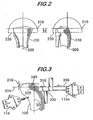
- FIG. 2 illustrates front and side views of a tibia 102.
- the illustrated views are generated by the localization device 100 of FIG. 1 for display on the monitor 118 during a tibia cutting jig navigation step.
- the surgeon Prior to the navigation step, the surgeon, using the localization device 100, acquires reference features associated with the tibia 120 in a known manner for use in the navigation.
- the reference features include a mechanical axis 200 of the tibia 120, a knee joint interline 210, and a desired cutting plane 220.
- the mechanical axis 200 of the tibia 120 which extends through the center of the knee and the center of the ankle, is determined using the localization device in a known manner.
- the knee joint interline 210 which represents a physical point of contact between the tibia 120 and the femur 124. (FIG. 1), may be determined by physically palpating one or more points on the knee joint interline 210 on the tibia 120 in a known manner using a pointer containing a marker being tracked by the localization device, which records the positions of the palpated points by detecting the position of the pointer relative to the markers fixedly mounted to the bones when the points are palpated.
- the desired cutting plane 220 which represents where the tibia 120 should be cut, is oriented such that the mechanical axis 210 of the tibia 120 is normal to the desired cutting plane 210 and the desired cutting plane is a predefined distance, d (e.g., 8 millimeters), from the knee joint interline 210 as measured along the mechanical axis 200 of the tibia 120.
- the localization device receives the predefined distance from a surgeon through the keyboard 117 (FIG. 1).
- FIG. 3 depicts a cutting jig 300 positioned on the tibia 120.
- the cutting jig 300 contains a cutting guide 310 that defines a cutting plane 320 (represented by a line in FIG. 3) for guiding a cutting blade 330 of a saw (not shown).
- the cutting jig 300 is capable of receiving a marker 116a for tracking by the localization device 100 (FIG. 1).
- the marker 116a can be mounted on the cutting jig 300 in only one predetermined way and the localization device 100 is preprogrammed with data indicating the orientation and position of the cutting plane 320 relative to the marker 116a.
- the localization device 100 is also preprogrammed with data indicating the position of a predefined point 325 on the cutting plane 320 relative to the marker 116a.
- the localization device 100 can determine the position and orientation of the cutting plane 320 of the cutting jig 300 and the position of the predefined point 325 relative to other points known to the localization device 110, e.g., a palpated point 340 on the knee joint interline 210 of the tibia 120 in the frame of reference of the tibia (the frame of reference being defined by the position of the tibial marker).
- Positional parameters associated with the cutting jig 300 are developed by the localization device 100.
- the positional parameters are one or more parameters associated with the cutting jig 300 in one or more frames of reference for use in guiding a surgeon during the navigation of the cutting jig 300.
- the positional parameters for the cutting jig 300 include an angular measurement and a linear measurement in the frame of reference of the tibia 120. The angular measurement represents an angle between the mechanical axis 200 of the tibia 120 and a vector normal to the cutting plane 320 of the cutting jig 300.
- the angular positional parameter is that the difference between the mechanical axis 200 or the tibia 120 and a vector normal to the cutting plane 320 of the cutting jig 300 is 3 degrees or less.
- the linear measurement represents the linear distance, d', of a vector component parallel to the mechanical axis 200 of the tibia 120 for a vector extending between a point on the cutting plane 320 and a point on the knee joint interline 210.
- the point on the cutting plane 320 is the predefined point 325
- the point on the knee joint interline 210 is the palpated point 340
- the linear positional parameter is that the distance between the point on the cutting plane and the point on the knee joint interline is greater than 5 millimeters and less than 20 millimeters.
- the positional parameters associated with the cutting jig 300 were recorded when the surgeon instructed the localization device 100 to proceed to the next step of the procedure, e.g., by depressing the foot pedal 115 (FIG. 1) coupled to the localization device 100. If the marker 116a attached to the cutting jig is removed prior to the surgeon's instruction to proceed, the positional parameters recorded by the localization device 100 will not accurately represent the positional parameters of the cutting jig.
- FIG. 4 depicts a flow chart 400 for a preferred method for automatically recording accurate positional parameters associated with a navigated surgical tool (hereinafter the "tool"), e.g. the cutting jig 300 in the exemplary embodiment.
- the method begins.
- the method begins when invoked by the localization device 100 during one or more specific portions of a procedure.
- the localization device 100 may invoke the method during the navigation of a cutting jig 300 (FIG. 3) used to guide a saw blade 330 in the removal of a portion of a tibia 120 during a TKA procedure.
- expected positional parameters associated with the tool are identified.
- the expected positional parameters represent ideal parameters associated with a properly navigated tool.
- the cutting jig 300 depicted in FIG. 3 in accordance with one embodiment, the cutting jig 300 is properly navigated when the cutting plane 320 is perpendicular to the mechanical axis 200 of the tibia 120 and the cutting plane 320 is a predefined distance from the knee joint interline 210.
- the expected positional parameters associated with the cutting jig 300 include an angular component and a spatial component:
- the angular component is an angle between the mechanical axis 200 of the tibia 120 and a vector normal to the expected cutting plane 220 (FIG. 2), which, preferably, is approximately zero degrees.
- the angular component is represented using two angular parameters about two axes, respectively, e.g., a first axis perpendicular to the mechanical axis 200 and parallel to the knee joint interline 210 and a second axis perpendicular to both the mechanical axis 200 and the knee joint interline 210.
- the orientation of a plane can be expressed using two angles since the rotation of the plane about an axis normal to the plane, e.g., the mechanical axis 200, is irrelevant.
- the spatial component is a predefined spatial parameter representing a distance, d (FIG. 2), e.g., approximately 8 millimeters, from the knee joint interline 210 in a direction parallel to the mechanical axis 200 of the tibia 120.
- d a distance
- the expected positional parameters can be represented by two angular parameters and one spatial parameter, the expected positional parameters may include essentially any number and type of parameters.
- an area of interest specifies the tolerances for the expected positional parameters identified in block 404.
- a separate tolerance value is specified for each identified expected positional parameter.
- the expected positional parameters at block 404 were represented in terms of one spatial parameter and two angular parameters.
- the spatial parameter which is a predefined distance d from the knee joint interline 210, includes a range of distances for this parameter, e.g., from 5 millimeters to 20 millimeters.
- the two angular parameters which are expressed in terms of an angular relationship, e.g., 0 degrees to a vector normal to the cutting plane, may include a range of angles for these parameters, e.g., up to 3 degrees for each of the angular parameters.
- the position of the tool is monitored by the localization device 100.
- the position of the cutting jig 300 is monitored by tracking the marker 116a attached to the cutting jig 300 in a frame of reference for the tibia 120.
- the localization device 100 is preprogrammed with instructions that define the orientation of the cutting plane 320 of the cutting jig 300 and further define a point 325 on that cutting plane 320, e.g., a point in space one centimeter from the leading edge of the cutting guide 310 of the cutting jig 300.
- the position of the cutting jig 300 may be expressed in terms of the orientation of the cutting plane 320 and in terms of the location of the predefined point 325 in space in the tibia's frame of reference.
- the orientation of the cutting plane 320 is represented using two angles and the location of the predefined point 325 is represented using a three dimensional coordinate system.
- the position of the cutting jig 300 is continuously monitored throughout the rest of the steps of flow chart 400.
- actual positional parameters associated with the tool are calculated.
- each of the actual positional parameters corresponds to one of the expected positional parameters identified at block 404.
- the actual positional parameters associated with the cutting jig 300 include two angular parameters and a spatial parameter.
- the angles between the mechanical axis and a vector normal to the cutting plane 320 of the cutting jig 300 about a first axis and a second axis are calculated.
- the localization device 100 determines the angular parameters by calculating a vector normal to the cutting plane 320 in a known manner using the tool positions monitored at block 408 and comparing the calculated value to the mechanical axis 200 of the tibia 120.
- the vector component parallel to the mechanical axis 200 of the tibia 120 is calculated for a vector that extends between the predefined point 325 on the cutting plane 320 and the palpated point 340 on the knee joint interline 210.
- the localization device 100 determines the spatial parameter by calculating the vector component parallel to the mechanical axis 200 of the tibia 120 for a vector extending between the predefined point 325 on the cutting plane 320 and the palpated point 340 on the knee joint interline 210.
- the actual positional parameters of the tool calculated at block 410 are compared to the expected positional parameters identified at block 404 to determine if they conform to the area of interest defined at block 406.
- the localization device 100 determines if the actual positional parameters are within the area of interest by comparing them to the expected positional parameters to see if each one of the actual positional parameters conform to the area of interest surrounding the corresponding expected positional parameters. If every one of the actual positional parameters conform to the area of interest surrounding the corresponding expected positional parameters, the actual positional parameters conform to the area of interest and processing proceeds to block 414.
- an indicator is generated at block 418, such as a prompt to display a message indicating that the actual positional parameters are "Not in Area of Interest" for display on a monitor 118 (FIG. 1) of the localization device 100.
- the stability of the tool is determined.
- the tool is deemed stable if a portion of the tool is stationary for a specified period of time, e.g., greater than about 3 seconds and, preferably, greater than about 6 seconds.
- the tool is stationary if the tool moves less than a predefined distance, e.g., 0.5 millimeters, in any spatial direction and rotates less than a predefined amount, e.g., 0.5 degrees, in any angular direction. If the tool is stable, processing proceeds to block 416.
- an indicator is generated at block 420, such as a prompt to display a message indicating that the cutting jig is ANot Stable@ for display on the monitor 118 (FIG. 1) of the localization device 100.
- the localization device 100 determines if the cutting jig 300 is stable by tracking the position of the cutting jig 300 as monitored at block 408 for the specified period of time.
- the surgical tool may be considered stable if a specific portion of the surgical tool, e.g., the tip of the pointer, moves less than a predetermined amount during a predetermined period of time since stability in the orientation of certain surgical tools, e.g., a pointer, is typically not as crucial as stability in a portion of the tool, e.g., the pointer tip.
- the positional parameters associated with the tool are recorded.
- the localization device may record the positional parameters in a conventional memory 110 (FIG. 1).
- positional parameters for the last stable position of the tool are recorded with positional parameters for previous stable positions of the tool, if any, being overwritten by positional parameters for more recent stable positions.
- positional parameters for each stable position are recorded.
- the surgeon indicates when that portion of the procedure is finished, e.g., by depressing a foot pedal. If the portion of the procedure is finished, processing proceeds to block 424. Otherwise, if the portion of the procedure is not finished, processing proceeds back to block 410 so that the-device-can-continue to collect and record positional parameters as described in connection with steps 412 to 420.
- the surgeon may still manually prompt the localization device to record positional parameters.
- the surgeon may depress a foot pedal 115 (FIG. 1) or a key of a keyboard 117 (FIG. 1) when the surgeon desires to record positional parameters associated with the cutting jig.
- the positional parameters recorded upon prompting by the surgeon may be stored in addition to positional parameters automatically recorded in accordance with the present invention or may replace one or more automatically recorded positional parameters.
- the surgeon may desire to record positional parameters when the surgeon believes that the cutting jig is properly positioned, rather than rely solely on the automated recording described hereinabove and in connection with FIG. 4.
- the positional parameters recorded at the surgeon's prompting may be useful during post operative analysis for comparison to automatically recorded positional parameters obtained through the steps of blocks 410-422 for verification of the accuracy of the automatically recorded positional parameters.
Landscapes
- Health & Medical Sciences (AREA)
- Surgery (AREA)
- Engineering & Computer Science (AREA)
- Life Sciences & Earth Sciences (AREA)
- Biomedical Technology (AREA)
- Robotics (AREA)
- Nuclear Medicine, Radiotherapy & Molecular Imaging (AREA)
- Heart & Thoracic Surgery (AREA)
- Medical Informatics (AREA)
- Molecular Biology (AREA)
- Animal Behavior & Ethology (AREA)
- General Health & Medical Sciences (AREA)
- Public Health (AREA)
- Veterinary Medicine (AREA)
- Surgical Instruments (AREA)
Description
- The present invention relates to medical instruments and, more particularly, to a non-surgical method and an apparatus for recording positional parameters associated with a tool that is tracked by a localization device.
- Localization devices have been developed to assist surgeons in performing surgical procedures. Markers are attached to bones that are observable by a stereoscopic camera system connected to a data processing system that records the positions of the markers in space to establish a coordinate reference system relative to each bone. Additional markers are attached to tools used during the surgical procedures. Typically, these markers are removable so that one marker can be used with multiple tools as needed during a procedure. By tracking the marker associated with a tool, positional parameters associated with the tool can be tracked in the coordinate reference systems of the bones. A monitor displays a representation of the bones and the position of the tools in the coordinate reference systems of the bones for use in guiding a surgeon during surgical procedures. A description of one particular localization device is described in
U.S. Patent No. 6,385,475 to Cinquin et al. . - Surgical procedures performed using a localization device are typically carried out in a number of sequential steps. For example, to make a cut in a bone, initially, a number of steps are performed using the localization device in order to establish a coordinate reference system and to determine the precise angle and depth of the cut to be made in the bone. The localization device is then used in a first navigation step to guide a surgeon, in the placement of a cutting jig, which contains a cutting guide used to guide a saw in a cutting plane defined by the cutting guide. A removable marker attached to the cutting jig allows the localization device to track the cutting jig to obtain information for use in performing the first navigation step. Once the cutting jig is in place, it is secured to the bone with pins. After the cutting jig is secured, the removable marker is removed from the cutting jig for later attachment to tools used in subsequent navigation steps.
- Often, during a procedure, it is desirable to record positional parameters associated with a tool at the end of a navigation step for post operative analysis. For example, when making a cut in a bone, it is desirable to record the angle of the cutting plane defined by the cutting guide of a cutting jig and the distance of the cutting plane from a reference point on the bone to determine if the cutting jig was positioned properly or to compare the positional parameters of the cutting jig to the positional parameters of cutting jigs in similar procedures and their roles in the success or failure of a procedure. Ideally, when a surgeon finishes a navigation step, prior to the removal of the marker from the tool being navigated, the surgeon provides an indication to the localization device that this step of the procedure is over, e.g., by depressing a foot switch coupled to the localization device. The localization device then records the positional parameters associated with the tool. Sometimes, however, the surgeon removes the marker prior to indicating that this step of the procedure is over. Thus, since the marker is no longer associated with the tool, the positional parameters recorded by the localization device will not represent the actual positional parameters associated with the tool. Hence, the recorded positional parameters will be useless.
- A surgeon's primary focus during a procedure is the successful completion of that particular procedure. Thus, steps that are not critical to the success of the operation may be seen as burdensome to the surgeon. Therefore, the surgeon may neglect to perform inconvenient tasks such as indicating that a navigation step is over prior to removal of the marker from the tool being navigated if it is not critical to the present procedure and the only reason for doing so is the accumulation of data for post operative analysis.
- Accordingly, a convenient method is needed that ensures navigated tool positional parameters are accurately recorded.
- The present invention provides a non-surgical method and an apparatus for accurately recording positional parameters associated with a tool that is navigated using a localization device. The aforementioned problems are overcome by automatically recording the positional parameters associated with the tool in the last stable position of the tool when the positional parameters are within a defined area of interest. By automatically recording the positional parameters during the last stable position of the tool, accurate positional parameters can be ascertained without additional input. Thus, navigated tool positional parameters may be recorded conveniently and accurately.
- One aspect of the present invention is a non-surgical method of recording tool positional parameters with a localization device. The method includes monitoring the position of a tool with the localization device and recording at least one positional parameter associated with the tool if a portion of the tool is moved less than a predetermined amount over a predetermined period of time.
- Another aspect of the invention is a localization system for automatically recording positional parameters associated with a tool. The localization system includes sensors for tracking a marker associated with a tool and a computer coupled to the sensors for monitoring the position of the tool, calculating at least one positional parameter associated with the tool, and recording the at least one positional parameter when a portion of the tool is moved less than a predetermined amount over a predetermined period of time.
- The steps of the method may be embodied in a computer readable medium or may form a system comprising means for performing the method steps.
- In the drawings, the same reference numerals are used to indicate the same elements.
- Figure 1 is an illustration of a patient about to undergo a procedure utilizing a localization device in accordance with the present invention;
- Figure 2 is an illustration of a tibia represented by the localization device of figure 1 during a TKA procedure;
- Figure 3 is an illustration depicting positional parameters associated with a cutting jig used in a TKA procedure; and
- Figure 4 is a flow chart depicting steps for automatically recording positional parameters associated with a tool being navigated utilizing a localization device in accordance with the present invention.
- FIG. 1 depicts a
localization device 100 in which the method of the present invention may be employed. In FIG. 1, apatient 102, who is to undergo a procedure, e.g., a Total Knee Arthroplasty (TKA) procedure on aleg 104, is illustrated schematically lying on an operating table 106. Thelocalization device 100 includes acomputer 108 loaded with software for surgical navigation, amemory 110, aprocessor 112,sensors 114, e.g., cameras, capable of detectingmarkers 116,foot pedals 115, akeyboard 117, and amonitor 118 for displaying surgical navigation information to a surgeon to guide the surgeon during the procedure. Thesensors 114 are positioned above and laterally from thepatient 102 so that the patient'sleg 104 is in the field of view of thesensors 114. In general, themarkers 116 are fixedly mounted on bones and surgical tools so that thelocalization device 100 can track the exact location and orientation of the bones and surgical tools to which they are mounted. A description of asuitable localization device 100 and method is found inU.S. Patent No. 6,385,475 to Cinquin et al. , having a common inventor and commonly assigned to the same entity as the present application, incorporated herein in full by reference. - For descriptive purposes, an exemplary embodiment of the present invention will be described in connection with the navigation of a cutting jig (see description of FIG. 3 below) for guiding a saw blade in the removal of a portion of a
tibia 120 during one step of a TKA procedure. The TKA procedure involves replacing the damaged knee 122 by resurfacing thetibia 120 and femur 124 at the knee 122 with metal and/or plastic prostheses to form an artificial joint. The procedure involves sawing off the ends of thetibia 120 and femur 124 near the knee 122 very precisely to create surfaces of precise shape and location to accept the prostheses. Although the description of the present invention focuses on recording positional parameters associated with a cutting jig navigated by a localization device during a TKA procedure, it will be readily apparent to those skilled in the art that the present invention may be used with any number of surgical tools in any number of procedures. - FIG. 2 illustrates front and side views of a
tibia 102. The illustrated views are generated by thelocalization device 100 of FIG. 1 for display on themonitor 118 during a tibia cutting jig navigation step. Prior to the navigation step, the surgeon, using thelocalization device 100, acquires reference features associated with thetibia 120 in a known manner for use in the navigation. The reference features include amechanical axis 200 of thetibia 120, aknee joint interline 210, and a desiredcutting plane 220. Themechanical axis 200 of thetibia 120, which extends through the center of the knee and the center of the ankle, is determined using the localization device in a known manner. The kneejoint interline 210, which represents a physical point of contact between thetibia 120 and the femur 124. (FIG. 1), may be determined by physically palpating one or more points on theknee joint interline 210 on thetibia 120 in a known manner using a pointer containing a marker being tracked by the localization device, which records the positions of the palpated points by detecting the position of the pointer relative to the markers fixedly mounted to the bones when the points are palpated. The desiredcutting plane 220, which represents where thetibia 120 should be cut, is oriented such that themechanical axis 210 of thetibia 120 is normal to the desiredcutting plane 210 and the desired cutting plane is a predefined distance, d (e.g., 8 millimeters), from theknee joint interline 210 as measured along themechanical axis 200 of thetibia 120. In one embodiment, the localization device receives the predefined distance from a surgeon through the keyboard 117 (FIG. 1). - FIG. 3 depicts a
cutting jig 300 positioned on thetibia 120. Thecutting jig 300 contains acutting guide 310 that defines a cutting plane 320 (represented by a line in FIG. 3) for guiding acutting blade 330 of a saw (not shown). The cuttingjig 300 is capable of receiving amarker 116a for tracking by the localization device 100 (FIG. 1). Themarker 116a can be mounted on the cuttingjig 300 in only one predetermined way and thelocalization device 100 is preprogrammed with data indicating the orientation and position of the cuttingplane 320 relative to themarker 116a. Preferably, thelocalization device 100 is also preprogrammed with data indicating the position of apredefined point 325 on the cuttingplane 320 relative to themarker 116a. By observing themarker 116a, thelocalization device 100 can determine the position and orientation of the cuttingplane 320 of the cuttingjig 300 and the position of thepredefined point 325 relative to other points known to thelocalization device 110, e.g., a palpatedpoint 340 on the kneejoint interline 210 of thetibia 120 in the frame of reference of the tibia (the frame of reference being defined by the position of the tibial marker). - Positional parameters associated with the cutting
jig 300 are developed by thelocalization device 100. In a preferred embodiment, the positional parameters are one or more parameters associated with the cuttingjig 300 in one or more frames of reference for use in guiding a surgeon during the navigation of the cuttingjig 300. In one embodiment, the positional parameters for the cuttingjig 300 include an angular measurement and a linear measurement in the frame of reference of thetibia 120. The angular measurement represents an angle between themechanical axis 200 of thetibia 120 and a vector normal to the cuttingplane 320 of the cuttingjig 300. In one preferred embodiment, the angular positional parameter is that the difference between themechanical axis 200 or thetibia 120 and a vector normal to the cuttingplane 320 of the cuttingjig 300 is 3 degrees or less. The linear measurement represents the linear distance, d', of a vector component parallel to themechanical axis 200 of thetibia 120 for a vector extending between a point on the cuttingplane 320 and a point on the kneejoint interline 210. In a preferred embodiment, the point on the cuttingplane 320 is thepredefined point 325, the point on the kneejoint interline 210 is the palpatedpoint 340, and the linear positional parameter is that the distance between the point on the cutting plane and the point on the knee joint interline is greater than 5 millimeters and less than 20 millimeters. - For post operative analysis, it is useful to record the positional parameters associated with the cutting
jig 300 after it is secured to thetibia 120. Prior to the present invention, the positional parameters of the cuttingjig 300 were recorded when the surgeon instructed thelocalization device 100 to proceed to the next step of the procedure, e.g., by depressing the foot pedal 115 (FIG. 1) coupled to thelocalization device 100. If themarker 116a attached to the cutting jig is removed prior to the surgeon's instruction to proceed, the positional parameters recorded by thelocalization device 100 will not accurately represent the positional parameters of the cutting jig. - FIG. 4 depicts a
flow chart 400 for a preferred method for automatically recording accurate positional parameters associated with a navigated surgical tool (hereinafter the "tool"), e.g. the cuttingjig 300 in the exemplary embodiment. Atblock 402, the method begins. In a preferred embodiment, the method begins when invoked by thelocalization device 100 during one or more specific portions of a procedure. For example, thelocalization device 100 may invoke the method during the navigation of a cutting jig 300 (FIG. 3) used to guide asaw blade 330 in the removal of a portion of atibia 120 during a TKA procedure. - At
block 404, expected positional parameters associated with the tool are identified. The expected positional parameters represent ideal parameters associated with a properly navigated tool. For theexemplary cutting jig 300 depicted in FIG. 3, in accordance with one embodiment, the cuttingjig 300 is properly navigated when the cuttingplane 320 is perpendicular to themechanical axis 200 of thetibia 120 and the cuttingplane 320 is a predefined distance from the kneejoint interline 210. Thus, in this embodiment, the expected positional parameters associated with the cuttingjig 300 include an angular component and a spatial component: - The angular component is an angle between the
mechanical axis 200 of thetibia 120 and a vector normal to the expected cutting plane 220 (FIG. 2), which, preferably, is approximately zero degrees. Preferably, the angular component is represented using two angular parameters about two axes, respectively, e.g., a first axis perpendicular to themechanical axis 200 and parallel to the kneejoint interline 210 and a second axis perpendicular to both themechanical axis 200 and the kneejoint interline 210. As will be readily apparent to those skilled in the art, the orientation of a plane can be expressed using two angles since the rotation of the plane about an axis normal to the plane, e.g., themechanical axis 200, is irrelevant. The spatial component is a predefined spatial parameter representing a distance, d (FIG. 2), e.g., approximately 8 millimeters, from the kneejoint interline 210 in a direction parallel to themechanical axis 200 of thetibia 120. It will be noted by those skilled in the art that, although in the present example the expected positional parameters can be represented by two angular parameters and one spatial parameter, the expected positional parameters may include essentially any number and type of parameters. - At
block 406, an area of interest is defined: The defined area of interest specifies the tolerances for the expected positional parameters identified inblock 404. Preferably, a separate tolerance value is specified for each identified expected positional parameter. For theexemplary cutting jig 300, the expected positional parameters atblock 404 were represented in terms of one spatial parameter and two angular parameters. In this embodiment, the spatial parameter, which is a predefined distance d from the kneejoint interline 210, includes a range of distances for this parameter, e.g., from 5 millimeters to 20 millimeters. Likewise, the two angular parameters, which are expressed in terms of an angular relationship, e.g., 0 degrees to a vector normal to the cutting plane, may include a range of angles for these parameters, e.g., up to 3 degrees for each of the angular parameters. - At
block 408, the position of the tool is monitored by thelocalization device 100. For theexemplary cutting jig 300, the position of the cuttingjig 300 is monitored by tracking themarker 116a attached to the cuttingjig 300 in a frame of reference for thetibia 120. In one embodiment, as described above, thelocalization device 100 is preprogrammed with instructions that define the orientation of the cuttingplane 320 of the cuttingjig 300 and further define apoint 325 on that cuttingplane 320, e.g., a point in space one centimeter from the leading edge of the cuttingguide 310 of the cuttingjig 300. Thus, the position of the cuttingjig 300 may be expressed in terms of the orientation of the cuttingplane 320 and in terms of the location of thepredefined point 325 in space in the tibia's frame of reference. In this embodiment, the orientation of the cuttingplane 320 is represented using two angles and the location of thepredefined point 325 is represented using a three dimensional coordinate system. The position of the cuttingjig 300 is continuously monitored throughout the rest of the steps offlow chart 400. - At
block 410, actual positional parameters associated with the tool are calculated. For theexemplary cutting jig 300, each of the actual positional parameters corresponds to one of the expected positional parameters identified atblock 404. Thus, the actual positional parameters associated with the cuttingjig 300 include two angular parameters and a spatial parameter. To determine the angular parameters, the angles between the mechanical axis and a vector normal to the cuttingplane 320 of the cuttingjig 300 about a first axis and a second axis are calculated. Preferably, thelocalization device 100 determines the angular parameters by calculating a vector normal to the cuttingplane 320 in a known manner using the tool positions monitored atblock 408 and comparing the calculated value to themechanical axis 200 of thetibia 120. To determine the spatial parameter, the vector component parallel to themechanical axis 200 of thetibia 120 is calculated for a vector that extends between thepredefined point 325 on the cuttingplane 320 and the palpatedpoint 340 on the kneejoint interline 210. Preferably, thelocalization device 100 determines the spatial parameter by calculating the vector component parallel to themechanical axis 200 of thetibia 120 for a vector extending between thepredefined point 325 on the cuttingplane 320 and the palpatedpoint 340 on the kneejoint interline 210. - At
block 412, the actual positional parameters of the tool calculated atblock 410 are compared to the expected positional parameters identified atblock 404 to determine if they conform to the area of interest defined atblock 406. Thelocalization device 100 determines if the actual positional parameters are within the area of interest by comparing them to the expected positional parameters to see if each one of the actual positional parameters conform to the area of interest surrounding the corresponding expected positional parameters. If every one of the actual positional parameters conform to the area of interest surrounding the corresponding expected positional parameters, the actual positional parameters conform to the area of interest and processing proceeds to block 414. Otherwise, if the actual positional parameters do not conform, an indicator is generated atblock 418, such as a prompt to display a message indicating that the actual positional parameters are "Not in Area of Interest" for display on a monitor 118 (FIG. 1) of thelocalization device 100. - At
block 414, the stability of the tool is determined. In a preferred embodiment, the tool is deemed stable if a portion of the tool is stationary for a specified period of time, e.g., greater than about 3 seconds and, preferably, greater than about 6 seconds. Preferably, the tool is stationary if the tool moves less than a predefined distance, e.g., 0.5 millimeters, in any spatial direction and rotates less than a predefined amount, e.g., 0.5 degrees, in any angular direction. If the tool is stable, processing proceeds to block 416. Otherwise, if the tool is not stable, an indicator is generated atblock 420, such as a prompt to display a message indicating that the cutting jig is ANot Stable@ for display on the monitor 118 (FIG. 1) of thelocalization device 100. For theexemplary cutting jig 300, thelocalization device 100 determines if the cuttingjig 300 is stable by tracking the position of the cuttingjig 300 as monitored atblock 408 for the specified period of time. If the orientation of the cuttingplane 320 represented using two angles at block 308 rotates less than the predefined amount in each angular direction and the location of thepredefined point 325 represented using a three dimensional coordinate system moves less than the predefined distance in any direction for the predefined period of time, the cuttingjig 300 is stable and processing proceeds to block 416. Otherwise, processing proceeds to block 420. For other surgical tools, such as a pointer, it is contemplated that the surgical tool may be considered stable if a specific portion of the surgical tool, e.g., the tip of the pointer, moves less than a predetermined amount during a predetermined period of time since stability in the orientation of certain surgical tools, e.g., a pointer, is typically not as crucial as stability in a portion of the tool, e.g., the pointer tip. - At
block 416, the positional parameters associated with the tool, e.g., the cuttingjig 300, are recorded. The localization device may record the positional parameters in a conventional memory 110 (FIG. 1). In one embodiment, only the positional parameters for the last stable position of the tool are recorded with positional parameters for previous stable positions of the tool, if any, being overwritten by positional parameters for more recent stable positions. In an alternative embodiment, positional parameters for each stable position are recorded. - At
block 422, a determination is made as to whether the specific portion of the procedure in which the method was invoked inblock 402 is finished. In a preferred embodiment, the surgeon indicates when that portion of the procedure is finished, e.g., by depressing a foot pedal. If the portion of the procedure is finished, processing proceeds to block 424. Otherwise, if the portion of the procedure is not finished, processing proceeds back to block 410 so that the-device-can-continue to collect and record positional parameters as described in connection withsteps 412 to 420. - In one embodiment, the surgeon may still manually prompt the localization device to record positional parameters. For example, the surgeon may depress a foot pedal 115 (FIG. 1) or a key of a keyboard 117 (FIG. 1) when the surgeon desires to record positional parameters associated with the cutting jig. The positional parameters recorded upon prompting by the surgeon may be stored in addition to positional parameters automatically recorded in accordance with the present invention or may replace one or more automatically recorded positional parameters. The surgeon may desire to record positional parameters when the surgeon believes that the cutting jig is properly positioned, rather than rely solely on the automated recording described hereinabove and in connection with FIG. 4. The positional parameters recorded at the surgeon's prompting may be useful during post operative analysis for comparison to automatically recorded positional parameters obtained through the steps of blocks 410-422 for verification of the accuracy of the automatically recorded positional parameters.
- Although the present invention has been described in terms of recording the last stable position of a cutting jig during a cutting jig navigation step of a TKA procedure, it will be readily apparent to those skilled in the art that the present invention may be used to record the position of essentially any tool during steps of essentially any procedure in which a localization device is employed.
- Having thus described a few particular embodiments of the invention, various alterations, modifications, and improvements will readily occur to those skilled in the art. Such alterations, modifications and improvements as are made obvious by this disclosure are intended to be part of this description though not expressly stated herein, and are intended to be within the spirit and scope of the invention. Accordingly, the foregoing description is by way of example only, and not limiting. The invention is limited only as defined in the following claims and equivalents thereto.
Claims (15)
- A non-surgical method for recording positional parameters of a tool navigated using a localization device, the method comprising the steps of:monitoring the position of a tool with said localization device; andautomatically recording at least one positional parameter associated with said tool if a portion of said tool is moved less than a predetermined amount over a predetermined period of time.
- The method of claim 1, wherein said tool is capable of receiving a marker for tracking by the localization device to enable monitoring of the position of said tool.
- The method of claim 1, further comprising the steps of:defining an area of interest for said at least one positional parameter; anddetermining if said at least one positional parameter conforms to said area of interest, wherein said at least one positional parameters is recorded only if said at least one positional parameter conforms to said area of interest.
- The method of claim 3, wherein said area of interest defines tolerances for said at least one positional parameter.
- The method of claim 3, further comprising the step of:generating a first indicator if said at least one positional parameter does not conform with said area of interest.
- The method of claim 5, further comprising the step of:generating a second indicator if said tool does not move less than said predetermined amount over said predetermined period of time.
- The method of claim 1, wherein said predefined period of time is greater than about 3 seconds.
- The method of claim 1, wherein said predetermined amount is less than about 0.5 millimeters in any direction.
- The method of claim 1, wherein said predetermined amount is less than 0.5 millimeters in any spatial direction and less than 0.5 degrees in any angular direction.
- A localization system comprising:sensors for tracking a marker associated with a tool; anda computer coupled to said sensors for monitoring the position of said tool, calculating at least one positional parameter based on the monitored position, and automatically recording the at least one calculated positional parameter if a portion of said tool moves less than a predetermined amount during a predetermined period of time.
- The system of claim 10, wherein said computer further identifies an area of interest associated with at least one expected positional parameter and only records the at least one calculated positional parameter if said at least one calculated positional parameter conforms to said area of interest.
- The system of claim 10 or 11, further comprising at least:a monitor coupled to said computer, wherein said computer causes said monitor to display a first message when said at least one calculated positional parameter does not conform to said area of interest.
- The system of claim 12, wherein said computer causes said monitor to display a second message when said tool does not move more than a predefined amount over a predetermined period of time.
- A computer program product for recording tool positions with a localization device, said computer program product comprising:computer readable program code embodied in a computer readable medium, the computer readable program code comprising at least:computer readable program code for monitoring the position of a tool with said localization device; andcomputer readable program code for automatically recording at least one positional parameter associated with said tool if a portion of said tool is moved less than a predetermined amount over a predetermined period of time.
- The product of claim 14, further comprising:computer readable program code for defining an area of interest for said at least one positional parameter; andcomputer readable program code for determining if said at least one positional parameter conforms to said area of interest, wherein said at least one positional parameters is recorded only if said at least one positional parameter conforms to said area of interest.
Applications Claiming Priority (3)
| Application Number | Priority Date | Filing Date | Title |
|---|---|---|---|
| US348583 | 2003-01-21 | ||
| US10/348,583 US8355773B2 (en) | 2003-01-21 | 2003-01-21 | Recording localization device tool positional parameters |
| PCT/EP2004/000396 WO2004064659A1 (en) | 2003-01-21 | 2004-01-20 | Method end device for recording localization device tool positional parameters |
Publications (2)
| Publication Number | Publication Date |
|---|---|
| EP1589891A1 EP1589891A1 (en) | 2005-11-02 |
| EP1589891B1 true EP1589891B1 (en) | 2007-11-28 |
Family
ID=32712584
Family Applications (1)
| Application Number | Title | Priority Date | Filing Date |
|---|---|---|---|
| EP04703375A Expired - Lifetime EP1589891B1 (en) | 2003-01-21 | 2004-01-20 | Method and device for recording localization device tool positional parameters |
Country Status (5)
| Country | Link |
|---|---|
| US (1) | US8355773B2 (en) |
| EP (1) | EP1589891B1 (en) |
| DE (1) | DE602004010365T2 (en) |
| ES (1) | ES2294458T3 (en) |
| WO (1) | WO2004064659A1 (en) |
Families Citing this family (87)
| Publication number | Priority date | Publication date | Assignee | Title |
|---|---|---|---|---|
| US7559931B2 (en) | 2003-06-09 | 2009-07-14 | OrthAlign, Inc. | Surgical orientation system and method |
| US8608748B2 (en) * | 2006-02-27 | 2013-12-17 | Biomet Manufacturing, Llc | Patient specific guides |
| US7967868B2 (en) | 2007-04-17 | 2011-06-28 | Biomet Manufacturing Corp. | Patient-modified implant and associated method |
| US8377066B2 (en) | 2006-02-27 | 2013-02-19 | Biomet Manufacturing Corp. | Patient-specific elbow guides and associated methods |
| US8407067B2 (en) | 2007-04-17 | 2013-03-26 | Biomet Manufacturing Corp. | Method and apparatus for manufacturing an implant |
| US8133234B2 (en) | 2006-02-27 | 2012-03-13 | Biomet Manufacturing Corp. | Patient specific acetabular guide and method |
| US8858561B2 (en) * | 2006-06-09 | 2014-10-14 | Blomet Manufacturing, LLC | Patient-specific alignment guide |
| US8568487B2 (en) * | 2006-02-27 | 2013-10-29 | Biomet Manufacturing, Llc | Patient-specific hip joint devices |
| US9918740B2 (en) | 2006-02-27 | 2018-03-20 | Biomet Manufacturing, Llc | Backup surgical instrument system and method |
| US9345548B2 (en) | 2006-02-27 | 2016-05-24 | Biomet Manufacturing, Llc | Patient-specific pre-operative planning |
| US20110190899A1 (en) * | 2006-02-27 | 2011-08-04 | Biomet Manufacturing Corp. | Patient-specific augments |
| US8591516B2 (en) | 2006-02-27 | 2013-11-26 | Biomet Manufacturing, Llc | Patient-specific orthopedic instruments |
| US9173661B2 (en) | 2006-02-27 | 2015-11-03 | Biomet Manufacturing, Llc | Patient specific alignment guide with cutting surface and laser indicator |
| US8241293B2 (en) | 2006-02-27 | 2012-08-14 | Biomet Manufacturing Corp. | Patient specific high tibia osteotomy |
| US8608749B2 (en) * | 2006-02-27 | 2013-12-17 | Biomet Manufacturing, Llc | Patient-specific acetabular guides and associated instruments |
| US8535387B2 (en) * | 2006-02-27 | 2013-09-17 | Biomet Manufacturing, Llc | Patient-specific tools and implants |
| US8092465B2 (en) | 2006-06-09 | 2012-01-10 | Biomet Manufacturing Corp. | Patient specific knee alignment guide and associated method |
| US9113971B2 (en) | 2006-02-27 | 2015-08-25 | Biomet Manufacturing, Llc | Femoral acetabular impingement guide |
| US20150335438A1 (en) | 2006-02-27 | 2015-11-26 | Biomet Manufacturing, Llc. | Patient-specific augments |
| US9339278B2 (en) | 2006-02-27 | 2016-05-17 | Biomet Manufacturing, Llc | Patient-specific acetabular guides and associated instruments |
| US8603180B2 (en) * | 2006-02-27 | 2013-12-10 | Biomet Manufacturing, Llc | Patient-specific acetabular alignment guides |
| US9289253B2 (en) * | 2006-02-27 | 2016-03-22 | Biomet Manufacturing, Llc | Patient-specific shoulder guide |
| US20110172672A1 (en) * | 2006-02-27 | 2011-07-14 | Biomet Manufacturing Corp. | Instrument with transparent portion for use with patient-specific alignment guide |
| US8864769B2 (en) * | 2006-02-27 | 2014-10-21 | Biomet Manufacturing, Llc | Alignment guides with patient-specific anchoring elements |
| US9907659B2 (en) | 2007-04-17 | 2018-03-06 | Biomet Manufacturing, Llc | Method and apparatus for manufacturing an implant |
| US10278711B2 (en) * | 2006-02-27 | 2019-05-07 | Biomet Manufacturing, Llc | Patient-specific femoral guide |
| US20070238981A1 (en) * | 2006-03-13 | 2007-10-11 | Bracco Imaging Spa | Methods and apparatuses for recording and reviewing surgical navigation processes |
| US9795399B2 (en) | 2006-06-09 | 2017-10-24 | Biomet Manufacturing, Llc | Patient-specific knee alignment guide and associated method |
| GB2442441B (en) | 2006-10-03 | 2011-11-09 | Biomet Uk Ltd | Surgical instrument |
| US20100064216A1 (en) | 2008-07-24 | 2010-03-11 | OrthAlign, Inc. | Systems and methods for joint replacement |
| WO2010030809A1 (en) | 2008-09-10 | 2010-03-18 | Orthalign, Inc | Hip surgery systems and methods |
| US10869771B2 (en) | 2009-07-24 | 2020-12-22 | OrthAlign, Inc. | Systems and methods for joint replacement |
| US8118815B2 (en) | 2009-07-24 | 2012-02-21 | OrthAlign, Inc. | Systems and methods for joint replacement |
| DE102009028503B4 (en) | 2009-08-13 | 2013-11-14 | Biomet Manufacturing Corp. | Resection template for the resection of bones, method for producing such a resection template and operation set for performing knee joint surgery |
| AU2011341678B2 (en) * | 2010-01-21 | 2014-12-11 | OrthAlign, Inc. | Systems and methods for joint replacement |
| US8632547B2 (en) * | 2010-02-26 | 2014-01-21 | Biomet Sports Medicine, Llc | Patient-specific osteotomy devices and methods |
| US9271744B2 (en) | 2010-09-29 | 2016-03-01 | Biomet Manufacturing, Llc | Patient-specific guide for partial acetabular socket replacement |
| US9968376B2 (en) | 2010-11-29 | 2018-05-15 | Biomet Manufacturing, Llc | Patient-specific orthopedic instruments |
| US9241745B2 (en) | 2011-03-07 | 2016-01-26 | Biomet Manufacturing, Llc | Patient-specific femoral version guide |
| US8715289B2 (en) | 2011-04-15 | 2014-05-06 | Biomet Manufacturing, Llc | Patient-specific numerically controlled instrument |
| US9675400B2 (en) | 2011-04-19 | 2017-06-13 | Biomet Manufacturing, Llc | Patient-specific fracture fixation instrumentation and method |
| US8668700B2 (en) | 2011-04-29 | 2014-03-11 | Biomet Manufacturing, Llc | Patient-specific convertible guides |
| US8956364B2 (en) | 2011-04-29 | 2015-02-17 | Biomet Manufacturing, Llc | Patient-specific partial knee guides and other instruments |
| US8532807B2 (en) | 2011-06-06 | 2013-09-10 | Biomet Manufacturing, Llc | Pre-operative planning and manufacturing method for orthopedic procedure |
| US9084618B2 (en) | 2011-06-13 | 2015-07-21 | Biomet Manufacturing, Llc | Drill guides for confirming alignment of patient-specific alignment guides |
| EP2760350A1 (en) | 2011-06-22 | 2014-08-06 | Medacta International S.A. | Device for patellar resurfacing |
| US8764760B2 (en) | 2011-07-01 | 2014-07-01 | Biomet Manufacturing, Llc | Patient-specific bone-cutting guidance instruments and methods |
| US20130001121A1 (en) | 2011-07-01 | 2013-01-03 | Biomet Manufacturing Corp. | Backup kit for a patient-specific arthroplasty kit assembly |
| US8597365B2 (en) | 2011-08-04 | 2013-12-03 | Biomet Manufacturing, Llc | Patient-specific pelvic implants for acetabular reconstruction |
| US9066734B2 (en) | 2011-08-31 | 2015-06-30 | Biomet Manufacturing, Llc | Patient-specific sacroiliac guides and associated methods |
| US9295497B2 (en) | 2011-08-31 | 2016-03-29 | Biomet Manufacturing, Llc | Patient-specific sacroiliac and pedicle guides |
| US9386993B2 (en) | 2011-09-29 | 2016-07-12 | Biomet Manufacturing, Llc | Patient-specific femoroacetabular impingement instruments and methods |
| US9554910B2 (en) | 2011-10-27 | 2017-01-31 | Biomet Manufacturing, Llc | Patient-specific glenoid guide and implants |
| KR20130046336A (en) | 2011-10-27 | 2013-05-07 | 삼성전자주식회사 | Multi-view device of display apparatus and contol method thereof, and display system |
| ES2635542T3 (en) | 2011-10-27 | 2017-10-04 | Biomet Manufacturing, Llc | Glenoid guides specific to the patient |
| US9301812B2 (en) | 2011-10-27 | 2016-04-05 | Biomet Manufacturing, Llc | Methods for patient-specific shoulder arthroplasty |
| US9451973B2 (en) | 2011-10-27 | 2016-09-27 | Biomet Manufacturing, Llc | Patient specific glenoid guide |
| US9237950B2 (en) | 2012-02-02 | 2016-01-19 | Biomet Manufacturing, Llc | Implant with patient-specific porous structure |
| AU2013262624B2 (en) | 2012-05-18 | 2018-03-01 | OrthAlign, Inc. | Devices and methods for knee arthroplasty |
| US9649160B2 (en) | 2012-08-14 | 2017-05-16 | OrthAlign, Inc. | Hip replacement navigation system and method |
| US9060788B2 (en) | 2012-12-11 | 2015-06-23 | Biomet Manufacturing, Llc | Patient-specific acetabular guide for anterior approach |
| US9204977B2 (en) | 2012-12-11 | 2015-12-08 | Biomet Manufacturing, Llc | Patient-specific acetabular guide for anterior approach |
| US8920512B2 (en) | 2012-12-19 | 2014-12-30 | Biomet Sports Medicine, Llc | Method and apparatus for pre-forming a high tibial osteotomy |
| US9839438B2 (en) | 2013-03-11 | 2017-12-12 | Biomet Manufacturing, Llc | Patient-specific glenoid guide with a reusable guide holder |
| US9579107B2 (en) | 2013-03-12 | 2017-02-28 | Biomet Manufacturing, Llc | Multi-point fit for patient specific guide |
| US9498233B2 (en) | 2013-03-13 | 2016-11-22 | Biomet Manufacturing, Llc. | Universal acetabular guide and associated hardware |
| US9826981B2 (en) | 2013-03-13 | 2017-11-28 | Biomet Manufacturing, Llc | Tangential fit of patient-specific guides |
| US9241742B2 (en) | 2013-03-14 | 2016-01-26 | DePuy Synthes Products, Inc. | Methods and devices for polyaxial screw alignment |
| SG11201507611UA (en) | 2013-03-15 | 2015-10-29 | Synaptive Medical Barbados Inc | Intramodal synchronization of surgical data |
| WO2014139022A1 (en) | 2013-03-15 | 2014-09-18 | Synaptive Medical (Barbados) Inc. | Systems and methods for navigation and simulation of minimally invasive therapy |
| US9517145B2 (en) | 2013-03-15 | 2016-12-13 | Biomet Manufacturing, Llc | Guide alignment system and method |
| US20150112349A1 (en) | 2013-10-21 | 2015-04-23 | Biomet Manufacturing, Llc | Ligament Guide Registration |
| US9852509B2 (en) * | 2013-11-01 | 2017-12-26 | Somersault Orthopedics Inc. | Method for tibia resection alignment approximation in knee replacement procedures |
| US10282488B2 (en) | 2014-04-25 | 2019-05-07 | Biomet Manufacturing, Llc | HTO guide with optional guided ACL/PCL tunnels |
| US9408616B2 (en) | 2014-05-12 | 2016-08-09 | Biomet Manufacturing, Llc | Humeral cut guide |
| US9839436B2 (en) | 2014-06-03 | 2017-12-12 | Biomet Manufacturing, Llc | Patient-specific glenoid depth control |
| US9561040B2 (en) | 2014-06-03 | 2017-02-07 | Biomet Manufacturing, Llc | Patient-specific glenoid depth control |
| US9833245B2 (en) | 2014-09-29 | 2017-12-05 | Biomet Sports Medicine, Llc | Tibial tubercule osteotomy |
| US9826994B2 (en) | 2014-09-29 | 2017-11-28 | Biomet Manufacturing, Llc | Adjustable glenoid pin insertion guide |
| US10363149B2 (en) | 2015-02-20 | 2019-07-30 | OrthAlign, Inc. | Hip replacement navigation system and method |
| US9820868B2 (en) | 2015-03-30 | 2017-11-21 | Biomet Manufacturing, Llc | Method and apparatus for a pin apparatus |
| DE102015109371A1 (en) * | 2015-06-12 | 2016-12-15 | avateramedical GmBH | Apparatus and method for robotic surgery |
| US10568647B2 (en) | 2015-06-25 | 2020-02-25 | Biomet Manufacturing, Llc | Patient-specific humeral guide designs |
| US10226262B2 (en) | 2015-06-25 | 2019-03-12 | Biomet Manufacturing, Llc | Patient-specific humeral guide designs |
| US10722310B2 (en) | 2017-03-13 | 2020-07-28 | Zimmer Biomet CMF and Thoracic, LLC | Virtual surgery planning system and method |
| EP3595554A4 (en) | 2017-03-14 | 2021-01-06 | OrthAlign, Inc. | Hip replacement navigation systems and methods |
| JP7344122B2 (en) | 2017-03-14 | 2023-09-13 | オースアライン・インコーポレイテッド | Systems and methods for measuring and balancing soft tissue |
Family Cites Families (19)
| Publication number | Priority date | Publication date | Assignee | Title |
|---|---|---|---|---|
| US183610A (en) * | 1876-10-24 | Improvement in wheel-plows | ||
| US2990765A (en) * | 1956-12-01 | 1961-07-04 | Kamera & Kinowerke Dresden Veb | Stereo camera for scientific and surgical photography |
| US6344053B1 (en) * | 1993-12-22 | 2002-02-05 | Medtronic Ave, Inc. | Endovascular support device and method |
| US4963903A (en) * | 1989-10-25 | 1990-10-16 | Cane Richard M | Camera positioning system |
| US5086401A (en) * | 1990-05-11 | 1992-02-04 | International Business Machines Corporation | Image-directed robotic system for precise robotic surgery including redundant consistency checking |
| ATE252349T1 (en) * | 1994-09-15 | 2003-11-15 | Visualization Technology Inc | SYSTEM FOR POSITION DETECTION USING A REFERENCE UNIT ATTACHED TO A PATIENT'S HEAD FOR USE IN THE MEDICAL FIELD |
| US6978166B2 (en) | 1994-10-07 | 2005-12-20 | Saint Louis University | System for use in displaying images of a body part |
| US6122541A (en) * | 1995-05-04 | 2000-09-19 | Radionics, Inc. | Head band for frameless stereotactic registration |
| US5769861A (en) * | 1995-09-28 | 1998-06-23 | Brainlab Med. Computersysteme Gmbh | Method and devices for localizing an instrument |
| WO1998038908A1 (en) | 1997-03-03 | 1998-09-11 | Schneider Medical Technologies, Inc. | Imaging device and method |
| DE29704393U1 (en) * | 1997-03-11 | 1997-07-17 | Aesculap Ag, 78532 Tuttlingen | Device for preoperative determination of the position data of endoprosthesis parts |
| US6184922B1 (en) * | 1997-07-31 | 2001-02-06 | Olympus Optical Co., Ltd. | Endoscopic imaging system in which still image-specific or motion picture-specific expansion unit can be coupled to digital video output terminal in freely uncoupled manner |
| US7747312B2 (en) * | 2000-01-04 | 2010-06-29 | George Mason Intellectual Properties, Inc. | System and method for automatic shape registration and instrument tracking |
| US6535756B1 (en) * | 2000-04-07 | 2003-03-18 | Surgical Navigation Technologies, Inc. | Trajectory storage apparatus and method for surgical navigation system |
| US6490475B1 (en) * | 2000-04-28 | 2002-12-03 | Ge Medical Systems Global Technology Company, Llc | Fluoroscopic tracking and visualization system |
| US6514259B2 (en) * | 2001-02-02 | 2003-02-04 | Carnegie Mellon University | Probe and associated system and method for facilitating planar osteotomy during arthoplasty |
| DE10145587B4 (en) * | 2001-09-15 | 2007-04-12 | Aesculap Ag & Co. Kg | Method and device for testing a marking element for displacement |
| EP1501406A4 (en) * | 2002-04-16 | 2006-08-30 | Philip C Noble | Computer-based training methods for surgical procedures |
| US7318827B2 (en) * | 2002-12-02 | 2008-01-15 | Aesculap Ag & Co. Kg | Osteotomy procedure |
-
2003
- 2003-01-21 US US10/348,583 patent/US8355773B2/en not_active Expired - Fee Related
-
2004
- 2004-01-20 ES ES04703375T patent/ES2294458T3/en not_active Expired - Lifetime
- 2004-01-20 EP EP04703375A patent/EP1589891B1/en not_active Expired - Lifetime
- 2004-01-20 WO PCT/EP2004/000396 patent/WO2004064659A1/en not_active Ceased
- 2004-01-20 DE DE602004010365T patent/DE602004010365T2/en not_active Expired - Lifetime
Also Published As
| Publication number | Publication date |
|---|---|
| ES2294458T3 (en) | 2008-04-01 |
| DE602004010365D1 (en) | 2008-01-10 |
| US20040143178A1 (en) | 2004-07-22 |
| EP1589891A1 (en) | 2005-11-02 |
| DE602004010365T2 (en) | 2008-10-16 |
| US8355773B2 (en) | 2013-01-15 |
| WO2004064659A1 (en) | 2004-08-05 |
Similar Documents
| Publication | Publication Date | Title |
|---|---|---|
| US8355773B2 (en) | Recording localization device tool positional parameters | |
| EP1589892B1 (en) | Method and apparatus for capturing information associated with a surgical procedure performed using a localization device | |
| US12533805B2 (en) | Robotic surgical system with cut selection logic | |
| US8965483B2 (en) | CAS system for condyle measurement | |
| US6928742B2 (en) | Method and apparatus for finding the position of a mechanical axis of a limb | |
| US7318827B2 (en) | Osteotomy procedure | |
| EP3448241B1 (en) | Surgical system having assisted navigation | |
| EP2542176B1 (en) | Method for enabling medical navigation with minimised invasiveness | |
| JP4255443B2 (en) | Display method for display device and display device | |
| EP1569554B1 (en) | Method of determining the position of the articular point of a joint | |
| US20120089012A1 (en) | Method and apparatus for navigating a cutting tool during orthopedic surgery using a localization system | |
| EP1628588B1 (en) | Position checking localization device | |
| US20220192754A1 (en) | System and method to check cut plane accuracy after bone removal | |
| CN115844546B (en) | Bone cutting device, storage medium and processor |
Legal Events
| Date | Code | Title | Description |
|---|---|---|---|
| PUAI | Public reference made under article 153(3) epc to a published international application that has entered the european phase |
Free format text: ORIGINAL CODE: 0009012 |
|
| 17P | Request for examination filed |
Effective date: 20050414 |
|
| AK | Designated contracting states |
Kind code of ref document: A1 Designated state(s): AT BE BG CH CY CZ DE DK EE ES FI FR GB GR HU IE IT LI LU MC NL PT RO SE SI SK TR |
|
| AX | Request for extension of the european patent |
Extension state: AL LT LV MK |
|
| DAX | Request for extension of the european patent (deleted) | ||
| 17Q | First examination report despatched |
Effective date: 20060120 |
|
| GRAP | Despatch of communication of intention to grant a patent |
Free format text: ORIGINAL CODE: EPIDOSNIGR1 |
|
| GRAS | Grant fee paid |
Free format text: ORIGINAL CODE: EPIDOSNIGR3 |
|
| GRAA | (expected) grant |
Free format text: ORIGINAL CODE: 0009210 |
|
| AK | Designated contracting states |
Kind code of ref document: B1 Designated state(s): AT BE BG CH CY CZ DE DK EE ES FI FR GB GR HU IE IT LI LU MC NL PT RO SE SI SK TR |
|
| REG | Reference to a national code |
Ref country code: GB Ref legal event code: FG4D |
|
| REG | Reference to a national code |
Ref country code: IE Ref legal event code: FG4D |
|
| REG | Reference to a national code |
Ref country code: CH Ref legal event code: EP |
|
| RAP2 | Party data changed (patent owner data changed or rights of a patent transferred) |
Owner name: AESCULAP AG & CO. KG |
|
| REF | Corresponds to: |
Ref document number: 602004010365 Country of ref document: DE Date of ref document: 20080110 Kind code of ref document: P |
|
| REG | Reference to a national code |
Ref country code: CH Ref legal event code: NV Representative=s name: ISLER & PEDRAZZINI AG |
|
| NLT2 | Nl: modifications (of names), taken from the european patent patent bulletin |
Owner name: AESCULAP AG & CO. KG Effective date: 20080102 |
|
| REG | Reference to a national code |
Ref country code: ES Ref legal event code: FG2A Ref document number: 2294458 Country of ref document: ES Kind code of ref document: T3 |
|
| PG25 | Lapsed in a contracting state [announced via postgrant information from national office to epo] |
Ref country code: SE Free format text: LAPSE BECAUSE OF FAILURE TO SUBMIT A TRANSLATION OF THE DESCRIPTION OR TO PAY THE FEE WITHIN THE PRESCRIBED TIME-LIMIT Effective date: 20080228 Ref country code: NL Free format text: LAPSE BECAUSE OF FAILURE TO SUBMIT A TRANSLATION OF THE DESCRIPTION OR TO PAY THE FEE WITHIN THE PRESCRIBED TIME-LIMIT Effective date: 20071128 |
|
| NLV1 | Nl: lapsed or annulled due to failure to fulfill the requirements of art. 29p and 29m of the patents act | ||
| PG25 | Lapsed in a contracting state [announced via postgrant information from national office to epo] |
Ref country code: SI Free format text: LAPSE BECAUSE OF FAILURE TO SUBMIT A TRANSLATION OF THE DESCRIPTION OR TO PAY THE FEE WITHIN THE PRESCRIBED TIME-LIMIT Effective date: 20071128 Ref country code: FI Free format text: LAPSE BECAUSE OF FAILURE TO SUBMIT A TRANSLATION OF THE DESCRIPTION OR TO PAY THE FEE WITHIN THE PRESCRIBED TIME-LIMIT Effective date: 20071128 Ref country code: BG Free format text: LAPSE BECAUSE OF FAILURE TO SUBMIT A TRANSLATION OF THE DESCRIPTION OR TO PAY THE FEE WITHIN THE PRESCRIBED TIME-LIMIT Effective date: 20080228 |
|
| PG25 | Lapsed in a contracting state [announced via postgrant information from national office to epo] |
Ref country code: DK Free format text: LAPSE BECAUSE OF FAILURE TO SUBMIT A TRANSLATION OF THE DESCRIPTION OR TO PAY THE FEE WITHIN THE PRESCRIBED TIME-LIMIT Effective date: 20071128 Ref country code: CZ Free format text: LAPSE BECAUSE OF FAILURE TO SUBMIT A TRANSLATION OF THE DESCRIPTION OR TO PAY THE FEE WITHIN THE PRESCRIBED TIME-LIMIT Effective date: 20071128 |
|
| ET | Fr: translation filed | ||
| PG25 | Lapsed in a contracting state [announced via postgrant information from national office to epo] |
Ref country code: SK Free format text: LAPSE BECAUSE OF FAILURE TO SUBMIT A TRANSLATION OF THE DESCRIPTION OR TO PAY THE FEE WITHIN THE PRESCRIBED TIME-LIMIT Effective date: 20071128 Ref country code: BE Free format text: LAPSE BECAUSE OF FAILURE TO SUBMIT A TRANSLATION OF THE DESCRIPTION OR TO PAY THE FEE WITHIN THE PRESCRIBED TIME-LIMIT Effective date: 20071128 Ref country code: RO Free format text: LAPSE BECAUSE OF FAILURE TO SUBMIT A TRANSLATION OF THE DESCRIPTION OR TO PAY THE FEE WITHIN THE PRESCRIBED TIME-LIMIT Effective date: 20071128 Ref country code: MC Free format text: LAPSE BECAUSE OF NON-PAYMENT OF DUE FEES Effective date: 20080131 |
|
| RAP2 | Party data changed (patent owner data changed or rights of a patent transferred) |
Owner name: AESCULAP AG |
|
| PG25 | Lapsed in a contracting state [announced via postgrant information from national office to epo] |
Ref country code: PT Free format text: LAPSE BECAUSE OF FAILURE TO SUBMIT A TRANSLATION OF THE DESCRIPTION OR TO PAY THE FEE WITHIN THE PRESCRIBED TIME-LIMIT Effective date: 20080428 |
|
| PLBE | No opposition filed within time limit |
Free format text: ORIGINAL CODE: 0009261 |
|
| STAA | Information on the status of an ep patent application or granted ep patent |
Free format text: STATUS: NO OPPOSITION FILED WITHIN TIME LIMIT |
|
| 26N | No opposition filed |
Effective date: 20080829 |
|
| PG25 | Lapsed in a contracting state [announced via postgrant information from national office to epo] |
Ref country code: IE Free format text: LAPSE BECAUSE OF NON-PAYMENT OF DUE FEES Effective date: 20080121 Ref country code: GR Free format text: LAPSE BECAUSE OF FAILURE TO SUBMIT A TRANSLATION OF THE DESCRIPTION OR TO PAY THE FEE WITHIN THE PRESCRIBED TIME-LIMIT Effective date: 20080229 Ref country code: EE Free format text: LAPSE BECAUSE OF FAILURE TO SUBMIT A TRANSLATION OF THE DESCRIPTION OR TO PAY THE FEE WITHIN THE PRESCRIBED TIME-LIMIT Effective date: 20071128 |
|
| PG25 | Lapsed in a contracting state [announced via postgrant information from national office to epo] |
Ref country code: CY Free format text: LAPSE BECAUSE OF FAILURE TO SUBMIT A TRANSLATION OF THE DESCRIPTION OR TO PAY THE FEE WITHIN THE PRESCRIBED TIME-LIMIT Effective date: 20071128 |
|
| PG25 | Lapsed in a contracting state [announced via postgrant information from national office to epo] |
Ref country code: LU Free format text: LAPSE BECAUSE OF NON-PAYMENT OF DUE FEES Effective date: 20080120 Ref country code: HU Free format text: LAPSE BECAUSE OF FAILURE TO SUBMIT A TRANSLATION OF THE DESCRIPTION OR TO PAY THE FEE WITHIN THE PRESCRIBED TIME-LIMIT Effective date: 20080529 |
|
| PG25 | Lapsed in a contracting state [announced via postgrant information from national office to epo] |
Ref country code: TR Free format text: LAPSE BECAUSE OF FAILURE TO SUBMIT A TRANSLATION OF THE DESCRIPTION OR TO PAY THE FEE WITHIN THE PRESCRIBED TIME-LIMIT Effective date: 20071128 |
|
| PGFP | Annual fee paid to national office [announced via postgrant information from national office to epo] |
Ref country code: CH Payment date: 20140124 Year of fee payment: 11 |
|
| PGFP | Annual fee paid to national office [announced via postgrant information from national office to epo] |
Ref country code: AT Payment date: 20140122 Year of fee payment: 11 Ref country code: ES Payment date: 20140122 Year of fee payment: 11 Ref country code: IT Payment date: 20140129 Year of fee payment: 11 Ref country code: FR Payment date: 20140124 Year of fee payment: 11 |
|
| PGFP | Annual fee paid to national office [announced via postgrant information from national office to epo] |
Ref country code: GB Payment date: 20140123 Year of fee payment: 11 |
|
| REG | Reference to a national code |
Ref country code: DE Ref legal event code: R082 Ref document number: 602004010365 Country of ref document: DE Representative=s name: HOEGER, STELLRECHT & PARTNER PATENTANWAELTE MB, DE |
|
| REG | Reference to a national code |
Ref country code: CH Ref legal event code: PL |
|
| REG | Reference to a national code |
Ref country code: AT Ref legal event code: MM01 Ref document number: 379419 Country of ref document: AT Kind code of ref document: T Effective date: 20150120 |
|
| GBPC | Gb: european patent ceased through non-payment of renewal fee |
Effective date: 20150120 |
|
| PG25 | Lapsed in a contracting state [announced via postgrant information from national office to epo] |
Ref country code: GB Free format text: LAPSE BECAUSE OF NON-PAYMENT OF DUE FEES Effective date: 20150120 Ref country code: LI Free format text: LAPSE BECAUSE OF NON-PAYMENT OF DUE FEES Effective date: 20150131 Ref country code: CH Free format text: LAPSE BECAUSE OF NON-PAYMENT OF DUE FEES Effective date: 20150131 |
|
| REG | Reference to a national code |
Ref country code: FR Ref legal event code: ST Effective date: 20150930 |
|
| PG25 | Lapsed in a contracting state [announced via postgrant information from national office to epo] |
Ref country code: FR Free format text: LAPSE BECAUSE OF NON-PAYMENT OF DUE FEES Effective date: 20150202 Ref country code: AT Free format text: LAPSE BECAUSE OF NON-PAYMENT OF DUE FEES Effective date: 20150120 |
|
| PG25 | Lapsed in a contracting state [announced via postgrant information from national office to epo] |
Ref country code: IT Free format text: LAPSE BECAUSE OF NON-PAYMENT OF DUE FEES Effective date: 20150120 |
|
| REG | Reference to a national code |
Ref country code: ES Ref legal event code: FD2A Effective date: 20160805 |
|
| PG25 | Lapsed in a contracting state [announced via postgrant information from national office to epo] |
Ref country code: ES Free format text: LAPSE BECAUSE OF NON-PAYMENT OF DUE FEES Effective date: 20150121 |
|
| REG | Reference to a national code |
Ref country code: DE Ref legal event code: R082 Ref document number: 602004010365 Country of ref document: DE Representative=s name: HOEGER, STELLRECHT & PARTNER PATENTANWAELTE MB, DE |
|
| PGFP | Annual fee paid to national office [announced via postgrant information from national office to epo] |
Ref country code: DE Payment date: 20200123 Year of fee payment: 17 |
|
| REG | Reference to a national code |
Ref country code: DE Ref legal event code: R119 Ref document number: 602004010365 Country of ref document: DE |
|
| PG25 | Lapsed in a contracting state [announced via postgrant information from national office to epo] |
Ref country code: DE Free format text: LAPSE BECAUSE OF NON-PAYMENT OF DUE FEES Effective date: 20210803 |