EP1589705B1 - Method and system configured for facilitating residential broadband service - Google Patents
Method and system configured for facilitating residential broadband service Download PDFInfo
- Publication number
- EP1589705B1 EP1589705B1 EP05007151.3A EP05007151A EP1589705B1 EP 1589705 B1 EP1589705 B1 EP 1589705B1 EP 05007151 A EP05007151 A EP 05007151A EP 1589705 B1 EP1589705 B1 EP 1589705B1
- Authority
- EP
- European Patent Office
- Prior art keywords
- forwarding
- residential
- local area
- virtual local
- area network
- Prior art date
- Legal status (The legal status is an assumption and is not a legal conclusion. Google has not performed a legal analysis and makes no representation as to the accuracy of the status listed.)
- Not-in-force
Links
Images


Classifications
-
- H—ELECTRICITY
- H04—ELECTRIC COMMUNICATION TECHNIQUE
- H04L—TRANSMISSION OF DIGITAL INFORMATION, e.g. TELEGRAPHIC COMMUNICATION
- H04L61/00—Network arrangements, protocols or services for addressing or naming
- H04L61/09—Mapping addresses
- H04L61/10—Mapping addresses of different types
-
- H—ELECTRICITY
- H04—ELECTRIC COMMUNICATION TECHNIQUE
- H04L—TRANSMISSION OF DIGITAL INFORMATION, e.g. TELEGRAPHIC COMMUNICATION
- H04L12/00—Data switching networks
- H04L12/28—Data switching networks characterised by path configuration, e.g. LAN [Local Area Networks] or WAN [Wide Area Networks]
- H04L12/2854—Wide area networks, e.g. public data networks
- H04L12/2856—Access arrangements, e.g. Internet access
- H04L12/2858—Access network architectures
- H04L12/2859—Point-to-point connection between the data network and the subscribers
-
- H—ELECTRICITY
- H04—ELECTRIC COMMUNICATION TECHNIQUE
- H04L—TRANSMISSION OF DIGITAL INFORMATION, e.g. TELEGRAPHIC COMMUNICATION
- H04L12/00—Data switching networks
- H04L12/28—Data switching networks characterised by path configuration, e.g. LAN [Local Area Networks] or WAN [Wide Area Networks]
- H04L12/2854—Wide area networks, e.g. public data networks
- H04L12/2856—Access arrangements, e.g. Internet access
- H04L12/2869—Operational details of access network equipments
- H04L12/2898—Subscriber equipments
-
- H—ELECTRICITY
- H04—ELECTRIC COMMUNICATION TECHNIQUE
- H04L—TRANSMISSION OF DIGITAL INFORMATION, e.g. TELEGRAPHIC COMMUNICATION
- H04L61/00—Network arrangements, protocols or services for addressing or naming
- H04L61/50—Address allocation
- H04L61/5007—Internet protocol [IP] addresses
- H04L61/5014—Internet protocol [IP] addresses using dynamic host configuration protocol [DHCP] or bootstrap protocol [BOOTP]
-
- H—ELECTRICITY
- H04—ELECTRIC COMMUNICATION TECHNIQUE
- H04L—TRANSMISSION OF DIGITAL INFORMATION, e.g. TELEGRAPHIC COMMUNICATION
- H04L63/00—Network architectures or network communication protocols for network security
- H04L63/02—Network architectures or network communication protocols for network security for separating internal from external traffic, e.g. firewalls
- H04L63/0272—Virtual private networks
-
- H—ELECTRICITY
- H04—ELECTRIC COMMUNICATION TECHNIQUE
- H04L—TRANSMISSION OF DIGITAL INFORMATION, e.g. TELEGRAPHIC COMMUNICATION
- H04L63/00—Network architectures or network communication protocols for network security
- H04L63/08—Network architectures or network communication protocols for network security for authentication of entities
-
- H—ELECTRICITY
- H04—ELECTRIC COMMUNICATION TECHNIQUE
- H04L—TRANSMISSION OF DIGITAL INFORMATION, e.g. TELEGRAPHIC COMMUNICATION
- H04L63/00—Network architectures or network communication protocols for network security
- H04L63/14—Network architectures or network communication protocols for network security for detecting or protecting against malicious traffic
- H04L63/1441—Countermeasures against malicious traffic
- H04L63/1466—Active attacks involving interception, injection, modification, spoofing of data unit addresses, e.g. hijacking, packet injection or TCP sequence number attacks
Definitions
- the disclosures made herein relate generally to data communication within a computer network and, more particularly, to methods and systems configured for facilitating residential broadband service.
- US Patent Application Publication 2003/0214955 Al discloses a method comprising the features of the preamble of claim 1.
- a network connection apparatus for communicating between a network device located in a first private network and a second private network located outside the first private network is described.
- a virtual private network tunnel is established.
- US Patent Application Publication 2003/0026273 Al also discloses a method and a network for providing virtual private network tunnels.
- Broadband access to the Internet offers significantly increased speed and availability when compared to dial-up (i.e., or narrowband) access.
- Broadband is a provided via a dedicated connection, thus making it a relatively always-on connection.
- a broadband access connection provides bi-directional network connection speeds of at least about 200,000 bits per second (bps).
- a relatively fast dial-up access connection provides maximum bi-directional network connection speeds of about 56,000 bps.
- the connection speed of a typical dial-up access connection is often much slower because of imperfections on the line.
- broadband has contributed to the rapidly increasing demand for broadband by residential subscribers.
- Such service is referred to herein as residential broadband.
- This speed and availability enables residential broadband to support not only data service, but also video services and home entertainment services such as, for example, virtual reality gaming, downloadable music and video, multimedia presentations, VoIP (Voice over IP) and other services that require relatively a high-speed connection to provide a suitable quality-of-service.
- video services and home entertainment services such as, for example, virtual reality gaming, downloadable music and video, multimedia presentations, VoIP (Voice over IP) and other services that require relatively a high-speed connection to provide a suitable quality-of-service.
- VoIP Voice over IP
- Ethernet aggregation network The transition to an Ethernet aggregation network will have a particularly significant impact on the way services are delivered over the aggregation network.
- access nodes with Ethernet-based network interfaces can either be restricted to operate only at the Ethernet layer, a pure layer-2, or work as full router, which significantly limits the ability to offer IP (Internet Protocol) forwarding flexibility and security in the access node while retaining the usage of a layer-2 aggregation network.
- IP Internet Protocol
- the use of a broadcast medium (e.g., Ethernet) in combination with a point-to-point access technology for mass deployment poses a variety of security and scalability challenges. These challenges include, are not be limited to, suitable implementation of isolating a service subscriber for traffic forwarding, isolating the service subscriber for security reasons and isolating the service subscriber for billing.
- Standard routing with proxy ARP Address Resolution Protocol
- Ethernet ARP Under RFC (Request For Comments) 1027 via subnet gateways to permit hosts on the connected subnets to communicate without being aware of the existence of subnets (i.e., using Proxy ARP).
- Proxy ARP Proxy ARP
- a network element such as a router, which is physically located on one network, appear to be logically part of a different physical network connected to the same host (e.g., router).
- proxy ARP allows a machine with a public IP address on a private network to be hid behind a router, and still have the machine appear to be on the public network "in front of” the router.
- the router proxys ARP requests and all network traffic to and from the hidden machine to make this fiction possible.
- proxy ARP ARP-ARP-ARP-ARP-ARP-ARP-ARP-ARP-ARP-ARP-ARP-ARP-ARP-ARP-ARP-ARP-ARP-ARP
- an approach for implementing residential broadband service with an Ethernet-based aggregation network in a manner that at least partially overcomes shortcomings associated with conventional approaches for implementing residential broadband service with an Ethernet-based aggregation network would be advantageous, useful and novel.
- Embodiments of the present invention enable residential routing functionality to be facilitated in a manner that overcomes shortcomings associated with conventional approaches for facilitating residential routing functionality. More specifically, embodiments of systems and methods in accordance with the present invention provide for implementation of a residential broadband service with an Ethernet-based aggregation network where the access node is the first network element treating the traffic at the IP layer and implementation of a DiffServ (differentiated services) framework compliant behavior.
- DiffServ Differentiated services
- the major differences of residential routing in accordance with the present invention as compared to a traditional router with proxy ARP include, but are not limited to, direction aware behavior where upstream and downstream forwarding models are completely different, a utilized forwarding table is defined in the context of a VLAN, and host addresses in the utilized forwarding table are configured through an authentication/auto-configuration process and not learned from the data flow.
- the advantages of these systems and methods include, but are not limited to, improved security (e.g., IP anti-spoofing, automatic blocking of direct user to user communication, etc), intuitive configuration, flexible IP address allocation and wholesale service model accommodation.
- Residential routing functionality in accordance with the present invention provides a solution that advantageously addresses the changing landscape of residential broadband service delivery. Examples of such changes include, but are not limited to, new services will require multiple class of service levels to provide differentiated treatment for high quality services, aggregation networks for residential broadband traffic will move from ATM based networks to Ethernet based networks and new service might introduce alternative subscriber management and auto-configuration requirements.
- Conventional approaches for providing residential routing functionality are limited in their ability to address such changes in the landscape of residential broadband service delivery. Accordingly, residential routing functionality in accordance with the present invention is advantageous with respect to conventional approaches for providing residential routing functionality.
- Ethernet aggregation network The move to an Ethernet aggregation network will especially impact the way services are delivered over the aggregation network.
- access nodes with Ethernet based network interfaces can either be restricted to operate only at the Ethernet layer or as a pure layer 2 or work as full router.
- a broadcast medium e.g., Ethernet
- a point-to-point access technology for mass deployment poses a variety of security and scalability challenges. These challenges include, but are not limited to, facilitating isolation of an end customer for traffic forwarding, facilitating isolation of an end customer for security reasons and facilitating isolation of an end customer for billing.
- residential access bridging and residential access routing in accordance with the present invention address these challenges through a Layer 2 and IP forwarding mode respectfully by including specific behavior in both the control and forwarding plane without impacting standard protocol behavior.
- one object of residential routing functionality in accordance with the present invention is to offer IP forwarding flexibility and security in the access node while retaining the usage of a layer 2-aggregation network.
- Residential routing functionality in accordance with the present invention provides for an IP forwarding scheme for a residential broadband service using a VLAN (virtual local area network) aware Ethernet aggregation network.
- This functionality contributes to a number of beneficial attributes.
- beneficial attributes include, but are not limited to, full flexibility in subscriber management and auto-configuration models, support for PPP and DHCP based models, full flexibility in user traffic encapsulation schemes, support for PPP encapsulation (e.g., PPPoE, PPPoA), support for RFC 2684 bridged and routed encapsulation, IP anti spoofing operation, DiffServ per hop behavior, compatibility with overlapping IP address spaces, support for IP address allocation per service I.S.O. per Access Node, hairpin blocking operation and not requiring IP - Subnet address range per residential router.
- PPP encapsulation e.g., PPPoE, PPPoA
- RFC 2684 e.g., RFC 2684 bridged and routed encapsul
- VLAN virtual local area network
- a method for facilitating residential routing functionality comprises forwarding upstream traffic dependent upon a virtual local area network (VLAN) identifier designated by the upstream traffic being determined and forwarding downstream traffic dependent upon a host entry designated by the downstream traffic being determined.
- VLAN virtual local area network
- the VLAN identifier is dedicated to an instance of a residential router and the host entry is provided in a fixed match forwarding table.
- a method for configuring an access node to provide residential routing functionality comprises populating a fixed match forwarding table with host entries learned during authentication of or IP address assignment for a residential router instance and then associating the residential router instance exclusively with a respective virtual local area network (VLAN) identifier.
- VLAN virtual local area network
- upstream traffic is forwarded dependent upon the VLAN identifier.
- downstream traffic is forwarded dependent upon one of the host entries of the fixed match forwarding table.
- At least one logical interface is provided and is configured for being associated with the instance of the residential router, wherein an IP packet received on a VLAN corresponding to the VLAN identifier is limited to being forwarded to one of the logical interfaces.
- an IP subnet associated with at least the instance of the residential router is provided.
- At least one of the forwarding upstream traffic and the forwarding downstream traffic includes precluding VLAN-to-VLAN communication.
- At least one of the forwarding upstream traffic and the forwarding downstream traffic includes exclusively forwarding packets received on a VLAN associated with the VLAN identifier to a logical interface configured for being associated with the instance of a residential router.
- an operation is performed for creating a VLAN-specific IP forwarding table, wherein the VLAN identifier and the host entries are accessible from the VLAN-specific IP forwarding table.
- forwarding the upstream traffic includes ignoring a designated destination IP address of an IP packet and forwarding the IP packet toward a default gateway dependent upon the host entry.
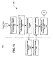
- FIGS. 1A through 1D depict an embodiment of a method for facilitating user connection in accordance with the present invention, which is specifically configured for facilitating such user connection under dynamic host configuration protocol.
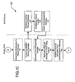
- FIGS. 2A and 2B depict an embodiment of a method for facilitating user connection in accordance with the present invention, which is specifically configured for facilitating such user connection under pint-to-point protocol.
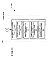
- FIG. 3A depicts an embodiment of a method for facilitating upstream IP forwarding behavior in accordance with the present invention.
- FIG. 3B depicts an embodiment of a method for facilitating upstream IP forwarding behavior in accordance with the present invention.
- FIG. 4A depicts an embodiment of a method for facilitating Proxy ARP functionality between a CPE and an access node in accordance with the present invention.
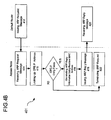
- FIG. 4B depicts an embodiment of a method for facilitating Proxy ARP functionality between a default router and access node in accordance with the present invention.
- Facilitating residential routing functionality in accordance with the present invention includes suitably configuring an access node through which such residential routing functionality is facilitated.
- being suitably configured includes designating a VLAN (virtual local area network) identifier of the service VLAN, enabling Proxy ARP (address resolution protocol) function for the designated VLAN, creating a VLAN specific IP (Internet protocol) forwarding table, creating a respective static route for all upstream traffic to point to a particular service edge router, providing suitable subscriber management, configuring DiffServ (Differentiated Services) marking rules and implementing connection profile configured for subscribed users to create a PVC (permanent virtual connection) from CPE (customer premise equipment) to residential routing delivery point in access node.
- VLAN virtual local area network
- Proxy ARP address resolution protocol
- VLAN specific IP Internet protocol
- DiffServ Differentiated Services
- DHCP dynamic host configuration protocol
- PPP point-to-point protocol
- radius client function is enabled and radius server configuration information are specified.
- a residential routing subscriber is then ready to implement a subscriber connection phase.
- the specific aspects of the subscriber connection phase depend of the type of host communication protocol. DHCP and PPP are two examples of different types of host communication protocols.
- FIGS. 1A through 1D depict an embodiment of a method for facilitating user connection in accordance with the present invention (generally referred to as method 100), which is specifically configured for facilitating such user connection under DHCP.
- the method 100 begins with an operation 102 being performed by customer premise equipment (CPE) for issuing a discovery message to facilitate discovery of a host server (i.e., the DHCP server).
- CPE customer premise equipment
- an operation 106 is performed by the access node for redirecting the discovery message to DHCP relay function of the access node.
- an operation 108 is performed by the access node for adding Option 82 information added to the discovery message, thereby creating a modified discovery message.
- An operation 110 is then performed by the access node for forwarding the modified discovery message for reception by a DHCP server.
- the modified discovery message is forwarded to the DHCP server as, for example, unicast or broadcast).
- Option 82 information enables the DHCP relay function to include information about itself when forwarding client-originated DHCP packets to a DHCP server.
- the DHCP server can use this information to implement IP address or other parameter-assignment policies.
- the access node strips the Option 82 information from downstream traffic (i.e., traffic flowing toward the CPE).
- the DHCP server performs an operation 114 for issuing an offer message for reception by the CPE.
- the offer message issued by the DHCP server serves to offer hosting service by the DHCP server to the CPE and includes corresponding Option 82 information.
- the access node then performs an operation 116 for receiving the offer message, followed by an operation 118 for directing the offer message to the DHCP relay function and an operation 120 for stripping the Option 82 information from the offer message. Stripping the Option 82 information creates a modified offer message.
- the access node performs an operation 122 for forwarding the modified offer message for reception by the CPE.
- the CPE performs an operation 126 for issuing a request message for reception by the DHCP server.
- the request message issued by the DHCP server serves to request hosting service of the DHCP server.
- the access node then performs an operation 128 for receiving the request message, followed by an operation 130 for directing the request message to the DHCP relay function and an operation 132 for adding Option 82 information to the request. Adding the Option 82 information creates a modified request message.
- the access node performs an operation 134 for forwarding the modified request message for reception by the access node.
- the modified request message is forwarded to the DHCP server as, for example, unicast or broadcast).
- the DHCP server performs an operation 138 for initiating requested hosting service, followed by an operation 140 for issuing an acknowledgement message for reception by the CPE.
- the acknowledgement message issued by the DHCP server serves to notify the CPE that the requested hosting service has been initiated and includes corresponding Option 82 information.
- the access node then performs an operation 142 for receiving the acknowledgement message, followed by an operation 144 for directing the acknowledgement message to the DHCP relay function and an operation 146 for stripping the Option 82 information from the acknowledgement message. Stripping the Option 82 information creates a modified acknowledgement message.
- the access node performs an operation 122 for forwarding the modified offer message for reception by the CPE.
- the access node performs an operation 148 for creating a fixed match host entry for the DHCP server and CPE in a downstream forwarding table of the access node and performs an operation 150 for creating a MAC address/IP address association in an ARP table of the access node.
- a MAC address is an identifier that is unique to a local area network card, which is usually programmed into the card during its manufacture.
- the MAC address/IP address association enables proxy-ARP functionality and IP anti-spoofing functionality.
- the access node After stripping the Option 82 information, the access node performs an operation 152 for forwarding the modified acknowledgement for reception by the CPE.
- FIGS. 2A and 2B depict an embodiment of a method for facilitating user connection in accordance with the present invention (generally referred to as method 200), which is specifically configured for facilitating such user connection under PPP.
- the method 200 begins with a CPE and access node jointly performing a process 202 for facilitating PPP NAS (Network Access Server) discovery phase functionality.
- the CPE and the access node jointly performing a process 204 for facilitating PPP LCP (Link Control Protocol) initialization phase functionality.
- the access node and a radius server jointly perform a process 206 for facilitating radius client functionality.
- the CPE and the access node jointly perform a process 208 for facilitating IPCP (Internet Protocol Control Protocol) initialization phase functionality.
- IPCP Internet Protocol Control Protocol
- facilitating PPP NAS (Network Access Server) discovery phase functionality includes an operation 210 for redirecting messages to PPP server functionality of the access node and operation 212 for identifying the access node as the PPP server for the CPE and an operation 214 performing standard PPP NAS behavior and standard PPP messaging.
- facilitating PPP LCP initialization phase functionality includes an operation 216 for redirecting messages to PPP server functionality and an operation 218 for performing standard PPP NAS behavior and standard PPP messaging.
- facilitating radius client functionality includes an operation 219 for providing full NAS functionality, an operation 220 for utilizing radius server functionality for facilitating user authentication and profile information retrieval and an operation 222 for performing standard PPP NAS behavior and standard PPP messaging.
- facilitating IPCP initialization phase functionality includes an operation 224 for redirecting messages to PPP server functionality of the access node, an operation 226 for performing standard PPP NAS behavior and standard PPP messaging, an operation 228 for creating a fixed match host entry for the radius and CPE in a downstream forwarding table of the access node and pan operation 230 for creating a MAC address/IP address association in an ARP table of the access node.
- FIGS. 3A and 3B an embodiment of a method for facilitating upstream IP forwarding behavior in accordance with the present invention (generally referred to as method 300) is depicted in FIG. 3A and an embodiment of a method for facilitating upstream IP forwarding behavior in accordance with the present invention (generally referred to as method 301) is depicted in FIG. 3B .
- the CPE performs an operation 302 for transmitting an IP packet for reception by a designated default router.
- An access node performs an operation 304 for receiving the IP packet and then performs an operation 306 for performing IP anti-spoofing functionality (e.g., an anti-spoofing filter).
- IP anti-spoofing functionality e.g., an anti-spoofing filter
- the access node In response to the IP packet successfully passing the anti-spoofing functionality, the access node performs an operation for forwarding the IP packet to the default router and the default router subsequently performs an operation 310 for receiving the IP packet.
- the IP packet is always forwarded to the default router even if the IP packet belongs to the same IP subnet as source or destination in the downstream forwarding table, thereby precluding a hairpinning situation.
- This default router could be part of a network side VLAN in which case we encapsulate the packet with a PVLAN (Provider VLAN).
- the access node In response to the IP packet not successfully passing the anti-spoofing functionality, the access node performs an operation 312 for dropping the IP packet. If DiffServ marking is configured perform marking rule and schedule IP packet accordingly.
- the residential router functionality includes validating the user packet based on learned 2 or 3 tuple (PVC, MAC address (if available), IP) to prevent IP and MAC spoofing.
- the default router performs an operation 314 for transmitting an IP packet for reception by the CPE.
- the access node performs an operation 316 for receiving the IP packet and then performs an operation 318 for performing CPE-IP address look-up in a corresponding fixed match forwarding table (e.g., the fixed match forwarding table created in associated with FIGS 1 or 2 ).
- the access node performs an operation 320 for forwarding the IP packet to the CPE via a subscriber logical interface and the CPE subsequently performs an operation 322 for receiving the IP packet.
- a logical interface examples include, but are not limited to, ATM PVC, or a DSL port, or a logical port on the GFON, or a VLAN identifier on Ethernet framed DSL technology.
- the logical interface is associated with a PVLAN (private virtual local area network).
- the access node performs an operation 324 for dropping the IP packet. Accordingly, forwarding decisions are based on full host address fixed match (/32) within VLAN context and scheduling of IP packet forwarding is preferably, but not necessarily, based on DiffServ codepoint.
- FIGS. 4A and 4B an embodiment of a method for facilitating Proxy ARP functionality between a CPE and an access node in accordance with the present invention (generally referred to as method 400) is depicted in FIG. 4A and an embodiment of a method for facilitating Proxy ARP functionality between a default router and access node in accordance with the present invention (generally referred to as method 401) is depicted in FIG. 4B .
- the access node In response to the access node performing an operation 404 for receiving the ARP message, the access node performs an operation 406 for generating ARP reply information to the CPE with the access node MAC address.
- the access node generates the ARP reply information using standard Proxy ARP behavior.
- the access node After generating the ARP reply information, the access node performs an operation 408 for issuing an ARP reply message for reception by the CPE and the CPE subsequently performs an operation 410 for receiving the ARP reply message.
- the ARP reply message includes respective portions of the ARP reply information.
- the default router performs an operation 412 for issuing an ARP request message for reception by the access node.
- the access node performs an operation 415 for looking up a CPE-IP address designated in the ARP request message in a Proxy ARP table. If an entry corresponding to the designated CPE-IP address entry exists, the access node performs an operation 416 for generating an ARP reply message to the default router with it's own MAC address, followed by issuing the ARP reply message for reception by the default router.
- the default router then performs an operation 420 for receiving the ARP reply message. If the entry corresponding to the designated CPE-IP address entry does not exists, the access node performs an operation 422 for terminating the ARP request (e.g., taking no further action).
- the method 401 is carried out using standard Proxy ARP behavior.
- Ethernet As an aggregation network technology for broadband access nodes, new network deployment models emerge. Clearly giving the aggregation nature of a access node a deployment model were subscriber traffic for a specific service is aggregated on a per service VLAN is a key requirement.
- Residential routing i.e., residential access routing in accordance with the present invention is a scheme that implements the VLAN per service model while ensuring fundamental security requirements typical for a residential broadband access environment.
- IP CoS Class of Service
- Ethernet CoS can be interpreted equivalently
- conventional residential routing solutions do not readily provide for intelligent drop mechanisms (and hence notification of in-band drop precedence in the data streams) and therefore do not strengthen the case for useful and advantageous IP CoS techniques.
- the basic goal of residential routing functionality in accordance with the present invention is to provide an access solution that can work at Layer 3 level.
- an access node providing residential router functionality in accordance with the present invention provides security features such as limiting the L2 broadcast storms, avoiding security threats such as MAC address spoofing and IP address spoofing. Accordingly, an important factor is that residential router functionality in accordance with the present invention has integral customer-based knowledge that enhances security scalability functionality.
- a method for configuring an access node to provide residential routing functionality comprising: populating a fixed match forwarding table with host entries learned during at least one of authentication of a residential router instance and IP address assignment for the residential router instance; and associating the residential router instance exclusively with a respective virtual local area network (VLAN) identifier;
- VLAN virtual local area network
- the described and/or claimed method further comprising: forwarding downstream traffic dependent upon a host entry designated by said downstream traffic being determined, wherein the host entry is accessed from within the fixed match forwarding table;
- the described and/or claimed method further comprising: forwarding upstream traffic dependent upon a virtual local area network (VLAN) identifier designated by said upstream traffic being determined, wherein the VLAN identifier is dedicated to the residential router instance;
- VLAN virtual local area network
- forwarding upstream traffic includes exclusively forwarding packets received on a VLAN associated with the VLAN identifier to a logical interface configured for being associated with the residential router instance;
- forwarding upstream traffic includes: ignoring a designated destination IP address of an IP packet; and forwarding said IP packet toward a default gateway dependent upon the host entry;
- the described and/or claimed method further comprising: forwarding downstream traffic dependent upon a host entry designated by said downstream traffic being determined; and forwarding upstream traffic dependent upon a virtual local area network (VLAN) identifier designated by said upstream traffic being determined; wherein the host entry is accessed from within the fixed match forwarding table; wherein the VLAN identifier is dedicated to the residential router instance; wherein said forwarding upstream traffic includes exclusively forwarding packets received on a VLAN associated with the VLAN identifier to a logical interface configured for being associated with the residential router instance; and wherein said forwarding upstream traffic includes ignoring a designated destination IP address of an IP packet and forwarding said IP packet toward a default gateway dependent upon the host entry;
- VLAN virtual local area network
- the described and/or claimed method further comprising: providing at least one logical interface associated with the residential router instance, wherein an IP packet received on a VLAN corresponding to the VLAN identifier is limited to being forwarded to one of said logical interfaces;
- the described and/or claimed method further comprising: providing an IP subnet associated with at least the residential router instance;
- the described and/or claimed method further comprising: providing at least one logical interface associated with the residential router instance, wherein an IP packet received on a VLAN corresponding to the VLAN identifier is limited to being forwarded to one of said logical interfaces; providing an IP subnet associated with at least the residential router instance; forwarding downstream traffic dependent upon a host entry designated by said downstream traffic being determined; and forwarding upstream traffic dependent upon a virtual local area network (VLAN) identifier designated by said upstream traffic being determined; wherein the host entry is accessed from within the fixed match forwarding table; wherein the VLAN identifier is dedicated to the residential router instance; wherein said forwarding upstream traffic includes exclusively forwarding packets received on a VLAN associated with the VLAN identifier to a logical interface configured for being associated with the residential router instance; and wherein said forwarding upstream traffic includes ignoring a designated destination IP address of an IP packet and forwarding said IP packet toward a default gateway dependent upon the host entry;
- VLAN virtual local area network
Landscapes
- Engineering & Computer Science (AREA)
- Computer Networks & Wireless Communication (AREA)
- Signal Processing (AREA)
- Computer Hardware Design (AREA)
- Computer Security & Cryptography (AREA)
- Computing Systems (AREA)
- General Engineering & Computer Science (AREA)
- Data Exchanges In Wide-Area Networks (AREA)
Description
- The disclosures made herein relate generally to data communication within a computer network and, more particularly, to methods and systems configured for facilitating residential broadband service.
-
US Patent Application Publication 2003/0214955 Al discloses a method comprising the features of the preamble of claim 1. A network connection apparatus for communicating between a network device located in a first private network and a second private network located outside the first private network is described. In order to provide a communication link between both networks a virtual private network tunnel is established. -
US Patent Application Publication 2003/0026273 Al also discloses a method and a network for providing virtual private network tunnels. - US patent application
US 2003/0165140 relates to distributing in virtual local area networks. - Broadband access to the Internet offers significantly increased speed and availability when compared to dial-up (i.e., or narrowband) access. Broadband is a provided via a dedicated connection, thus making it a relatively always-on connection.
- Generally, a broadband access connection provides bi-directional network connection speeds of at least about 200,000 bits per second (bps). By contrast, a relatively fast dial-up access connection provides maximum bi-directional network connection speeds of about 56,000 bps. However, the connection speed of a typical dial-up access connection is often much slower because of imperfections on the line.
- The speed and availability of broadband has contributed to the rapidly increasing demand for broadband by residential subscribers. Such service is referred to herein as residential broadband. This speed and availability enables residential broadband to support not only data service, but also video services and home entertainment services such as, for example, virtual reality gaming, downloadable music and video, multimedia presentations, VoIP (Voice over IP) and other services that require relatively a high-speed connection to provide a suitable quality-of-service.
- Due in part to increased demands for and expectations of residential broadband, the landscape for residential broadband service is changing. New types of services will require multiple classes of service levels to provide differentiated treatment for high-quality services. Aggregation networks for residential broadband traffic will optimally move from ATM (asynchronous transfer mode) based networks to Ethernet-based aggregation networks. Additionally, new services might introduce alternative subscriber management and auto-configuration requirements.
- The transition to an Ethernet aggregation network will have a particularly significant impact on the way services are delivered over the aggregation network. In such a conventional Ethernet aggregation network, access nodes with Ethernet-based network interfaces can either be restricted to operate only at the Ethernet layer, a pure layer-2, or work as full router, which significantly limits the ability to offer IP (Internet Protocol) forwarding flexibility and security in the access node while retaining the usage of a layer-2 aggregation network. Accordingly, the use of a broadcast medium (e.g., Ethernet) in combination with a point-to-point access technology for mass deployment poses a variety of security and scalability challenges. These challenges include, are not be limited to, suitable implementation of isolating a service subscriber for traffic forwarding, isolating the service subscriber for security reasons and isolating the service subscriber for billing.
- Standard routing with proxy ARP (Address Resolution Protocol) in the access node represents a conventional approach for implementing residential broadband service with an Ethernet based aggregation network. Such standard routing with proxy ARP is accomplished by implementing Ethernet ARP under RFC (Request For Comments) 1027 via subnet gateways to permit hosts on the connected subnets to communicate without being aware of the existence of subnets (i.e., using Proxy ARP). Accordingly, such proxy ARP allows a network element such as a router, which is physically located on one network, appear to be logically part of a different physical network connected to the same host (e.g., router). Typically, proxy ARP allows a machine with a public IP address on a private network to be hid behind a router, and still have the machine appear to be on the public network "in front of" the router. The router proxys ARP requests and all network traffic to and from the hidden machine to make this fiction possible.
- However, there are a number of potential problems with the use of proxy ARP. These problems include, but are not limited to, difficulties in protecting against attacks, requiring undesirable amounts of processing power, having a relatively complex configuration and making it relatively difficult to block direct user-to-user communication. Additionally, constraints on IP address allocation schemes often result in inefficient use of address space and complex configuration.
- Therefore, an approach for implementing residential broadband service with an Ethernet-based aggregation network in a manner that at least partially overcomes shortcomings associated with conventional approaches for implementing residential broadband service with an Ethernet-based aggregation network would be advantageous, useful and novel.
- The invention is defined by the independent claims 1 and 6.
- Embodiments of the present invention enable residential routing functionality to be facilitated in a manner that overcomes shortcomings associated with conventional approaches for facilitating residential routing functionality. More specifically, embodiments of systems and methods in accordance with the present invention provide for implementation of a residential broadband service with an Ethernet-based aggregation network where the access node is the first network element treating the traffic at the IP layer and implementation of a DiffServ (differentiated services) framework compliant behavior. The major differences of residential routing in accordance with the present invention as compared to a traditional router with proxy ARP include, but are not limited to, direction aware behavior where upstream and downstream forwarding models are completely different, a utilized forwarding table is defined in the context of a VLAN, and host addresses in the utilized forwarding table are configured through an authentication/auto-configuration process and not learned from the data flow. The advantages of these systems and methods include, but are not limited to, improved security (e.g., IP anti-spoofing, automatic blocking of direct user to user communication, etc), intuitive configuration, flexible IP address allocation and wholesale service model accommodation.
- Residential routing functionality in accordance with the present invention provides a solution that advantageously addresses the changing landscape of residential broadband service delivery. Examples of such changes include, but are not limited to, new services will require multiple class of service levels to provide differentiated treatment for high quality services, aggregation networks for residential broadband traffic will move from ATM based networks to Ethernet based networks and new service might introduce alternative subscriber management and auto-configuration requirements. Conventional approaches for providing residential routing functionality are limited in their ability to address such changes in the landscape of residential broadband service delivery. Accordingly, residential routing functionality in accordance with the present invention is advantageous with respect to conventional approaches for providing residential routing functionality.
- The move to an Ethernet aggregation network will especially impact the way services are delivered over the aggregation network. Conventionally, access nodes with Ethernet based network interfaces can either be restricted to operate only at the Ethernet layer or as a pure layer 2 or work as full router. The use of a broadcast medium (e.g., Ethernet) in combination with a point-to-point access technology for mass deployment poses a variety of security and scalability challenges. These challenges include, but are not limited to, facilitating isolation of an end customer for traffic forwarding, facilitating isolation of an end customer for security reasons and facilitating isolation of an end customer for billing. Advantageously, residential access bridging and residential access routing (i.e., residential routing) in accordance with the present invention address these challenges through a Layer 2 and IP forwarding mode respectfully by including specific behavior in both the control and forwarding plane without impacting standard protocol behavior. To this end, one object of residential routing functionality in accordance with the present invention is to offer IP forwarding flexibility and security in the access node while retaining the usage of a layer 2-aggregation network.
- Residential routing functionality in accordance with the present invention provides for an IP forwarding scheme for a residential broadband service using a VLAN (virtual local area network) aware Ethernet aggregation network. This functionality contributes to a number of beneficial attributes. Examples of such beneficial attributes include, but are not limited to, full flexibility in subscriber management and auto-configuration models, support for PPP and DHCP based models, full flexibility in user traffic encapsulation schemes, support for PPP encapsulation (e.g., PPPoE, PPPoA), support for RFC 2684 bridged and routed encapsulation, IP anti spoofing operation, DiffServ per hop behavior, compatibility with overlapping IP address spaces, support for IP address allocation per service I.S.O. per Access Node, hairpin blocking operation and not requiring IP - Subnet address range per residential router.
- In one embodiment of the present invention, an access node configured for facilitating residential routing functionality comprises a virtual local area network (VLAN) identifier exclusively associated with an instance of a residential router and a fixed match forwarding table exclusively populated with host entries learned during residential router authentication or IP address assignment.
- In another embodiment of the present invention, a method for facilitating residential routing functionality comprises forwarding upstream traffic dependent upon a virtual local area network (VLAN) identifier designated by the upstream traffic being determined and forwarding downstream traffic dependent upon a host entry designated by the downstream traffic being determined. The VLAN identifier is dedicated to an instance of a residential router and the host entry is provided in a fixed match forwarding table.
- In another embodiment of the present invention, a method for configuring an access node to provide residential routing functionality comprises populating a fixed match forwarding table with host entries learned during authentication of or IP address assignment for a residential router instance and then associating the residential router instance exclusively with a respective virtual local area network (VLAN) identifier.
- Turning now to specific aspects of the present invention, in at least one embodiment, upstream traffic is forwarded dependent upon the VLAN identifier.
- In at least one embodiment of the inventive disclosures made herein, downstream traffic is forwarded dependent upon one of the host entries of the fixed match forwarding table.
- In at least one embodiment of the inventive disclosures made herein, at least one logical interface is provided and is configured for being associated with the instance of the residential router, wherein an IP packet received on a VLAN corresponding to the VLAN identifier is limited to being forwarded to one of the logical interfaces.
- In at least one embodiment of the inventive disclosures made herein, an IP subnet associated with at least the instance of the residential router is provided.
- In at least one embodiment of the inventive disclosures made herein, at least one of the forwarding upstream traffic and the forwarding downstream traffic includes precluding VLAN-to-VLAN communication.
- In at least one embodiment of the inventive disclosures made herein, at least one of the forwarding upstream traffic and the forwarding downstream traffic includes exclusively forwarding packets received on a VLAN associated with the VLAN identifier to a logical interface configured for being associated with the instance of a residential router.
- In at least one embodiment of the inventive disclosures made herein, an operation is performed for creating a VLAN-specific IP forwarding table, wherein the VLAN identifier and the host entries are accessible from the VLAN-specific IP forwarding table.
- In at least one embodiment of the inventive disclosures made herein, forwarding the upstream traffic includes ignoring a designated destination IP address of an IP packet and forwarding the IP packet toward a default gateway dependent upon the host entry.
- These and other objects and embodiments of the inventive disclosures made herein will become readily apparent upon further review of the following specification and associated drawings.
-
FIGS. 1A through 1D depict an embodiment of a method for facilitating user connection in accordance with the present invention, which is specifically configured for facilitating such user connection under dynamic host configuration protocol. -
FIGS. 2A and2B depict an embodiment of a method for facilitating user connection in accordance with the present invention, which is specifically configured for facilitating such user connection under pint-to-point protocol. -
FIG. 3A depicts an embodiment of a method for facilitating upstream IP forwarding behavior in accordance with the present invention. -
FIG. 3B depicts an embodiment of a method for facilitating upstream IP forwarding behavior in accordance with the present invention. -
FIG. 4A depicts an embodiment of a method for facilitating Proxy ARP functionality between a CPE and an access node in accordance with the present invention. -
FIG. 4B depicts an embodiment of a method for facilitating Proxy ARP functionality between a default router and access node in accordance with the present invention. - Facilitating residential routing functionality in accordance with the present invention includes suitably configuring an access node through which such residential routing functionality is facilitated. In one embodiment, being suitably configured includes designating a VLAN (virtual local area network) identifier of the service VLAN, enabling Proxy ARP (address resolution protocol) function for the designated VLAN, creating a VLAN specific IP (Internet protocol) forwarding table, creating a respective static route for all upstream traffic to point to a particular service edge router, providing suitable subscriber management, configuring DiffServ (Differentiated Services) marking rules and implementing connection profile configured for subscribed users to create a PVC (permanent virtual connection) from CPE (customer premise equipment) to residential routing delivery point in access node. Where residential routing functionality is being set-up to allow for user auto-configuration with DHCP (dynamic host configuration protocol), a DHCP server address is provided for and DHCP relay function with
option 82 is enabled. Where residential routing functionality is being set-up to allow for users to connect with PPP (point-to-point protocol), PPP termination function and radius client function are enabled and radius server configuration information are specified. - With the access node suitably configured, a residential routing subscriber is then ready to implement a subscriber connection phase. The specific aspects of the subscriber connection phase depend of the type of host communication protocol. DHCP and PPP are two examples of different types of host communication protocols.
-
FIGS. 1A through 1D depict an embodiment of a method for facilitating user connection in accordance with the present invention (generally referred to as method 100), which is specifically configured for facilitating such user connection under DHCP. Themethod 100 begins with anoperation 102 being performed by customer premise equipment (CPE) for issuing a discovery message to facilitate discovery of a host server (i.e., the DHCP server). In response to an access node performing anoperation 104 for receiving the discovery message, an operation 106 is performed by the access node for redirecting the discovery message to DHCP relay function of the access node. Next, anoperation 108 is performed by the access node for addingOption 82 information added to the discovery message, thereby creating a modified discovery message. Anoperation 110 is then performed by the access node for forwarding the modified discovery message for reception by a DHCP server. The modified discovery message is forwarded to the DHCP server as, for example, unicast or broadcast). -
Option 82 information enables the DHCP relay function to include information about itself when forwarding client-originated DHCP packets to a DHCP server. The DHCP server can use this information to implement IP address or other parameter-assignment policies. In the depicted embodiment, the access node strips theOption 82 information from downstream traffic (i.e., traffic flowing toward the CPE). - In response to the DHCP server performing an
operation 112 for receiving the modified discovery message, the DHCP server performs anoperation 114 for issuing an offer message for reception by the CPE. The offer message issued by the DHCP server serves to offer hosting service by the DHCP server to the CPE and includes correspondingOption 82 information. The access node then performs anoperation 116 for receiving the offer message, followed by anoperation 118 for directing the offer message to the DHCP relay function and anoperation 120 for stripping theOption 82 information from the offer message. Stripping theOption 82 information creates a modified offer message. The access node performs anoperation 122 for forwarding the modified offer message for reception by the CPE. - In response to the CPE performing an
operation 124 for receiving the modified offer message, the CPE performs anoperation 126 for issuing a request message for reception by the DHCP server. The request message issued by the DHCP server serves to request hosting service of the DHCP server. The access node then performs anoperation 128 for receiving the request message, followed by anoperation 130 for directing the request message to the DHCP relay function and anoperation 132 for addingOption 82 information to the request. Adding theOption 82 information creates a modified request message. The access node performs anoperation 134 for forwarding the modified request message for reception by the access node. The modified request message is forwarded to the DHCP server as, for example, unicast or broadcast). - In response to the DHCP server performing an
operation 136 for receiving the modified request message, the DHCP server performs anoperation 138 for initiating requested hosting service, followed by anoperation 140 for issuing an acknowledgement message for reception by the CPE. The acknowledgement message issued by the DHCP server serves to notify the CPE that the requested hosting service has been initiated and includes correspondingOption 82 information. The access node then performs anoperation 142 for receiving the acknowledgement message, followed by anoperation 144 for directing the acknowledgement message to the DHCP relay function and an operation 146 for stripping theOption 82 information from the acknowledgement message. Stripping theOption 82 information creates a modified acknowledgement message. The access node performs anoperation 122 for forwarding the modified offer message for reception by the CPE. The access node performs anoperation 148 for creating a fixed match host entry for the DHCP server and CPE in a downstream forwarding table of the access node and performs anoperation 150 for creating a MAC address/IP address association in an ARP table of the access node. A MAC address is an identifier that is unique to a local area network card, which is usually programmed into the card during its manufacture. The MAC address/IP address association enables proxy-ARP functionality and IP anti-spoofing functionality. After stripping theOption 82 information, the access node performs anoperation 152 for forwarding the modified acknowledgement for reception by the CPE. -
FIGS. 2A and2B depict an embodiment of a method for facilitating user connection in accordance with the present invention (generally referred to as method 200), which is specifically configured for facilitating such user connection under PPP. Themethod 200 begins with a CPE and access node jointly performing aprocess 202 for facilitating PPP NAS (Network Access Server) discovery phase functionality. In response to facilitating the PPP NAS discovery phase functionality, the CPE and the access node jointly performing aprocess 204 for facilitating PPP LCP (Link Control Protocol) initialization phase functionality. In conjunction with the PPP LCP initialization phase functionality being facilitated, the access node and a radius server jointly perform aprocess 206 for facilitating radius client functionality. After performing the processes for facilitating PPP LCP initialization phase functionality and the radius client functionality, the CPE and the access node jointly perform aprocess 208 for facilitating IPCP (Internet Protocol Control Protocol) initialization phase functionality. - In one embodiment of the present invention, facilitating PPP NAS (Network Access Server) discovery phase functionality includes an
operation 210 for redirecting messages to PPP server functionality of the access node andoperation 212 for identifying the access node as the PPP server for the CPE and anoperation 214 performing standard PPP NAS behavior and standard PPP messaging. In one embodiment of the present invention, facilitating PPP LCP initialization phase functionality includes anoperation 216 for redirecting messages to PPP server functionality and anoperation 218 for performing standard PPP NAS behavior and standard PPP messaging. In one embodiment of the present invention, facilitating radius client functionality includes anoperation 219 for providing full NAS functionality, anoperation 220 for utilizing radius server functionality for facilitating user authentication and profile information retrieval and anoperation 222 for performing standard PPP NAS behavior and standard PPP messaging. In one embodiment of the present invention, facilitating IPCP initialization phase functionality includes anoperation 224 for redirecting messages to PPP server functionality of the access node, anoperation 226 for performing standard PPP NAS behavior and standard PPP messaging, anoperation 228 for creating a fixed match host entry for the radius and CPE in a downstream forwarding table of the access node andpan operation 230 for creating a MAC address/IP address association in an ARP table of the access node. - Referring to
FIGS. 3A and3B , an embodiment of a method for facilitating upstream IP forwarding behavior in accordance with the present invention (generally referred to as method 300) is depicted inFIG. 3A and an embodiment of a method for facilitating upstream IP forwarding behavior in accordance with the present invention (generally referred to as method 301) is depicted inFIG. 3B . Referring first to themethod 300 for facilitating upstream IP forwarding behavior (FIG. 3A ), the CPE performs anoperation 302 for transmitting an IP packet for reception by a designated default router. An access node performs anoperation 304 for receiving the IP packet and then performs anoperation 306 for performing IP anti-spoofing functionality (e.g., an anti-spoofing filter). In response to the IP packet successfully passing the anti-spoofing functionality, the access node performs an operation for forwarding the IP packet to the default router and the default router subsequently performs anoperation 310 for receiving the IP packet. Where an IP packet successfully passing the anti-spoofing functionality, the IP packet is always forwarded to the default router even if the IP packet belongs to the same IP subnet as source or destination in the downstream forwarding table, thereby precluding a hairpinning situation. This default router could be part of a network side VLAN in which case we encapsulate the packet with a PVLAN (Provider VLAN). In response to the IP packet not successfully passing the anti-spoofing functionality, the access node performs anoperation 312 for dropping the IP packet. If DiffServ marking is configured perform marking rule and schedule IP packet accordingly. Additionally, the residential router functionality includes validating the user packet based on learned 2 or 3 tuple (PVC, MAC address (if available), IP) to prevent IP and MAC spoofing. - Referring now to the
method 301 for facilitating downstream IP forwarding behavior (FIG. 3B ), the default router performs anoperation 314 for transmitting an IP packet for reception by the CPE. The access node performs anoperation 316 for receiving the IP packet and then performs anoperation 318 for performing CPE-IP address look-up in a corresponding fixed match forwarding table (e.g., the fixed match forwarding table created in associated withFIGS 1 or2 ). In response to the CPE-IP address existing in the fixed match forwarding table, the access node performs an operation 320 for forwarding the IP packet to the CPE via a subscriber logical interface and the CPE subsequently performs anoperation 322 for receiving the IP packet. Examples of such a logical interface include, but are not limited to, ATM PVC, or a DSL port, or a logical port on the GFON, or a VLAN identifier on Ethernet framed DSL technology. In one embodiment, the logical interface is associated with a PVLAN (private virtual local area network). In response to the CPE-IP address does not existing in the fixed match forwarding table, the access node performs anoperation 324 for dropping the IP packet. Accordingly, forwarding decisions are based on full host address fixed match (/32) within VLAN context and scheduling of IP packet forwarding is preferably, but not necessarily, based on DiffServ codepoint. - Referring to
FIGS. 4A and4B , an embodiment of a method for facilitating Proxy ARP functionality between a CPE and an access node in accordance with the present invention (generally referred to as method 400) is depicted inFIG. 4A and an embodiment of a method for facilitating Proxy ARP functionality between a default router and access node in accordance with the present invention (generally referred to as method 401) is depicted inFIG. 4B . Referring first to themethod 400 for facilitating Proxy ARP functionality between the CPE and the access node (FIG. 4A ), anoperation 402 for issuing an ARP request message for reception by the access node. In response to the access node performing anoperation 404 for receiving the ARP message, the access node performs an operation 406 for generating ARP reply information to the CPE with the access node MAC address. The access node generates the ARP reply information using standard Proxy ARP behavior. After generating the ARP reply information, the access node performs anoperation 408 for issuing an ARP reply message for reception by the CPE and the CPE subsequently performs anoperation 410 for receiving the ARP reply message. The ARP reply message includes respective portions of the ARP reply information. - Referring now to the
method 401 for facilitating Proxy ARP functionality between a default router and access node (FIG. 4B ), the default router performs anoperation 412 for issuing an ARP request message for reception by the access node. In response to the access node performing anoperation 414 for receiving the ARP request message, the access node performs anoperation 415 for looking up a CPE-IP address designated in the ARP request message in a Proxy ARP table. If an entry corresponding to the designated CPE-IP address entry exists, the access node performs anoperation 416 for generating an ARP reply message to the default router with it's own MAC address, followed by issuing the ARP reply message for reception by the default router. The default router then performs anoperation 420 for receiving the ARP reply message. If the entry corresponding to the designated CPE-IP address entry does not exists, the access node performs anoperation 422 for terminating the ARP request (e.g., taking no further action). Themethod 401 is carried out using standard Proxy ARP behavior. - With the introduction of Ethernet as an aggregation network technology for broadband access nodes, new network deployment models emerge. Clearly giving the aggregation nature of a access node a deployment model were subscriber traffic for a specific service is aggregated on a per service VLAN is a key requirement. Residential routing (i.e., residential access routing) in accordance with the present invention is a scheme that implements the VLAN per service model while ensuring fundamental security requirements typical for a residential broadband access environment.
- In view of behavior associated with conventional residential access bridging that is provided in the access devices such as a DSLAM (Digital Subscriber Line Access Mutliplexer) or an OLT (Optical Line Terminal), there are a number of limitations with conventional access solutions that use layer 2 bridging, which are overcome by residential routing facilitated in accordance with the present invention. One example of such a limitation is that conventional access solutions do not reduce the number of MAC addresses present in the Ethernet network, which can pose significant problems if an associated FTTU (Fiber-To-The-User) or DSLAM based network grows beyond a certain limit. Another example of such a limitation is that conventional access solutions are limited in their ability to implement intelligent RGW (Residential Gateway) with IP address based service selection. Still another example of such a limitation is that, while IP CoS (Class of Service) and Ethernet CoS can be interpreted equivalently, conventional residential routing solutions do not readily provide for intelligent drop mechanisms (and hence notification of in-band drop precedence in the data streams) and therefore do not strengthen the case for useful and advantageous IP CoS techniques.
- The basic goal of residential routing functionality in accordance with the present invention is to provide an access solution that can work at Layer 3 level. By being the first layer 3 aware device on the customer side, an access node providing residential router functionality in accordance with the present invention provides security features such as limiting the L2 broadcast storms, avoiding security threats such as MAC address spoofing and IP address spoofing. Accordingly, an important factor is that residential router functionality in accordance with the present invention has integral customer-based knowledge that enhances security scalability functionality.
- The following method as well as the following method steps, separately or in any combination, may also constitute advantageous embodiments of the described and/or claimed method/s:
- A method for configuring an access node to provide residential routing functionality, comprising: populating a fixed match forwarding table with host entries learned during at least one of authentication of a residential router instance and IP address assignment for the residential router instance; and associating the residential router instance exclusively with a respective virtual local area network (VLAN) identifier;
- The described and/or claimed method, further comprising: forwarding downstream traffic dependent upon a host entry designated by said downstream traffic being determined, wherein the host entry is accessed from within the fixed match forwarding table;
- The described and/or claimed method, further comprising: forwarding upstream traffic dependent upon a virtual local area network (VLAN) identifier designated by said upstream traffic being determined, wherein the VLAN identifier is dedicated to the residential router instance;
- The described and/or claimed method wherein said forwarding upstream traffic includes exclusively forwarding packets received on a VLAN associated with the VLAN identifier to a logical interface configured for being associated with the residential router instance;
- The described and/or claimed method wherein said forwarding upstream traffic includes: ignoring a designated destination IP address of an IP packet; and forwarding said IP packet toward a default gateway dependent upon the host entry;
- The described and/or claimed method, further comprising: forwarding downstream traffic dependent upon a host entry designated by said downstream traffic being determined; and forwarding upstream traffic dependent upon a virtual local area network (VLAN) identifier designated by said upstream traffic being determined; wherein the host entry is accessed from within the fixed match forwarding table; wherein the VLAN identifier is dedicated to the residential router instance; wherein said forwarding upstream traffic includes exclusively forwarding packets received on a VLAN associated with the VLAN identifier to a logical interface configured for being associated with the residential router instance; and wherein said forwarding upstream traffic includes ignoring a designated destination IP address of an IP packet and forwarding said IP packet toward a default gateway dependent upon the host entry;
- The described and/or claimed method, further comprising: providing at least one logical interface associated with the residential router instance, wherein an IP packet received on a VLAN corresponding to the VLAN identifier is limited to being forwarded to one of said logical interfaces;
- The described and/or claimed method, further comprising: providing an IP subnet associated with at least the residential router instance;
- The described and/or claimed method, further comprising: providing at least one logical interface associated with the residential router instance, wherein an IP packet received on a VLAN corresponding to the VLAN identifier is limited to being forwarded to one of said logical interfaces; providing an IP subnet associated with at least the residential router instance; forwarding downstream traffic dependent upon a host entry designated by said downstream traffic being determined; and forwarding upstream traffic dependent upon a virtual local area network (VLAN) identifier designated by said upstream traffic being determined; wherein the host entry is accessed from within the fixed match forwarding table; wherein the VLAN identifier is dedicated to the residential router instance; wherein said forwarding upstream traffic includes exclusively forwarding packets received on a VLAN associated with the VLAN identifier to a logical interface configured for being associated with the residential router instance; and wherein said forwarding upstream traffic includes ignoring a designated destination IP address of an IP packet and forwarding said IP packet toward a default gateway dependent upon the host entry;
- The described and/or claimed method/s wherein at least one of said forwarding upstream traffic and said forwarding downstream traffic includes precluding VLAN-to-VLAN communication.
- In the preceding detailed description, reference has been made to the accompanying drawings that form a part hereof, and in which are shown by way of illustration specific embodiments in which the invention may be practiced. These embodiments, and certain variants thereof, have been described in sufficient detail to enable those skilled in the art to practice the invention. It is to be understood that other suitable embodiments may be utilized and that logical, mechanical and electrical changes may be made without departing from the spirit or scope of the invention. For example, functional blocks shown in the figures could be further combined or divided in any manner without departing from the spirit or scope of the invention. To avoid unnecessary detail, the description omits certain information known to those skilled in the art. The preceding detailed description is, therefore, not intended to be limited to the specific forms set forth herein, but on the contrary, it is intended to cover such alternatives, modifications, and equivalents, as can be reasonably included within the spirit and scope of the appended claims.
Claims (6)
- A method for providing residential routing functionality, comprising the steps of forwarding upstream and downstream traffic;
characterized in that- virtual local area networks are provided;- wherein operating a virtual local area network includes the steps of:- associating a residential router instance exclusively with a respective virtual local area network identifier;- populating a fixed match forwarding table with host entries learned during at least one of authentication of a residential router instance and IP address assignment for the residential router instance;- forwarding upstream traffic dependent upon said virtual local area network identifier designated by said upstream traffic being determined, wherein the virtual local area network identifier is dedicated to said instance of the residential router; and- forwarding downstream traffic dependent upon the host entry designated by said downstream traffic being determined, wherein the host entry is provided in said fixed match forwarding table. - The method of claim 1, wherein at least one of said forwarding upstream traffic and said forwarding downstream traffic includes precluding VLAN-to-VLAN communication.
- The method of any of the preceding claims, wherein at least one of said forwarding upstream traffic and said forwarding downstream traffic includes exclusively forwarding packets received on the virtual local area network associated with the virtual local area network identifier to a logical interface configured for being associated with the instance of the residential router.
- The method of any of the preceding claims, further comprising:creating a VLAN-specific IP forwarding table, wherein the VLAN identifier and said host entries are accessible from the VLAN-specific IP forwarding table.
- The method of any of the preceding claims wherein forwarding said upstream traffic includes:- ignoring a designated destination IP address of an IP packet; and- forwarding said IP packet toward a default gateway dependent upon the host entry.
- An access node configured for providing residential routing functionality, including forwarding upstream and downstream traffic;
characterized by- a virtual local area network identifier exclusively associated with an instance of a residential router, wherein an IP subnet is associated with at least the instance of the residential router;- a fixed match forwarding table exclusively populated with host entries learned during at least one of residential router authentication and or IP address assignment; and- at least one logical interface configured for being associated with the instance of the residential router;- wherein an IP packet received on a virtual local area network corresponding to the virtual local area network identifier is limited to being forwarded to one of said logical interfaces;- wherein upstream traffic is forwarded dependent upon the virtual local area network identifier; and- wherein downstream traffic is forwarded dependent upon one of said host entries of the fixed match forwarding table.
Applications Claiming Priority (4)
| Application Number | Priority Date | Filing Date | Title |
|---|---|---|---|
| US56281704P | 2004-04-16 | 2004-04-16 | |
| US562817P | 2004-04-16 | ||
| US63699 | 2005-02-11 | ||
| US11/063,699 US7801123B2 (en) | 2004-04-16 | 2005-02-22 | Method and system configured for facilitating residential broadband service |
Publications (3)
| Publication Number | Publication Date |
|---|---|
| EP1589705A2 EP1589705A2 (en) | 2005-10-26 |
| EP1589705A3 EP1589705A3 (en) | 2006-06-14 |
| EP1589705B1 true EP1589705B1 (en) | 2015-03-18 |
Family
ID=34934669
Family Applications (1)
| Application Number | Title | Priority Date | Filing Date |
|---|---|---|---|
| EP05007151.3A Not-in-force EP1589705B1 (en) | 2004-04-16 | 2005-04-01 | Method and system configured for facilitating residential broadband service |
Country Status (2)
| Country | Link |
|---|---|
| US (1) | US7801123B2 (en) |
| EP (1) | EP1589705B1 (en) |
Families Citing this family (23)
| Publication number | Priority date | Publication date | Assignee | Title |
|---|---|---|---|---|
| US7535926B1 (en) | 2005-01-07 | 2009-05-19 | Juniper Networks, Inc. | Dynamic interface configuration for supporting multiple versions of a communication protocol |
| US7539205B1 (en) * | 2005-01-07 | 2009-05-26 | Juniper Networks, Inc. | Service-specific logical interfaces for providing VPN customers access to external multicast content |
| US7889754B2 (en) * | 2005-07-12 | 2011-02-15 | Cisco Technology, Inc. | Address resolution mechanism for ethernet maintenance endpoints |
| US7606232B1 (en) | 2005-11-09 | 2009-10-20 | Juniper Networks, Inc. | Dynamic virtual local area network (VLAN) interface configuration |
| US7492766B2 (en) * | 2006-02-22 | 2009-02-17 | Juniper Networks, Inc. | Dynamic building of VLAN interfaces based on subscriber information strings |
| US7808994B1 (en) | 2006-02-22 | 2010-10-05 | Juniper Networks, Inc. | Forwarding traffic to VLAN interfaces built based on subscriber information strings |
| US8745253B2 (en) * | 2006-03-08 | 2014-06-03 | Alcatel Lucent | Triggering DHCP actions from IEEE 802.1x state changes |
| US8306529B2 (en) * | 2006-09-15 | 2012-11-06 | Alcatel Lucent | Method and apparatus for concurrent registration of voice and data subscribers |
| US7821941B2 (en) * | 2006-11-03 | 2010-10-26 | Cisco Technology, Inc. | Automatically controlling operation of a BRAS device based on encapsulation information |
| US8363660B2 (en) | 2006-11-09 | 2013-01-29 | Telefonaktiebolaget Lm Ericsson (Publ) | Arrangement and method relating to identification of hardware units |
| US8751625B2 (en) * | 2006-12-04 | 2014-06-10 | Canon Kabushiki Kaisha | Notification apparatus and notification method |
| CN101355474B (en) * | 2007-07-25 | 2010-09-08 | 华为技术有限公司 | Method and equipment for requesting and distributing connection point address |
| EP2274897B1 (en) * | 2007-11-26 | 2012-01-11 | Telefonaktiebolaget LM Ericsson (publ) | Technique for address resolution in a data transmission network |
| EP2073506B1 (en) * | 2007-12-21 | 2017-05-03 | Alcatel Lucent | Method for resolving a logical user address in an aggregation network |
| US8953601B2 (en) * | 2008-05-13 | 2015-02-10 | Futurewei Technologies, Inc. | Internet protocol version six (IPv6) addressing and packet filtering in broadband networks |
| CN101616062B (en) * | 2008-06-26 | 2012-07-04 | 中兴通讯股份有限公司 | Method for realizing IP transmitting |
| WO2010141450A2 (en) * | 2009-06-01 | 2010-12-09 | The Regents Of The University Of Michigan | Method for extending the use of single ipv4 addresses to multiple network end-hosts |
| US8599768B2 (en) * | 2009-08-24 | 2013-12-03 | Intel Corporation | Distributing group size indications to mobile stations |
| CN103546374B (en) | 2012-07-10 | 2016-08-03 | 杭州华三通信技术有限公司 | A kind of method and apparatus E-Packeted in edge double layer network |
| US9819578B2 (en) | 2013-08-26 | 2017-11-14 | Nec Corporation | Communication device and method in a communication system, and device and method for communication path control |
| JP6414065B2 (en) * | 2013-08-26 | 2018-10-31 | 日本電気株式会社 | Communication apparatus and method in communication system, communication path control apparatus and method |
| CN111385132B (en) * | 2018-12-29 | 2022-12-06 | 中兴通讯股份有限公司 | Route configuration method, route updating method and device |
| CN111953663B (en) * | 2020-07-27 | 2022-10-21 | 新华三技术有限公司 | Method and equipment for controlling user to authenticate |
Family Cites Families (5)
| Publication number | Priority date | Publication date | Assignee | Title |
|---|---|---|---|---|
| US6829242B2 (en) | 1998-06-30 | 2004-12-07 | Cisco Technology, Inc. | Method and apparatus for associating PVC identifiers with domain names of home gateways |
| JP4183379B2 (en) * | 2000-11-27 | 2008-11-19 | 富士通株式会社 | Network and edge router |
| KR100485769B1 (en) | 2002-05-14 | 2005-04-28 | 삼성전자주식회사 | Apparatus and method for offering connection between network devices located in different home networks |
| US7680086B2 (en) * | 2002-09-09 | 2010-03-16 | Siemens Canada Limited | Wireless local area network with clients having extended freedom of movement |
| US7234163B1 (en) * | 2002-09-16 | 2007-06-19 | Cisco Technology, Inc. | Method and apparatus for preventing spoofing of network addresses |
-
2005
- 2005-02-22 US US11/063,699 patent/US7801123B2/en not_active Expired - Fee Related
- 2005-04-01 EP EP05007151.3A patent/EP1589705B1/en not_active Not-in-force
Also Published As
| Publication number | Publication date |
|---|---|
| EP1589705A3 (en) | 2006-06-14 |
| US7801123B2 (en) | 2010-09-21 |
| EP1589705A2 (en) | 2005-10-26 |
| US20050232228A1 (en) | 2005-10-20 |
Similar Documents
| Publication | Publication Date | Title |
|---|---|---|
| EP1589705B1 (en) | Method and system configured for facilitating residential broadband service | |
| US7469298B2 (en) | Method and system for enabling layer 2 transmission of IP data frame between user terminal and service provider | |
| US8635314B2 (en) | Use of IPv6 in access networks | |
| US8121126B1 (en) | Layer two (L2) network access node having data plane MPLS | |
| US8036237B2 (en) | System and method for transparent virtual routing | |
| US7489700B2 (en) | Virtual access router | |
| KR101063080B1 (en) | How to provide Ethernet DSL access multiplexer and dynamic service selection and end-user configuration | |
| US8085791B1 (en) | Using layer two control protocol (L2CP) for data plane MPLS within an L2 network access node | |
| US8451833B2 (en) | System and method for transparent virtual routing | |
| US20150172994A1 (en) | Dynamic vlans in wireless networks | |
| AU2010255430B2 (en) | Dynamically configuring attributes of a parent circuit on a network element | |
| US20080285569A1 (en) | Device for Session-Based Packet Switching | |
| KR100424650B1 (en) | PPPoA SPOOFING IN POINT-TO-POINT PROTOCOL OVER ATM USING AN xDSL MODEM | |
| WO2008023360A2 (en) | Point-to-multipoint functionality in a bridged network | |
| WO2007124679A1 (en) | Method and system of network communication | |
| WO2011147342A1 (en) | Method, equipment and system for exchanging routing information | |
| Hernandez-Valencia | Architectures for broadband residential IP services over CATV networks | |
| Cisco | Configuring NI-2 IP Services | |
| Cisco | Glossary | |
| Cisco | Glossary | |
| Cisco | Glossary | |
| EP1981217A1 (en) | Method for forwarding data packets in an access network and device | |
| CN101030877B (en) | Method for realizing packet broadcasting service by point-to-point protocol | |
| JP2004104709A (en) | Access network system | |
| Reddy | Building MPLS-based broadband access VPNs |
Legal Events
| Date | Code | Title | Description |
|---|---|---|---|
| PUAI | Public reference made under article 153(3) epc to a published international application that has entered the european phase |
Free format text: ORIGINAL CODE: 0009012 |
|
| AK | Designated contracting states |
Kind code of ref document: A2 Designated state(s): AT BE BG CH CY CZ DE DK EE ES FI FR GB GR HU IE IS IT LI LT LU MC NL PL PT RO SE SI SK TR |
|
| AX | Request for extension of the european patent |
Extension state: AL BA HR LV MK YU |
|
| PUAL | Search report despatched |
Free format text: ORIGINAL CODE: 0009013 |
|
| AK | Designated contracting states |
Kind code of ref document: A3 Designated state(s): AT BE BG CH CY CZ DE DK EE ES FI FR GB GR HU IE IS IT LI LT LU MC NL PL PT RO SE SI SK TR |
|
| AX | Request for extension of the european patent |
Extension state: AL BA HR LV MK YU |
|
| 17P | Request for examination filed |
Effective date: 20061207 |
|
| AKX | Designation fees paid |
Designated state(s): AT BE BG CH CY CZ DE DK EE ES FI FR GB GR HU IE IS IT LI LT LU MC NL PL PT RO SE SI SK TR |
|
| 17Q | First examination report despatched |
Effective date: 20070209 |
|
| RAP1 | Party data changed (applicant data changed or rights of an application transferred) |
Owner name: ALCATEL LUCENT |
|
| RAP1 | Party data changed (applicant data changed or rights of an application transferred) |
Owner name: ALCATEL LUCENT |
|
| 111Z | Information provided on other rights and legal means of execution |
Free format text: AT BE BG CH CY CZ DE DK EE ES FI FR GB GR HU IE IS IT LI LT LU MC NL PL PT RO SE SI SK TR Effective date: 20130410 |
|
| RAP1 | Party data changed (applicant data changed or rights of an application transferred) |
Owner name: ALCATEL LUCENT |
|
| GRAP | Despatch of communication of intention to grant a patent |
Free format text: ORIGINAL CODE: EPIDOSNIGR1 |
|
| INTG | Intention to grant announced |
Effective date: 20141016 |
|
| D11X | Information provided on other rights and legal means of execution (deleted) | ||
| GRAS | Grant fee paid |
Free format text: ORIGINAL CODE: EPIDOSNIGR3 |
|
| GRAA | (expected) grant |
Free format text: ORIGINAL CODE: 0009210 |
|
| AK | Designated contracting states |
Kind code of ref document: B1 Designated state(s): AT BE BG CH CY CZ DE DK EE ES FI FR GB GR HU IE IS IT LI LT LU MC NL PL PT RO SE SI SK TR |
|
| REG | Reference to a national code |
Ref country code: GB Ref legal event code: FG4D |
|
| REG | Reference to a national code |
Ref country code: CH Ref legal event code: EP |
|
| REG | Reference to a national code |
Ref country code: IE Ref legal event code: FG4D |
|
| REG | Reference to a national code |
Ref country code: AT Ref legal event code: REF Ref document number: 717164 Country of ref document: AT Kind code of ref document: T Effective date: 20150415 |
|
| REG | Reference to a national code |
Ref country code: FR Ref legal event code: PLFP Year of fee payment: 11 |
|
| REG | Reference to a national code |
Ref country code: DE Ref legal event code: R096 Ref document number: 602005046060 Country of ref document: DE Effective date: 20150430 |
|
| REG | Reference to a national code |
Ref country code: NL Ref legal event code: VDEP Effective date: 20150318 |
|
| REG | Reference to a national code |
Ref country code: NL Ref legal event code: VDEP Effective date: 20150318 |
|
| PG25 | Lapsed in a contracting state [announced via postgrant information from national office to epo] |
Ref country code: FI Free format text: LAPSE BECAUSE OF FAILURE TO SUBMIT A TRANSLATION OF THE DESCRIPTION OR TO PAY THE FEE WITHIN THE PRESCRIBED TIME-LIMIT Effective date: 20150318 Ref country code: SE Free format text: LAPSE BECAUSE OF FAILURE TO SUBMIT A TRANSLATION OF THE DESCRIPTION OR TO PAY THE FEE WITHIN THE PRESCRIBED TIME-LIMIT Effective date: 20150318 Ref country code: LT Free format text: LAPSE BECAUSE OF FAILURE TO SUBMIT A TRANSLATION OF THE DESCRIPTION OR TO PAY THE FEE WITHIN THE PRESCRIBED TIME-LIMIT Effective date: 20150318 |
|
| REG | Reference to a national code |
Ref country code: AT Ref legal event code: MK05 Ref document number: 717164 Country of ref document: AT Kind code of ref document: T Effective date: 20150318 |
|
| REG | Reference to a national code |
Ref country code: LT Ref legal event code: MG4D |
|
| PG25 | Lapsed in a contracting state [announced via postgrant information from national office to epo] |
Ref country code: GR Free format text: LAPSE BECAUSE OF FAILURE TO SUBMIT A TRANSLATION OF THE DESCRIPTION OR TO PAY THE FEE WITHIN THE PRESCRIBED TIME-LIMIT Effective date: 20150619 |
|
| PG25 | Lapsed in a contracting state [announced via postgrant information from national office to epo] |
Ref country code: NL Free format text: LAPSE BECAUSE OF FAILURE TO SUBMIT A TRANSLATION OF THE DESCRIPTION OR TO PAY THE FEE WITHIN THE PRESCRIBED TIME-LIMIT Effective date: 20150318 |
|
| PG25 | Lapsed in a contracting state [announced via postgrant information from national office to epo] |
Ref country code: EE Free format text: LAPSE BECAUSE OF FAILURE TO SUBMIT A TRANSLATION OF THE DESCRIPTION OR TO PAY THE FEE WITHIN THE PRESCRIBED TIME-LIMIT Effective date: 20150318 Ref country code: ES Free format text: LAPSE BECAUSE OF FAILURE TO SUBMIT A TRANSLATION OF THE DESCRIPTION OR TO PAY THE FEE WITHIN THE PRESCRIBED TIME-LIMIT Effective date: 20150318 Ref country code: SK Free format text: LAPSE BECAUSE OF FAILURE TO SUBMIT A TRANSLATION OF THE DESCRIPTION OR TO PAY THE FEE WITHIN THE PRESCRIBED TIME-LIMIT Effective date: 20150318 Ref country code: CZ Free format text: LAPSE BECAUSE OF FAILURE TO SUBMIT A TRANSLATION OF THE DESCRIPTION OR TO PAY THE FEE WITHIN THE PRESCRIBED TIME-LIMIT Effective date: 20150318 Ref country code: PT Free format text: LAPSE BECAUSE OF FAILURE TO SUBMIT A TRANSLATION OF THE DESCRIPTION OR TO PAY THE FEE WITHIN THE PRESCRIBED TIME-LIMIT Effective date: 20150720 Ref country code: RO Free format text: LAPSE BECAUSE OF FAILURE TO SUBMIT A TRANSLATION OF THE DESCRIPTION OR TO PAY THE FEE WITHIN THE PRESCRIBED TIME-LIMIT Effective date: 20150318 |
|
| PG25 | Lapsed in a contracting state [announced via postgrant information from national office to epo] |
Ref country code: MC Free format text: LAPSE BECAUSE OF FAILURE TO SUBMIT A TRANSLATION OF THE DESCRIPTION OR TO PAY THE FEE WITHIN THE PRESCRIBED TIME-LIMIT Effective date: 20150318 Ref country code: IS Free format text: LAPSE BECAUSE OF FAILURE TO SUBMIT A TRANSLATION OF THE DESCRIPTION OR TO PAY THE FEE WITHIN THE PRESCRIBED TIME-LIMIT Effective date: 20150718 Ref country code: PL Free format text: LAPSE BECAUSE OF FAILURE TO SUBMIT A TRANSLATION OF THE DESCRIPTION OR TO PAY THE FEE WITHIN THE PRESCRIBED TIME-LIMIT Effective date: 20150318 Ref country code: AT Free format text: LAPSE BECAUSE OF FAILURE TO SUBMIT A TRANSLATION OF THE DESCRIPTION OR TO PAY THE FEE WITHIN THE PRESCRIBED TIME-LIMIT Effective date: 20150318 |
|
| REG | Reference to a national code |
Ref country code: CH Ref legal event code: PL |
|
| REG | Reference to a national code |
Ref country code: DE Ref legal event code: R097 Ref document number: 602005046060 Country of ref document: DE |
|
| PG25 | Lapsed in a contracting state [announced via postgrant information from national office to epo] |
Ref country code: IT Free format text: LAPSE BECAUSE OF FAILURE TO SUBMIT A TRANSLATION OF THE DESCRIPTION OR TO PAY THE FEE WITHIN THE PRESCRIBED TIME-LIMIT Effective date: 20150318 |
|
| PLBE | No opposition filed within time limit |
Free format text: ORIGINAL CODE: 0009261 |
|
| STAA | Information on the status of an ep patent application or granted ep patent |
Free format text: STATUS: NO OPPOSITION FILED WITHIN TIME LIMIT |
|
| REG | Reference to a national code |
Ref country code: IE Ref legal event code: MM4A |
|
| PG25 | Lapsed in a contracting state [announced via postgrant information from national office to epo] |
Ref country code: DK Free format text: LAPSE BECAUSE OF FAILURE TO SUBMIT A TRANSLATION OF THE DESCRIPTION OR TO PAY THE FEE WITHIN THE PRESCRIBED TIME-LIMIT Effective date: 20150318 Ref country code: CH Free format text: LAPSE BECAUSE OF NON-PAYMENT OF DUE FEES Effective date: 20150430 Ref country code: LI Free format text: LAPSE BECAUSE OF NON-PAYMENT OF DUE FEES Effective date: 20150430 |
|
| 26N | No opposition filed |
Effective date: 20151221 |
|
| PG25 | Lapsed in a contracting state [announced via postgrant information from national office to epo] |
Ref country code: SI Free format text: LAPSE BECAUSE OF FAILURE TO SUBMIT A TRANSLATION OF THE DESCRIPTION OR TO PAY THE FEE WITHIN THE PRESCRIBED TIME-LIMIT Effective date: 20150318 |
|
| REG | Reference to a national code |
Ref country code: FR Ref legal event code: PLFP Year of fee payment: 12 |
|
| PG25 | Lapsed in a contracting state [announced via postgrant information from national office to epo] |
Ref country code: IE Free format text: LAPSE BECAUSE OF NON-PAYMENT OF DUE FEES Effective date: 20150401 |
|
| PG25 | Lapsed in a contracting state [announced via postgrant information from national office to epo] |
Ref country code: BE Free format text: LAPSE BECAUSE OF FAILURE TO SUBMIT A TRANSLATION OF THE DESCRIPTION OR TO PAY THE FEE WITHIN THE PRESCRIBED TIME-LIMIT Effective date: 20150318 |
|
| REG | Reference to a national code |
Ref country code: FR Ref legal event code: PLFP Year of fee payment: 13 |
|
| PG25 | Lapsed in a contracting state [announced via postgrant information from national office to epo] |
Ref country code: BG Free format text: LAPSE BECAUSE OF FAILURE TO SUBMIT A TRANSLATION OF THE DESCRIPTION OR TO PAY THE FEE WITHIN THE PRESCRIBED TIME-LIMIT Effective date: 20150318 Ref country code: HU Free format text: LAPSE BECAUSE OF FAILURE TO SUBMIT A TRANSLATION OF THE DESCRIPTION OR TO PAY THE FEE WITHIN THE PRESCRIBED TIME-LIMIT; INVALID AB INITIO Effective date: 20050401 |
|
| PG25 | Lapsed in a contracting state [announced via postgrant information from national office to epo] |
Ref country code: CY Free format text: LAPSE BECAUSE OF FAILURE TO SUBMIT A TRANSLATION OF THE DESCRIPTION OR TO PAY THE FEE WITHIN THE PRESCRIBED TIME-LIMIT Effective date: 20150318 |
|
| PG25 | Lapsed in a contracting state [announced via postgrant information from national office to epo] |
Ref country code: TR Free format text: LAPSE BECAUSE OF FAILURE TO SUBMIT A TRANSLATION OF THE DESCRIPTION OR TO PAY THE FEE WITHIN THE PRESCRIBED TIME-LIMIT Effective date: 20150318 |
|
| PG25 | Lapsed in a contracting state [announced via postgrant information from national office to epo] |
Ref country code: LU Free format text: LAPSE BECAUSE OF NON-PAYMENT OF DUE FEES Effective date: 20150401 |
|
| REG | Reference to a national code |
Ref country code: FR Ref legal event code: PLFP Year of fee payment: 14 |
|
| PGFP | Annual fee paid to national office [announced via postgrant information from national office to epo] |
Ref country code: GB Payment date: 20190327 Year of fee payment: 15 Ref country code: FR Payment date: 20190313 Year of fee payment: 15 |
|
| PGFP | Annual fee paid to national office [announced via postgrant information from national office to epo] |
Ref country code: DE Payment date: 20190319 Year of fee payment: 15 |
|
| REG | Reference to a national code |
Ref country code: DE Ref legal event code: R119 Ref document number: 602005046060 Country of ref document: DE |
|
| PG25 | Lapsed in a contracting state [announced via postgrant information from national office to epo] |
Ref country code: DE Free format text: LAPSE BECAUSE OF NON-PAYMENT OF DUE FEES Effective date: 20201103 Ref country code: FR Free format text: LAPSE BECAUSE OF NON-PAYMENT OF DUE FEES Effective date: 20200430 |
|
| GBPC | Gb: european patent ceased through non-payment of renewal fee |
Effective date: 20200401 |
|
| PG25 | Lapsed in a contracting state [announced via postgrant information from national office to epo] |
Ref country code: GB Free format text: LAPSE BECAUSE OF NON-PAYMENT OF DUE FEES Effective date: 20200401 |