EP1589686B1 - Transmission for CDMA communications system on MIMO channel - Google Patents
Transmission for CDMA communications system on MIMO channel Download PDFInfo
- Publication number
- EP1589686B1 EP1589686B1 EP04291041A EP04291041A EP1589686B1 EP 1589686 B1 EP1589686 B1 EP 1589686B1 EP 04291041 A EP04291041 A EP 04291041A EP 04291041 A EP04291041 A EP 04291041A EP 1589686 B1 EP1589686 B1 EP 1589686B1
- Authority
- EP
- European Patent Office
- Prior art keywords
- data
- spreading codes
- codes
- coding
- matrix
- Prior art date
- Legal status (The legal status is an assumption and is not a legal conclusion. Google has not performed a legal analysis and makes no representation as to the accuracy of the status listed.)
- Expired - Lifetime
Links
Images


Classifications
-
- H—ELECTRICITY
- H04—ELECTRIC COMMUNICATION TECHNIQUE
- H04B—TRANSMISSION
- H04B7/00—Radio transmission systems, i.e. using radiation field
- H04B7/02—Diversity systems; Multi-antenna system, i.e. transmission or reception using multiple antennas
- H04B7/04—Diversity systems; Multi-antenna system, i.e. transmission or reception using multiple antennas using two or more spaced independent antennas
- H04B7/06—Diversity systems; Multi-antenna system, i.e. transmission or reception using multiple antennas using two or more spaced independent antennas at the transmitting station
-
- H—ELECTRICITY
- H04—ELECTRIC COMMUNICATION TECHNIQUE
- H04L—TRANSMISSION OF DIGITAL INFORMATION, e.g. TELEGRAPHIC COMMUNICATION
- H04L1/00—Arrangements for detecting or preventing errors in the information received
- H04L1/02—Arrangements for detecting or preventing errors in the information received by diversity reception
- H04L1/06—Arrangements for detecting or preventing errors in the information received by diversity reception using space diversity
- H04L1/0618—Space-time coding
- H04L1/0625—Transmitter arrangements
-
- H—ELECTRICITY
- H04—ELECTRIC COMMUNICATION TECHNIQUE
- H04B—TRANSMISSION
- H04B7/00—Radio transmission systems, i.e. using radiation field
- H04B7/02—Diversity systems; Multi-antenna system, i.e. transmission or reception using multiple antennas
- H04B7/04—Diversity systems; Multi-antenna system, i.e. transmission or reception using multiple antennas using two or more spaced independent antennas
- H04B7/0413—MIMO systems
-
- H—ELECTRICITY
- H04—ELECTRIC COMMUNICATION TECHNIQUE
- H04B—TRANSMISSION
- H04B7/00—Radio transmission systems, i.e. using radiation field
- H04B7/02—Diversity systems; Multi-antenna system, i.e. transmission or reception using multiple antennas
- H04B7/04—Diversity systems; Multi-antenna system, i.e. transmission or reception using multiple antennas using two or more spaced independent antennas
- H04B7/06—Diversity systems; Multi-antenna system, i.e. transmission or reception using multiple antennas using two or more spaced independent antennas at the transmitting station
- H04B7/0613—Diversity systems; Multi-antenna system, i.e. transmission or reception using multiple antennas using two or more spaced independent antennas at the transmitting station using simultaneous transmission
- H04B7/0667—Diversity systems; Multi-antenna system, i.e. transmission or reception using multiple antennas using two or more spaced independent antennas at the transmitting station using simultaneous transmission of delayed versions of same signal
-
- H—ELECTRICITY
- H04—ELECTRIC COMMUNICATION TECHNIQUE
- H04J—MULTIPLEX COMMUNICATION
- H04J13/00—Code division multiplex systems
- H04J13/16—Code allocation
- H04J13/18—Allocation of orthogonal codes
-
- H—ELECTRICITY
- H04—ELECTRIC COMMUNICATION TECHNIQUE
- H04L—TRANSMISSION OF DIGITAL INFORMATION, e.g. TELEGRAPHIC COMMUNICATION
- H04L1/00—Arrangements for detecting or preventing errors in the information received
- H04L1/02—Arrangements for detecting or preventing errors in the information received by diversity reception
- H04L1/06—Arrangements for detecting or preventing errors in the information received by diversity reception using space diversity
- H04L1/0618—Space-time coding
- H04L1/0637—Properties of the code
- H04L1/0668—Orthogonal systems, e.g. using Alamouti codes
Definitions
- the present invention relates to the field of digital communications. It relates to how to route digital data over a frequency-selective MIMO channel to maximize spectral efficiency.
- TDMA time division multiple access
- CDMA code division multiple access
- ODFMA orthogonal frequency division multiple access
- the BLAST concept in transmission 100 which summarizes a simple spatial demultiplexing of the data on the different emitting layers (V-BLAST), allows any type of modulation scheme, (single-carrier, multi-carrier with or without spread spectrum), and can be combined with external 300 channel coding followed by bit interleaving (STBICM interleaved coded modulation).
- STBICM interleaved coded modulation bit interleaving
- STBICM type transmission model employing scrambling codes specific to each layer is disclosed for example in document [3] (hereinafter presented).
- a formal analogy can be made with MC-CDMA when the spread is performed in the frequency domain.
- the reception is referenced 200 in Figure 1.
- the invention proposes an emission method according to one of claims 1 to 21.
- the invention proposes an emission system according to one of claims 22 to 25. It is an object of the present invention to provide a space-time coding scheme based on a combination of simple techniques and mechanisms, with a view to increasing the spectral efficiency and combating the adverse effects of the MIMO transmission channel. frequency-selective at T transmitting antennas and R receiving antennas, under the general assumption of a lack of CSI (ie channel status information) on transmission.
- CSI ie channel status information
- the present invention describes a spectrally efficient, high adaptability modulation / coding scheme based on the use of spread spectrum modulations and the use of multiple transmit and receive antennas.
- the proposed solution is relevant under the assumption of a lack of knowledge of the channel on transmission (no CSI) and a perfect knowledge of the receiving channel (CSI).
- the useful digital data is collected and grouped into a K o- bit message m constituting the source 101 of the transmitted digital data.
- the code can be of any type, for example a convolutional code, a turbo-codes, an LDPC code ...
- the message m consists of a plurality of messages from different sources and multiplexed. The coding is performed independently on each component message.
- the code word v results from the concatenation of the different code words produced.
- the codeword v is sent in an interleaver 104 (operating at the binary level and, where appropriate, having a particular structure).
- the interleaving acts in pieces on the different code words placed one after the other.
- the output of this interleaver 104 is broken up into KL q-tuples of bits, called integers.
- the integer stream is subjected to a demultiplexing method 105 on K distinct channels, K being strictly greater than T, and arbitrarily chosen.
- the output of this operation is a matrix of integers D of dimension K ⁇ L.
- the K users are therefore divided into A saturated groups of N users, and 1 unsaturated group of B users.
- W not ⁇ NOT , NOT not ⁇ 1 ⁇ ⁇ NOT , NOT not ⁇ AT ⁇ NOT , NOT not ⁇ B ⁇ ⁇ NOT , NOT ⁇ ⁇ NOT , NOT ⁇ NOT , B ⁇ C NOT ⁇ K
- W not w 1 , 1 not w 1 , 2 not ⁇ w 1 , k not w 2 , 1 not w 2 , 2 not ⁇ w 2 , k not ⁇ ⁇ ⁇ ⁇ w NOT , 1 not w NOT , 2 not ⁇ w NOT , k not ⁇ C NOT ⁇ K
- the chip vector z ( t ) [ n ] is then multiplexed at 109-t on the transmitting antenna t associated therewith. It will be noted that, in this transmission variant, the recovery of the spatial diversity is carried out through external code G 0 (at 102) and binary interleaving (at 104).
- the overload capacity known to increase with the length of the spreading codes, is less.
- the U users associated with each of the transmit antennas are therefore divided into A saturated groups of S F users, and 1 unsaturated group of B users.
- ⁇ S F , S F not ⁇ t ⁇ B ⁇ 1 not ⁇ t ⁇ B ⁇ 2 not ⁇ t ⁇ B ⁇ ⁇ S F not ⁇ t ⁇ B ⁇ C S F ⁇ S F the scrambling matrix S F ⁇ S F for the unsaturated group associated with the antenna t.
- this chapter deals with a case where the matrix W n of internal coding consists of blocks W not t (t ⁇ [1; T]) of identical dimensions to each other (S F ⁇ U).
- This case can be extended to more general cases where the matrix W n of internal coding consists of blocks of different dimensions with respect to each other, and in particular the more general case where the block W not t is of dimension S F ⁇ U t , U t being then the number of potential channels of the antenna t, which is not necessarily the same from one antenna to another.
- the emission process fits naturally into the general class of space-time codes.
- the transmission shaping filter has a non-zero overflow factor ⁇ (roll-off).
- a filter adapted to this transmission filter is applied for all the receiving antennas. It is assumed that the channel estimation and timing and carrier synchronization functions are performed such that the channel impulse response coefficients are regularly spaced by a value equal to chip time (discrete baseband equivalent channel at chip time). This hypothesis is legitimate, Shannon's sampling theorem imposing a sampling at the rate (1 + ⁇ ) / T c which can be approximated by 1 / T c when ⁇ is small. We can generalize directly expressions that follow to a sampling equal to a multiple of 1 / T c .
- the H ( b ) channel is assumed to be constant on L x chips with the convention:
- the ⁇ S F B ⁇ The X B ⁇ Z
- a renumbering of the chips is applied inside each block.
- P denotes the channel stress length (in chips)
- x b l ⁇ C T denotes the complex vector of T chips emitted at the instant chip 1
- H p b ⁇ C R ⁇ T is the indexed matrix coefficient p of the impulse response of the block MIMO channel indexed b
- v b l ⁇ C R is the complex vector of additive noise.
- the complex vectors of additive noise ⁇ ( b ) [ 1 ] are assumed to be independent and identically distributed according to a R-dimensional Gaussian law with circular symmetry of zero mean and of covariance matrix ⁇ 2 I.
- the linear internal coding 108 here is spatio-frequency or frequency.
- FIG. 8 it is well known to those skilled in the art that the introduction at 120 of an IFFT in transmission and at 220 of a receiving FFT (at the interleaves near) makes an equivalent channel not selective in frequency (channel modeled by a circulating matrix thanks to the use of cyclic prefixes, then made diagonal in the Fourier base).
- each carrier sees a flat MIMO equivalent channel.
- the emission according to the invention relates not only to a method for its implementation, but also to the system capable of executing it.
Landscapes
- Engineering & Computer Science (AREA)
- Computer Networks & Wireless Communication (AREA)
- Signal Processing (AREA)
- Radio Transmission System (AREA)
- Radio Relay Systems (AREA)
- Mobile Radio Communication Systems (AREA)
Abstract
Description
La présente invention est relative au domaine des communications numériques. Elle concerne la manière d'acheminer des données numériques sur un canal MIMO sélectif en fréquence en vue de maximiser l'efficacité spectrale.The present invention relates to the field of digital communications. It relates to how to route digital data over a frequency-selective MIMO channel to maximize spectral efficiency.
Avec l'avènement des technologies antennaires, les modèles de communications reposant sur les différentes méthodes d'accès multiple TDMA (accès multiple par répartition en temps), CDMA (accès multiple par répartition en codes), ODFMA (accès multiple par répartition fréquences orthogonales), sont systématiquement revisités et étendus au cas des canaux MIMO. Dans le but d'améliorer l'efficacité spectrale, les systèmes doivent de plus être étudiés en régime surchargé, c'est-à-dire lorsque le nombre d'utilisateurs est choisi supérieur à la ressource à disposition (en slots temporels ou fréquentiels disjoints, et/ou en codes d'étalement orthogonaux) tout en préservant la possibilité de les séparer en détection (voir par exemple [1]).With the advent of antennal technologies, communication models based on different TDMA (time division multiple access), CDMA (code division multiple access), ODFMA (orthogonal frequency division multiple access) methods of communication , are systematically revisited and extended to the case of MIMO channels. In order to improve the spectral efficiency, the systems must also be studied in overloaded regime, that is to say when the number of users is chosen greater than the available resource (in disjoint time or frequency slots , and / or in orthogonal spreading codes) while preserving the possibility of separating them in detection (see for example [1]).
De récents travaux théoriques ont exploré le potentiel des antennes multiples en émission (T antennes) et en réception (R antennes) et mettent en lumière une augmentation potentielle considérable de la capacité. Parmi les schémas de codage espace-temps adaptés à ces transmissions dites MIMO, seule l'approche BLAST [2] (ci-après présenté), pour laquelle la capacité augmente linéairement avec min(T,R) (cas ergodique), permet de supporter des débits remarquablement élevés.Recent theoretical work has explored the potential of multiple antennas in transmit (T antennas) and receive (R antennas) and highlight an increase considerable potential of the capacity. Among the space-time coding schemes adapted to these so-called MIMO transmissions, only the BLAST [2] approach (hereinafter presented), for which the capacity increases linearly with min ( T, R ) (ergodic case), makes it possible to withstand remarkably high flows.
En référence à la figure 1, le concept BLAST en émission 100 se résumant à un simple démultiplexage spatial des données sur les différentes couches émettrices (V-BLAST), autorise n'importe quel type de schéma de modulation, (monoporteuse, multiporteuse avec ou sans étalement de spectre), et peut être combiné avec un codage du canal 300 externe suivi d'un entrelacement binaire (modulation codée entrelacée STBICM).
Ainsi, un modèle d'émission de type STBICM employant des codes d'embrouillage propres sur chaque couche est divulgué par exemple dans le document [3] (ci-après présenté). Une analogie formelle peut être faite avec le MC-CDMA lorsque l'étalement est réalisé dans le domaine fréquentiel.
La réception est quant à elle référencée 200 sur la figure 1.With reference to FIG. 1, the BLAST concept in
Thus, a STBICM type transmission model employing scrambling codes specific to each layer is disclosed for example in document [3] (hereinafter presented). A formal analogy can be made with MC-CDMA when the spread is performed in the frequency domain.
The reception is referenced 200 in Figure 1.
L'invention propose, selon un premier aspect, un procédé d'émission selon l'une des revendications 1 à 21.According to a first aspect, the invention proposes an emission method according to one of
L'invention propose, selon un deuxième aspect, un système d'émission selon l'une des revendications 22 à 25.
C'est un objet de la présente invention que de proposer un schéma de codage espace-temps basé sur une combinaison de techniques et mécanismes simples, en vue d'augmenter l'efficacité spectrale et de lutter contre les effets néfastes du canal de transmission MIMO sélectif en fréquence à T antennes d'émission et R antennes de réception, sous l'hypothèse générale d'une absence de CSI (i.e. information sur l'état du canal) à l'émission.According to a second aspect, the invention proposes an emission system according to one of claims 22 to 25.
It is an object of the present invention to provide a space-time coding scheme based on a combination of simple techniques and mechanisms, with a view to increasing the spectral efficiency and combating the adverse effects of the MIMO transmission channel. frequency-selective at T transmitting antennas and R receiving antennas, under the general assumption of a lack of CSI (ie channel status information) on transmission.
Des objectifs principaux de la présente invention sont en outre :
- un schéma de codage espace-temps en émission comprenant un procédé de codage correcteur de canal et d'entrelacement externe ;
- un schéma de codage espace-temps en émission basé sur un démultiplexage des données codées en vue de produire K > T flux distincts de données symboliques codées entrelacées ;
- un schéma de codage espace-temps en émission basé sur un codage interne linéaire (ou étalement) spatio-temporel ou spatio-fréquentiel réalisé au moyen d'une ressource limitée en codes orthogonaux de longueur N ou N/T, ces codes étant réutilisés de telle sorte qu'un fonctionnement du système au-delà de la saturation puisse être envisagé dans le but d'augmenter l'efficacité spectrale ;
- un multiplexage des données codées, modulées, étalées dans l'espace et dans le temps sur T antennes d'émission distinctes ;
- un schéma de codage espace-temps en émission dont l'efficacité spectrale peut être adaptée avec une grande finesse aux conditions de propagation ;
- an emission time-space coding scheme comprising a channel correction coding and external interleaving method;
- a transmission space-time coding scheme based on demultiplexing the encoded data to produce K> T separate streams of interleaved coded symbolic data;
- a transmission space-time coding scheme based on spatio-temporal or spatio-frequency linear (or spreading) internal coding performed using a resource limited in orthogonal codes of length N or N / T, these codes being reused from such that operation of the system beyond saturation can be envisaged for the purpose of increasing the spectral efficiency;
- multiplexing the coded, modulated, spread in space and time data on separate transmit antennas;
- an emission time-space coding scheme whose spectral efficiency can be adapted with great precision to the propagation conditions;
En particulier, l'invention propose à l'émission un dispositif comprenant :
- des moyens pour garantir une décorrélation temporelle des échantillons de bruit affectant les chips lorsqu'on reforme en réception le modèle d'accès multiple à K utilisateurs en l'absence supposée de MAI+ISI, lesdits moyens consistant en un codage interne linéaire périodique suivi d'un entrelacement chip ou en un codage interne linéaire apériodique, avant transmission sur le canal MIMO. Notons que si un entrelacement chip n'est pas nécessaire pour un codage interne linéaire apériodique, celui-ci reste optionnel.
- means for guaranteeing a temporal decorrelation of the noise samples affecting the chips when the K-access model is reformed in reception users in the supposed absence of MAI + ISI, said means consisting of a linear periodic internal coding followed by a chip interleaving or an aperiodic linear internal coding, before transmission on the MIMO channel. Note that if a chip interleaving is not necessary for an aperiodic linear internal coding, it remains optional.
D'autres caractéristiques et avantages de l'invention ressortiront encore de la description qui suit, laquelle est purement illustrative et non limitative et doit être lue en regard des dessins annexés sur lesquels :
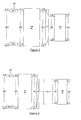
- La figure 1 illustre le concept de la technique de VBLAST appliquée sur un canal MIMO sélectif en fréquence ;
- La figure 2 illustre un procédé générique de codage de canal externe de l'information numérique, d'entrelacement, et de démultiplexage en K flux ;
- La figure 3 illustre un procédé de codage interne linéaire (ou d'étalement) spatio-temporel (ou spatio-fréquentiel) suivi d'un multiplexage sur T antennes d'émission ;
- La figure 4 illustre un procédé de codage interne linéaire (ou d'étalement) spatio-temporel (ou spatio-fréquentiel) suivi d'un multiplexage sur une voie unique, d'un entrelacement au niveau chip, puis d'un démultiplexage sur les T antennes d'émission ;
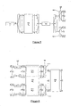
- La figure 5 illustre un procédé générique de codage de canal externe de l'information numérique, d'entrelacement, d'un premier démultiplexage en T flux (démultiplexage spatial) suivi d'un second démultiplexage en U flux (démultiplexage en codes) ;
- La figure 6 illustre un procédé de codage interne linéaire (ou d'étalement) temporel (ou fréquentiel) et de multiplexage indépendant par antenne, compatible avec le mode HSDPA de l'UMTS ;
- La figure 7 illustre un procédé de codage interne linéaire (ou d'étalement) temporel (ou fréquentiel) et de multiplexage indépendant par antenne suivi d'un multiplexage en flux unique, d'un entrelacement au niveau chip, puis d'un démultiplexage sur les T antennes d'émission, compatible avec le mode HSDPA de l'UMTS ;
- La figure 8 illustre le canal équivalent plat ergodique ou à évanouissement par blocs obtenue par la décomposition du MIMO sélectif en fréquence dans la base de Fourier et qui sert couramment de modèle pour les modulations multiporteuses.
- Figure 1 illustrates the concept of the VBLAST technique applied on a frequency-selective MIMO channel;
- FIG. 2 illustrates a generic method of external channel coding of digital information, of interleaving, and of demultiplexing in K streams;
- FIG. 3 illustrates a spatio-temporal (or space-frequency) linear (or spreading) internal coding process followed by multiplexing on transmit antennas;
- FIG. 4 illustrates a spatio-temporal linear (or spatio-frequency) internal coding (or spreading) method followed by single-channel multiplexing, chip-level interleaving and then demultiplexing on the T transmit antennas;
- FIG. 5 illustrates a generic method of external channel coding of the digital information, of interleaving, of a first T-stream demultiplexing (spatial demultiplexing) followed by a second U-shaped demultiplexing (code demultiplexing);
- FIG. 6 illustrates a method of linear (or spreading) temporal (or frequency) and independent antenna multiplexing, compatible with the HSDPA mode of the UMTS;
- FIG. 7 illustrates a method of linear (or time-domain) internal coding (or frequency) and independent multiplexing by antenna followed by single-stream multiplexing, chip-level interleaving and then demultiplexing on transmit antennas, compatible with HSDPA mode of UMTS;
- FIG. 8 illustrates the ergodic or block fading equivalent channel obtained by the decomposition of the frequency-selective MIMO in the Fourier base and which is commonly used as a model for multicarrier modulations.
La présente invention décrit un schéma de modulation/codage à grande efficacité spectrale, et haute capacité d'adaptabilité, reposant sur l'emploi de modulations par étalement de spectre et sur l'utilisation d'antennes multiples en émission et en réception. La solution proposée est pertinente sous l'hypothèse d'une absence de connaissance du canal à l'émission (pas de CSI) et d'une connaissance parfaite du canal en réception (CSI).The present invention describes a spectrally efficient, high adaptability modulation / coding scheme based on the use of spread spectrum modulations and the use of multiple transmit and receive antennas. The proposed solution is relevant under the assumption of a lack of knowledge of the channel on transmission (no CSI) and a perfect knowledge of the receiving channel (CSI).
Les données numériques utiles sont collectées et groupées en un message m de Ko bits constituant la source 101 des données numériques en émission. A tout message m, un code externe Co linéaire, de matrice génératrice G o de dimension No × Ko et construit sur F2 assigne en 102 un mot de code v de longueur No bits, défini par la relation matricielle :![]()
![]()
Le rendement de codage externe est :
La longueur N o des mots de code est liée aux différents paramètres du système par la relation :![]()
![]()
Après multiplexage 103, le mot de code v est envoyé dans un entrelaceur 104 (opérant au niveau binaire et, le cas échéant, doté d'une structure particulière). Dans une configuration de type accès multiple, l'entrelacement agit par morceaux sur les différents mots de code placés les uns à la suite des autres. La sortie de cet entrelaceur 104 est morcelée en KL q-uplets de bits, appelés entiers.After multiplexing 103, the codeword v is sent in an interleaver 104 (operating at the binary level and, where appropriate, having a particular structure). In a multiple access type configuration, the interleaving acts in pieces on the different code words placed one after the other. The output of this
Le flux d'entiers est soumis à un procédé de démultiplexage 105 sur K voies distinctes, K étant strictement supérieur à T, et choisi arbitrairement. La sortie de cette opération est une matrice d'entiers D de dimension K × L. Les L colonnes d[n] n = 0, ..., L -1 de cette matrice D possèdent la structure suivante :![]()
![]()
![]()
![]()
En référence à la figure 3, les entiers d k [n] de la matrice D sont ensuite individuellement modulés (107) en données modulées, et plus particulièrement ici en symboles complexes sk [n] d'une constellation ![]()
![]()
![]()
![]()
![]()
![]()
Il est utile de préciser les relations inverses suivantes :![]()
![]()
Plusieurs options sont possibles en ce qui concerne la définition de la matrice génératrice W, définissant un codage interne linéaire sur le corps des complexes (ou étalement), qui peuvent influer sur la structure de l'émetteur et sur les caractéristiques des front-ends linéaires en réception :
- Etalement (ou codage interne) périodique où W est réutilisée à chaque temps symbole. Pour garantir la décorrélation temporelle des échantillons de bruit affectant les chips lorsque l'on reforme le système à accès multiple après égalisation, un entrelacement chip doit être appliqué avant transmission sur le canal MIMO ; ou
- Etalement (ou codage interne) apériodique où W dépend explicitement du temps symbole. L'étalement apériodique garantit la décorrélation temporelle des échantillons de bruit affectant les chips lorsque l'on reforme le système à accès multiple après égalisation. L'entrelacement chip n'est plus nécessaire mais reste optionnel.
- Periodic spread (or internal coding) where W is reused at each symbol time. To guarantee the temporal decorrelation of the noise samples affecting the chips when the multiple access system is reformed after equalization, an interleaving chip must be applied before transmission on the MIMO channel; or
- Peripheral spread (or internal coding) where W explicitly depends on the symbol time. The aperiodic spread ensures the temporal decorrelation of the noise samples affecting the chips when the multiple access system is reformed after equalization. Interleaving chip is no longer necessary but remains optional.
Par ailleurs, l'étalement peut être spatio-temporel (ou spatio-fréquentiel) lorsqu'il est fait d'un bloc sur l'ensemble des antennes, ou uniquement temporel (ou fréquentiel) lorsqu'il est réalisé indépendamment par antenne.
Quatre principaux types de codages internes linéaires seront donc présentés ci-après :
- un codage interne linéaire (ou étalement) spatio-temporel (ou spatio-fréquentiel) apériodique ;
- un codage interne linéaire (ou étalement) temporel (ou fréquentiel) apériodique ;
- un codage interne linéaire (ou étalement) spatio-temporel (ou spatio-fréquentiel) périodique ;
- un codage interne linéaire (ou étalement) temporel (ou fréquentiel) périodique.
Four main types of linear internal coding will therefore be presented below:
- an aperiodic spatio-temporal linear (or spatio-frequential) internal coding (or spreading);
- an aperiodic (or periodic) linear (or frequency) internal coding (or spreading);
- periodic (or spatio-temporal) linear (or spanning) internal coding;
- periodic (or periodic) linear (or frequency) periodic internal coding.
En référence à la figure 3, on suppose ici un étalement spatio-temporel (spatio-fréquentiel) apériodique. L'étalement spatio-temporel (spatio-fréquentiel) est réalisé pour chaque matrice S au moyen d'une matrice de codage interne W n de dimension N × K avec :![]()
![]()
On appelle rapport de codage interne (ou load) du système le rapport :
La multiplication du vecteur de symboles s[n] par la matrice de codage interne W donne lieu à un vecteur :![]()
![]()
La relation peut également être écrite au niveau matriciel :![]()
![]()
![]()
![]()
![]()
![]()
![]()
![]()
Pour construire la matrice de codage interne W n , on dispose de N codes orthogonaux de longueur N. Le système est surchargé dès que :![]()
![]()
Considérons le résultat de la division polynomiale de K par N :![]()
![]()
Les K utilisateurs sont donc répartis en A groupes saturés de N utilisateurs, et 1 groupe non saturé de B utilisateurs. On pose :
![]()

![]()
![]()
![]()
On appelle matrice d'embrouillage pour le groupe saturé d'utilisateurs i = 1,..., A et on note :

Cette matrice d'embrouillage va ainsi permettre de garantir une décorrélation des flux de chips émis sur les différentes antennes (au moyen des codes d'embrouillage), lorsqu'on l'applique à la matrice d'étalement pour former la matrice de codage interne W n comme suit :
This scrambling matrix will thus make it possible to guarantee a decorrelation of the streams of chips emitted on the various antennas (by means of the scrambling codes), when it is applied to the spreading matrix to form the internal coding matrix. W n as follows:
Elle peut toujours être écrite sous la forme : 
Dans cette autre variante selon l'invention, en référence à la figure 6, compatible avec le mode HSDPA de la norme UMTS, on dispose de SF codes orthogonaux de longueur SF .
Le paramètre N est toujours un multiple de T :![]()
The parameter N is always a multiple of T: ![]()
Les SF codes à disposition sont réutilisés sur chaque antenne d'émission (principe dit du « code re-use »). L'étalement, réalisé indépendamment par antenne, est temporel ou fréquentiel. Ceci impose que K soit également un multiple de T :![]()
![]()
Cette condition non limitative selon l'invention entraîne alors une nouvelle expression du rendement de codage interne (encore appelé load) :
La matrice de codage interne W n possède une structure diagonale par blocs :
![]()
![]()
En référence à la figure 6, le vecteur d'entier d [n] (démultiplexé en 105, après avoir été codé en 102 et entrelacé en 104) émis à l'instant n possède la structure particulière suivante :![]()
![]()
![]()
![]()
En référence à la figure 6, la modulation 107 de ces données multiplexées d [n] donne un vecteur de symboles émis à l'instant n ayant la structure particulière suivante :![]()
![]()
![]()
![]()
La multiplication 108 du vecteur de symboles s [n] par la matrice de codage interne W n donne lieu au vecteur :![]()
![]()
![]()
![]()
![]()
![]()
Pour chaque antenne t, le vecteur de chips z (t)[n] est ensuite multiplexé en 109-t sur l'antenne d'émission t qui lui est associée.
On remarquera que, dans cette variante d'émission, la récupération de la diversité spatiale s'effectue au travers du code G0 (en 102) et de l'entrelacement binaire (en 104) externes. La capacité de surcharge, connue pour augmenter avec la longueur des codes d'étalement, est moindre.For each antenna t, the chip vector z ( t ) [ n ] is then multiplexed at 109-t on the transmitting antenna t associated therewith.
It will be noted that, in this transmission variant, the recovery of the spatial diversity is carried out through external code G 0 (at 102) and binary interleaving (at 104). The overload capacity, known to increase with the length of the spreading codes, is less.
Les conditions de surcharge et la construction explicite de la matrice W n peuvent être précisées. Le système est surchargé dès que :![]()
![]()
Ceci n'implique pas nécessairement U > SF (c'est-à-dire qu'il n'y a pas nécessairement une surcharge par antenne).
Lorsque U > SF, les différentes antennes sont individuellement surchargées. L'inégalité T × U > SF est alors trivialement vérifiée et le système à antennes multiples est qualifié d'entièrement surchargé.
On considère le résultat de la division polynomiale de U par SF :![]()
When U> S F , the different antennas are individually overloaded. The inequality T × U> S F is then trivially verified and the multiple antenna system is qualified as fully overloaded.
We consider the result of the polynomial division of U by S F : ![]()
Les U utilisateurs associés à chacune des antennes d'émission sont donc répartis en A groupes saturés de SF utilisateurs, et 1 groupe non saturé de B utilisateurs.
On :pose :
![]()

![]()
On: poses: ![]()
![]()
On appelle matrice d'embrouillage pour le groupe saturé d'utilisateurs i = 1,..., A et on note :

Cette matrice d'embrouillage associée au bloc W n (t) (de l'antenne t = 1,...,T) va ainsi permettre de garantir une décorrélation des flux de chips émis sur l'antenne t (au moyen des codes d'embrouillage), lorsqu'on l'applique à la matrice d'étalement pour former le bloc W n (t) de la matrice de codage interne W n comme suit : 

This scrambling matrix associated with the block W n ( t ) (of the antenna t = 1, ..., T ) will thus make it possible to guarantee a decorrelation of the streams of chips transmitted on the antenna t (by means of the codes scrambling), when applied to the spreading matrix to form the block W n ( t ) of the internal coding matrix W n as follows:
Remarque : Pour des raisons de simplicité évidentes, a été traité dans ce chapitre un cas où la matrice W n de codage interne est constituée de blocs ![]()
Ce cas peut être étendu à des cas plus généraux où la matrice W n de codage interne est constituée de blocs de dimensions différentes les uns par rapport aux autres, et notamment le cas plus général où le bloc ![]()
![]()
This case can be extended to more general cases where the matrix W n of internal coding consists of blocks of different dimensions with respect to each other, and in particular the more general case where the block ![]()
La matrice W n est donc de dimension NxK avec 
On pourra alors adapter le procédé d'émission à cette variante.We can then adapt the emission process to this variant.
Le traitement est ici identique à celui réalisé au chapitre 1.5 ou 1.6, à l'exception que la matrice génératrice est ici appliquée de façon périodique dans le temps, et s'exprime :![]()
![]()
En référence aux figures 4 et 7, on suppose ici un codage linéaire interne (ou étalement) quelconque correspondant à l'une des stratégies décrites dans les chapitres 1.5 à 1.7 , mais qui est ici couplé à un entrelacement chip 108.
Apres étalement par chip 108, les vecteurs de chips z[n] n = 0,..., L -1 sont multiplexés en 109 en un flux de chips unique. Le flux de chips attaque alors un entrelaceur 110, dont la sortie est démultiplexée en 111 en T flux de chips distincts), un par antenne d'émission. Cette opération a pour effet de transformer la matrice de chips Z de dimension N × L :![]()
![]()
![]()
After spreading by ![]()
![]()
![]()
Le procédé d'émission s'inscrit naturellement dans la classe générale des codes espace-temps. L'efficacité spectrale du système (en bits par utilisation du canal), sous l'hypothèse d'un filtre de Nyquist idéal à bande limitée, est égale à :![]()
![]()
En pratique, le filtre de mise en forme à l'émission présente un facteur ε de débordement non nul (roll-off). En réception, on applique un filtre adapté à ce filtre d'émission pour toutes les antennes de réception. Il est supposé que les fonctions d'estimation de canal et de synchronisation de rythme et de porteuse sont réalisées de telle sorte que les coefficients de la réponse impulsionnelle du canal soient espacés régulièrement d'une valeur égale au temps chip (canal équivalent en bande de base discret au temps chip). Cette hypothèse est légitime, le théorème d'échantillonnage de Shannon imposant un échantillonnage au rythme (1 + ε) / Tc qui peut être approché par 1/Tc lorsque ε est petit.
On pourra généraliser de façon directe des expressions qui suivent à un échantillonnage égal à un multiple de 1/Tc .In practice, the transmission shaping filter has a non-zero overflow factor ε (roll-off). In reception, a filter adapted to this transmission filter is applied for all the receiving antennas. It is assumed that the channel estimation and timing and carrier synchronization functions are performed such that the channel impulse response coefficients are regularly spaced by a value equal to chip time (discrete baseband equivalent channel at chip time). This hypothesis is legitimate, Shannon's sampling theorem imposing a sampling at the rate (1 + ε ) / T c which can be approximated by 1 / T c when ε is small.
We can generalize directly expressions that follow to a sampling equal to a multiple of 1 / T c .
La transmission s'effectue sur un canal B-blocs à entrées et sorties multiples (MIMO) sélectif en fréquence :![]()
![]()
Le canal H (b) est supposé constant sur Lx chips avec la convention :![]()
![]()
La matrice de chips X peut être segmentée en B matrices de chips distinctes X (1),...,X (B), de dimension T × LX (complétées à droite et à gauche par des zéros physiques ou temps de garde si besoin est), chaque matrice X (b) voyant le canal H (b).
Les cas extrêmes du modèle B-blocs sont les suivants :
- B = 1 et Lx = LSF modèle quasi-statique
- B = LSF et LX = 1 modèle ergodique (chip)
The extreme cases of the B-block model are as follows:
- B = 1 and L x = LS F quasi-static model
- B = LS F and L X = 1 ergodic model (chip)
Une renumérotation des chips est appliquée à l'intérieur de chaque bloc.A renumbering of the chips is applied inside each block.
Pour tout indice de bloc b, le modèle de canal équivalent en bande de base à temps discret (rythme chip) permet d'écrire le vecteur reçu![]()

![]()
![]()
![]()

![]()
![]()
![]()
![]()
On suppose ici que le débit est très élevé et que la fréquence Doppler du canal est faible, de telle sorte que Lx >> SF. Pour le mode HSDPA de la norme UMTS, le canal est quasi-statique, c'est à dire lorsque B=1 .It is assumed here that the rate is very high and the Doppler frequency of the channel is low, so that L x >> S F. For HSDPA mode of the UMTS standard, the channel is quasi-static, ie when B = 1.
Le codage interne linéaire 108 est ici spatio-fréquentiel ou fréquentiel. En référence à la figure 8, il est bien connu de l'homme de l'art que l'introduction en 120 d'une IFFT en émission et en 220 d'une FFT en réception (aux entrelacements près) rend un canal équivalent non sélectif en fréquence (canal modélisé par une matrice circulante grâce à l'emploi de préfixes cycliques, puis rendu diagonal dans la base de Fourier). Ainsi chaque porteuse voit un canal équivalent MIMO plat. Sous le formalisme précédemment présenté, le canal après FFT peut être vu comme un canal non sélectif (P = 1, M = 0) et B-blocs.The linear
L'émission selon l'invention concerne non seulement un procédé permettant sa mise en oeuvre, mais aussi le système apte à l'exécuter.The emission according to the invention relates not only to a method for its implementation, but also to the system capable of executing it.
Claims (25)
- Sending method for multiple users desiring to transmit digital data on a frequency-selective channel with several send antennas and several receive antennas, characterized in that it implements on coded and interleaved data (d[n]):- a K-pathway demultiplexing (105), where K is strictly greater than the number T of send antennas, and a modulation (107) of the data thus demultiplexed;- a linear inner coding (108) defined by a generating matrix (W, W n) of dimensions NxK where N is strictly greater than T, this inner coding being applied to the vectors of dimension K of the modulated data.
- Method according to Claim 1, characterized in that the efficiency K/N of the linear inner coding is strictly greater than 1.
- Method according to one of the preceding claims, characterized in that the said generating matrix (W,Wn) is constructed on the basis of N orthogonal spreading codes of length N, ensuring a spreading factor equal to N.
- Method according to Claim 3, characterized in that the spreading codes are reused several times in the generating matrix (W,W n) to form therein several groups of spreading codes, so that the spreading codes of each group of spreading codes are mutually orthogonal.
- Method according to Claim 4, characterized in that the said generating matrix (W n, W) is furthermore constructed on the basis of several scrambling codes (Σ) overlayed on the spreading codes, so that to each group of spreading codes is allocated an inherent scrambling code.
- Method according to Claim 1 or 2, characterized in that the inner linear coding is implemented independently on each of the T send antennas and applies for the antenna referenced t on a modulated data vector of dimension Ut strictly greater than 1, with

- Method according to the preceding claim, characterized in that the dimension Ut of the block associated with antenna t is the same as that of each of the other blocks of the generating matrix (W, W n), Ut then being denoted U and each block being of dimension (N/T)xU.
- Method according to Claim 6 or 7, characterized in that each of the said blocks of the generating matrix is constructed on the basis of N/T orthogonal spreading codes of length N/T, ensuring a spreading factor N/T.
- Method according to one of Claims 6 to 8, characterized in that the blocks are constructed on the basis of the same orthogonal spreading codes.
- Method according to one of Claims 6 to 9, characterized in that the generating matrix is furthermore constructed on the basis of several scrambling codes (Σ) overlayed on the spreading codes, so that each of the said blocks of the spreading matrix is allocated an inherent scrambling code.
- Method according to one of Claims 6 to 10, characterized in that K is strictly greater than N/T.
- Method according to one of Claims 6 to 9, characterized in that Ut is strictly greater than N/T for any t.
- Method according to Claim 12, characterized in that each of the said blocks is constructed on the basis of several groups of spreading codes, each group being constructed on the basis of N/T orthogonal codes of length N/T, ensuring a spreading factor N/T, the N/T spreading codes being reused several times per block to form the said several groups of block spreading codes, so that the spreading codes of each group of spreading codes are mutually orthogonal.
- Method according to Claim 13, characterized in that the generating matrix (W,W n) is furthermore constructed on the basis of scrambling codes (Σ) overlayed on the spreading codes, so that to each group of spreading codes is allocated an inherent scrambling code, the said scrambling codes being distinct from one another group-wise and block-wise.
- Sending method according to one of the preceding claims, characterized in that it furthermore comprises, after the linear inner coding (108):(a) a multiplexing (109);(b) an interleaving (110) of the data thus multiplexed;(c) a demultiplexing (111) to distribute the data thus interleaved over the T send antennas.
- Sending method according to one of Claims 1 to 14, characterized in that it furthermore comprises, after the linear inner coding (108), a multiplexing (111) to distribute the data over the T send antennas.
- Sending method according to one of the preceding claims, characterized in that the linear inner coding (108) is applied to the data modulated in a periodic manner over time.
- Method according to one of Claims 1 to 16, characterized in that the linear inner coding (108) is applied to the data modulated in an aperiodic manner over time.
- Method according to one of the preceding claims, characterized in that it furthermore comprises, before the said demultiplexing (105), at least one outer coding (102) of the digital data originating from one or more users and an interleaving (104) to form the said coded and interleaved data (d[n]).
- Sending method according to one of the preceding claims, characterized in that the linear inner coding is carried out frequency-wise, and in that the transmission is of multicarrier type.
- Sending method according to one of Claims 1 to 19, characterized in that the linear inner coding is carried out time-wise, and in that the transmission is of monocarrier type.
- Sending system for multiple users desiring to transmit digital data on a frequency-selective channel with several send antennas and several receive antennas, characterized in that it comprises:- a demultiplexer (105) of coded and interleaved data (d[n]) on K pathways, where K is strictly greater than the number T of send antennas;- a modulator (107) of the output data of the demultiplexer;- a linear inner encoder (108) able to code by means of a generating matrix (W,W n) of dimensions NxK where N is strictly greater than T, this inner coding being applied to vectors of dimension K of the data output by the modulator;- T send antennas.
- System according to Claim 22, characterized in that it furthermore comprises:- a multiplexer (109) of the data coded by the said inner encoder (108);- an interleaver (110) of the data thus multiplexed;- a demultiplexer (111) for distributing the data thus interleaved over the T send antennas.
- System according to Claim 22, characterized in that it furthermore comprises a multiplexer (111) of the data coded by the said inner encoder (108) for distributing the data thus interleaved over the T send antennas.
- System according to one of Claims 22 to 24, characterized in that it furthermore comprises, upstream of the demultiplexer (105):- at least one encoder (102) of the digital data originating from one or more users;- an interleaver at the binary level (104).
Priority Applications (9)
| Application Number | Priority Date | Filing Date | Title |
|---|---|---|---|
| AT04291041T ATE372002T1 (en) | 2004-04-22 | 2004-04-22 | TRANSMISSION TO CDMA COMMUNICATION SYSTEM THROUGH A MIMO CHANNEL |
| ES04291041T ES2293180T3 (en) | 2004-04-22 | 2004-04-22 | ISSUANCE FOR CDMA COMMUNICATIONS SYSTEMS ON MIMO CHANNEL. |
| EP04291041A EP1589686B1 (en) | 2004-04-22 | 2004-04-22 | Transmission for CDMA communications system on MIMO channel |
| DE602004008579T DE602004008579T2 (en) | 2004-04-22 | 2004-04-22 | Transmission to the CDMA communication system through a MIMO channel |
| KR1020067024372A KR101107631B1 (en) | 2004-04-22 | 2005-04-21 | Emission for cdma communications systems on the mimo channel |
| JP2007508866A JP4809328B2 (en) | 2004-04-22 | 2005-04-21 | Radiation for CDMA communication systems over MIMO channels |
| CN200580020550.9A CN1973474B (en) | 2004-04-22 | 2005-04-21 | On frequency-selective channel, the method and system of data is transmitted by multiple user |
| US11/587,222 US7885316B2 (en) | 2004-04-22 | 2005-04-21 | Emission for CDMA communications systems on the MIMO channel |
| PCT/EP2005/004411 WO2005114888A1 (en) | 2004-04-22 | 2005-04-21 | Emission for cdma communications szstems on the mimo channel |
Applications Claiming Priority (1)
| Application Number | Priority Date | Filing Date | Title |
|---|---|---|---|
| EP04291041A EP1589686B1 (en) | 2004-04-22 | 2004-04-22 | Transmission for CDMA communications system on MIMO channel |
Publications (2)
| Publication Number | Publication Date |
|---|---|
| EP1589686A1 EP1589686A1 (en) | 2005-10-26 |
| EP1589686B1 true EP1589686B1 (en) | 2007-08-29 |
Family
ID=34931047
Family Applications (1)
| Application Number | Title | Priority Date | Filing Date |
|---|---|---|---|
| EP04291041A Expired - Lifetime EP1589686B1 (en) | 2004-04-22 | 2004-04-22 | Transmission for CDMA communications system on MIMO channel |
Country Status (9)
| Country | Link |
|---|---|
| US (1) | US7885316B2 (en) |
| EP (1) | EP1589686B1 (en) |
| JP (1) | JP4809328B2 (en) |
| KR (1) | KR101107631B1 (en) |
| CN (1) | CN1973474B (en) |
| AT (1) | ATE372002T1 (en) |
| DE (1) | DE602004008579T2 (en) |
| ES (1) | ES2293180T3 (en) |
| WO (1) | WO2005114888A1 (en) |
Families Citing this family (11)
| Publication number | Priority date | Publication date | Assignee | Title |
|---|---|---|---|---|
| JP5084051B2 (en) * | 2006-09-06 | 2012-11-28 | シャープ株式会社 | Transmission / reception device, transmission / reception system, and transmission / reception method |
| WO2008120925A1 (en) | 2007-03-29 | 2008-10-09 | Lg Electronics Inc. | Method of transmitting sounding reference signal in wireless communication system |
| US8599819B2 (en) | 2007-06-19 | 2013-12-03 | Lg Electronics Inc. | Method of transmitting sounding reference signal |
| KR101397039B1 (en) | 2007-08-14 | 2014-05-20 | 엘지전자 주식회사 | Signal Transmission Method Using CDM Against The Effect Of Channel Estimation Error in Transmit Diversity System |
| RU2439809C2 (en) | 2007-08-14 | 2012-01-10 | Эл Джи Электроникс Инк. | Method of acquiring resource region information for phich and method of receiving pdcch |
| WO2009022790A1 (en) | 2007-08-14 | 2009-02-19 | Lg Electronics Inc. | Method of transmitting data in a wireless communication system |
| KR101405974B1 (en) | 2007-08-16 | 2014-06-27 | 엘지전자 주식회사 | Methods for transmitting codewords in multiple input multiple output system |
| KR101507785B1 (en) | 2007-08-16 | 2015-04-03 | 엘지전자 주식회사 | A method for transmitting channel quality information in a MIMO (Multiple Input Multiple Output) system |
| US8995559B2 (en) | 2008-03-28 | 2015-03-31 | Qualcomm Incorporated | Signaling message transmission in a wireless communication network |
| WO2011124024A1 (en) * | 2010-04-07 | 2011-10-13 | 上海贝尔股份有限公司 | Method and apparatus for feeding back and constructing correlation matrix in multi-input multi-output system |
| DE102011079972B4 (en) * | 2011-07-28 | 2017-07-06 | Siemens Convergence Creators Gmbh | Method for transmitting information data |
Family Cites Families (15)
| Publication number | Priority date | Publication date | Assignee | Title |
|---|---|---|---|---|
| CA2302289C (en) * | 1996-08-29 | 2005-11-08 | Gregory G. Raleigh | Spatio-temporal processing for communication |
| EP1035677A1 (en) | 1999-03-10 | 2000-09-13 | Lucent Technologies Inc. | Code branch allocation for CDMA systems |
| US6351499B1 (en) * | 1999-12-15 | 2002-02-26 | Iospan Wireless, Inc. | Method and wireless systems using multiple antennas and adaptive control for maximizing a communication parameter |
| US20020154705A1 (en) * | 2000-03-22 | 2002-10-24 | Walton Jay R. | High efficiency high performance communications system employing multi-carrier modulation |
| US7068628B2 (en) * | 2000-05-22 | 2006-06-27 | At&T Corp. | MIMO OFDM system |
| US6879576B1 (en) | 2000-09-06 | 2005-04-12 | Qualcomm Incorporated | Method and apparatus for processing a physical channel with partial transport format information |
| DE60037759T2 (en) * | 2000-10-27 | 2009-01-15 | Nortel Networks Ltd., St. Laurent | Method for space-time coding and corresponding transmitter |
| FR2821217B1 (en) * | 2001-02-21 | 2003-04-25 | France Telecom | METHOD AND SYSTEM FOR ITERATIVE CODING-DECODING OF DIGITAL DATA STREAMS ENCODED BY SPATIO-TEMPORAL COMBINATIONS, IN MULTIPLE TRANSMISSION AND RECEPTION |
| US7133459B2 (en) * | 2001-05-01 | 2006-11-07 | Texas Instruments Incorporated | Space-time transmit diversity |
| CN100438389C (en) * | 2001-06-21 | 2008-11-26 | 皇家菲利浦电子有限公司 | MIMO Transmission System in Radio Communication Network |
| JP3996126B2 (en) * | 2001-11-29 | 2007-10-24 | インターデイジタル テクノロジー コーポレーション | An efficient multiple-input/multiple-output system for multipath fading channels. |
| US7542446B2 (en) * | 2002-07-31 | 2009-06-02 | Mitsubishi Electric Research Laboratories, Inc. | Space time transmit diversity with subgroup rate control and subgroup antenna selection in multi-input multi-output communications systems |
| KR100457188B1 (en) | 2002-10-07 | 2004-11-16 | 한국전자통신연구원 | Method and apparatus for mc/mc-ds dual-mode spreading for adaptive multicarrier code division multiple access system |
| DE60320250T2 (en) * | 2003-08-29 | 2008-07-10 | Mitsubishi Denki K.K. | Method for transmitting data in a telecommunication system |
| TWI264194B (en) * | 2004-02-06 | 2006-10-11 | Univ Nat Chiao Tung | Framework and method for multiple-input multiple-output (MIMO) multi-carrier code division multiple access communication system |
-
2004
- 2004-04-22 AT AT04291041T patent/ATE372002T1/en not_active IP Right Cessation
- 2004-04-22 DE DE602004008579T patent/DE602004008579T2/en not_active Expired - Lifetime
- 2004-04-22 ES ES04291041T patent/ES2293180T3/en not_active Expired - Lifetime
- 2004-04-22 EP EP04291041A patent/EP1589686B1/en not_active Expired - Lifetime
-
2005
- 2005-04-21 CN CN200580020550.9A patent/CN1973474B/en not_active Expired - Lifetime
- 2005-04-21 KR KR1020067024372A patent/KR101107631B1/en not_active Expired - Lifetime
- 2005-04-21 WO PCT/EP2005/004411 patent/WO2005114888A1/en not_active Ceased
- 2005-04-21 US US11/587,222 patent/US7885316B2/en active Active
- 2005-04-21 JP JP2007508866A patent/JP4809328B2/en not_active Expired - Lifetime
Non-Patent Citations (1)
| Title |
|---|
| None * |
Also Published As
| Publication number | Publication date |
|---|---|
| US7885316B2 (en) | 2011-02-08 |
| CN1973474A (en) | 2007-05-30 |
| US20070206662A1 (en) | 2007-09-06 |
| KR101107631B1 (en) | 2012-01-25 |
| DE602004008579T2 (en) | 2008-05-15 |
| WO2005114888A8 (en) | 2007-06-21 |
| KR20070038958A (en) | 2007-04-11 |
| WO2005114888A1 (en) | 2005-12-01 |
| DE602004008579D1 (en) | 2007-10-11 |
| ES2293180T3 (en) | 2008-03-16 |
| CN1973474B (en) | 2015-10-07 |
| JP4809328B2 (en) | 2011-11-09 |
| EP1589686A1 (en) | 2005-10-26 |
| ATE372002T1 (en) | 2007-09-15 |
| JP2007534246A (en) | 2007-11-22 |
Similar Documents
| Publication | Publication Date | Title |
|---|---|---|
| EP2087675B1 (en) | Transmission/reception methods and modules for a multiple-carrier multiple-antenna system with training sequence | |
| EP1690361B1 (en) | Method for the multi-antenna transmission of a linearly-precoded signal, corresponding devices, signal and reception method | |
| EP1981203B1 (en) | Method and multiple-antenna device for signal transmission | |
| EP2161863A1 (en) | Transmitting method, transmitting device, receiving method, and receiving device | |
| EP2156590B1 (en) | Transmission and reception of multicarrier spread-spectrum signals | |
| EP1589686B1 (en) | Transmission for CDMA communications system on MIMO channel | |
| EP2255475B1 (en) | Method for transmitting multi-carrier signals in a multi-antenna system | |
| EP1898581A1 (en) | Method and module for estimation of transmission channels of a multi antenna multi carrier system | |
| EP1738513B1 (en) | Method for sending a signal in a multi-antenna system, corresponding signal and method for channel estimation | |
| EP1969792A2 (en) | Dynamic interleaving method and device | |
| EP2850797B1 (en) | Method for high bit rate wireless communication using a multiple output receiver | |
| EP1589672B1 (en) | Iterative vectorized equalization method for CDMA communications systems on MIMO channel | |
| EP1589673B1 (en) | Iterative multiuser detection method for CDMA communications systems on MIMO canal | |
| EP2731306A2 (en) | Method and system for channel de-synchronization in multicarrier communication systems | |
| WO2007090995A2 (en) | Method for receiving a signal using an improved propagation channel estimate, corresponding receiver device and computer programme product | |
| Labade et al. | Spectral efficiency enhancement through Wavelet Transform (WT) for 5G | |
| KR101019172B1 (en) | Apparatus and method for transmitting / receiving data in a communication system using U-BSLAT OPM system | |
| Reda et al. | Performance Analysis of Combining Beamforming and ZF/MMSE-SIC Equalization Techniques for MIMO DWPT-COFDM Systems | |
| Louveaux | Rostom Zakaria Conception d’émetteur et récepteur pour l’élimination des interférences intrinsèques dans les systèmes multiporteuses à base de bancs de filtres et à antennes multiples. | |
| EP1624591A1 (en) | Method for spatial diversity radio transmission and transmitter therefor |
Legal Events
| Date | Code | Title | Description |
|---|---|---|---|
| PUAI | Public reference made under article 153(3) epc to a published international application that has entered the european phase |
Free format text: ORIGINAL CODE: 0009012 |
|
| AK | Designated contracting states |
Kind code of ref document: A1 Designated state(s): AT BE BG CH CY CZ DE DK EE ES FI FR GB GR HU IE IT LI LU MC NL PL PT RO SE SI SK TR |
|
| AX | Request for extension of the european patent |
Extension state: AL HR LT LV MK |
|
| AKX | Designation fees paid | ||
| 17P | Request for examination filed |
Effective date: 20060627 |
|
| RBV | Designated contracting states (corrected) |
Designated state(s): AT BE BG CH CY CZ DE DK EE ES FI FR GB GR HU IE IT LI LU MC NL PL PT RO SE SI SK TR |
|
| REG | Reference to a national code |
Ref country code: DE Ref legal event code: 8566 |
|
| GRAP | Despatch of communication of intention to grant a patent |
Free format text: ORIGINAL CODE: EPIDOSNIGR1 |
|
| GRAS | Grant fee paid |
Free format text: ORIGINAL CODE: EPIDOSNIGR3 |
|
| GRAA | (expected) grant |
Free format text: ORIGINAL CODE: 0009210 |
|
| AK | Designated contracting states |
Kind code of ref document: B1 Designated state(s): AT BE BG CH CY CZ DE DK EE ES FI FR GB GR HU IE IT LI LU MC NL PL PT RO SE SI SK TR |
|
| REG | Reference to a national code |
Ref country code: GB Ref legal event code: FG4D Free format text: NOT ENGLISH |
|
| REG | Reference to a national code |
Ref country code: CH Ref legal event code: EP |
|
| REG | Reference to a national code |
Ref country code: IE Ref legal event code: FG4D Free format text: LANGUAGE OF EP DOCUMENT: FRENCH |
|
| REF | Corresponds to: |
Ref document number: 602004008579 Country of ref document: DE Date of ref document: 20071011 Kind code of ref document: P |
|
| GBT | Gb: translation of ep patent filed (gb section 77(6)(a)/1977) |
Effective date: 20071212 |
|
| PG25 | Lapsed in a contracting state [announced via postgrant information from national office to epo] |
Ref country code: FI Free format text: LAPSE BECAUSE OF FAILURE TO SUBMIT A TRANSLATION OF THE DESCRIPTION OR TO PAY THE FEE WITHIN THE PRESCRIBED TIME-LIMIT Effective date: 20070829 Ref country code: NL Free format text: LAPSE BECAUSE OF FAILURE TO SUBMIT A TRANSLATION OF THE DESCRIPTION OR TO PAY THE FEE WITHIN THE PRESCRIBED TIME-LIMIT Effective date: 20070829 |
|
| NLV1 | Nl: lapsed or annulled due to failure to fulfill the requirements of art. 29p and 29m of the patents act | ||
| PG25 | Lapsed in a contracting state [announced via postgrant information from national office to epo] |
Ref country code: AT Free format text: LAPSE BECAUSE OF FAILURE TO SUBMIT A TRANSLATION OF THE DESCRIPTION OR TO PAY THE FEE WITHIN THE PRESCRIBED TIME-LIMIT Effective date: 20070829 Ref country code: PL Free format text: LAPSE BECAUSE OF FAILURE TO SUBMIT A TRANSLATION OF THE DESCRIPTION OR TO PAY THE FEE WITHIN THE PRESCRIBED TIME-LIMIT Effective date: 20070829 |
|
| REG | Reference to a national code |
Ref country code: ES Ref legal event code: FG2A Ref document number: 2293180 Country of ref document: ES Kind code of ref document: T3 |
|
| REG | Reference to a national code |
Ref country code: IE Ref legal event code: FD4D |
|
| PG25 | Lapsed in a contracting state [announced via postgrant information from national office to epo] |
Ref country code: GR Free format text: LAPSE BECAUSE OF FAILURE TO SUBMIT A TRANSLATION OF THE DESCRIPTION OR TO PAY THE FEE WITHIN THE PRESCRIBED TIME-LIMIT Effective date: 20071130 |
|
| PG25 | Lapsed in a contracting state [announced via postgrant information from national office to epo] |
Ref country code: PT Free format text: LAPSE BECAUSE OF FAILURE TO SUBMIT A TRANSLATION OF THE DESCRIPTION OR TO PAY THE FEE WITHIN THE PRESCRIBED TIME-LIMIT Effective date: 20080129 Ref country code: IE Free format text: LAPSE BECAUSE OF FAILURE TO SUBMIT A TRANSLATION OF THE DESCRIPTION OR TO PAY THE FEE WITHIN THE PRESCRIBED TIME-LIMIT Effective date: 20070829 Ref country code: CZ Free format text: LAPSE BECAUSE OF FAILURE TO SUBMIT A TRANSLATION OF THE DESCRIPTION OR TO PAY THE FEE WITHIN THE PRESCRIBED TIME-LIMIT Effective date: 20070829 Ref country code: SK Free format text: LAPSE BECAUSE OF FAILURE TO SUBMIT A TRANSLATION OF THE DESCRIPTION OR TO PAY THE FEE WITHIN THE PRESCRIBED TIME-LIMIT Effective date: 20070829 |
|
| PG25 | Lapsed in a contracting state [announced via postgrant information from national office to epo] |
Ref country code: SE Free format text: LAPSE BECAUSE OF FAILURE TO SUBMIT A TRANSLATION OF THE DESCRIPTION OR TO PAY THE FEE WITHIN THE PRESCRIBED TIME-LIMIT Effective date: 20071129 Ref country code: RO Free format text: LAPSE BECAUSE OF FAILURE TO SUBMIT A TRANSLATION OF THE DESCRIPTION OR TO PAY THE FEE WITHIN THE PRESCRIBED TIME-LIMIT Effective date: 20070829 |
|
| PLBE | No opposition filed within time limit |
Free format text: ORIGINAL CODE: 0009261 |
|
| STAA | Information on the status of an ep patent application or granted ep patent |
Free format text: STATUS: NO OPPOSITION FILED WITHIN TIME LIMIT |
|
| 26N | No opposition filed |
Effective date: 20080530 |
|
| BERE | Be: lapsed |
Owner name: FRANCE TELECOM Effective date: 20080430 |
|
| PG25 | Lapsed in a contracting state [announced via postgrant information from national office to epo] |
Ref country code: MC Free format text: LAPSE BECAUSE OF NON-PAYMENT OF DUE FEES Effective date: 20080430 |
|
| REG | Reference to a national code |
Ref country code: CH Ref legal event code: PL |
|
| PG25 | Lapsed in a contracting state [announced via postgrant information from national office to epo] |
Ref country code: EE Free format text: LAPSE BECAUSE OF FAILURE TO SUBMIT A TRANSLATION OF THE DESCRIPTION OR TO PAY THE FEE WITHIN THE PRESCRIBED TIME-LIMIT Effective date: 20070829 Ref country code: LI Free format text: LAPSE BECAUSE OF NON-PAYMENT OF DUE FEES Effective date: 20080430 Ref country code: CH Free format text: LAPSE BECAUSE OF NON-PAYMENT OF DUE FEES Effective date: 20080430 |
|
| PG25 | Lapsed in a contracting state [announced via postgrant information from national office to epo] |
Ref country code: BE Free format text: LAPSE BECAUSE OF NON-PAYMENT OF DUE FEES Effective date: 20080430 |
|
| PG25 | Lapsed in a contracting state [announced via postgrant information from national office to epo] |
Ref country code: SI Free format text: LAPSE BECAUSE OF FAILURE TO SUBMIT A TRANSLATION OF THE DESCRIPTION OR TO PAY THE FEE WITHIN THE PRESCRIBED TIME-LIMIT Effective date: 20070829 |
|
| PG25 | Lapsed in a contracting state [announced via postgrant information from national office to epo] |
Ref country code: CY Free format text: LAPSE BECAUSE OF FAILURE TO SUBMIT A TRANSLATION OF THE DESCRIPTION OR TO PAY THE FEE WITHIN THE PRESCRIBED TIME-LIMIT Effective date: 20070829 |
|
| PG25 | Lapsed in a contracting state [announced via postgrant information from national office to epo] |
Ref country code: BG Free format text: LAPSE BECAUSE OF FAILURE TO SUBMIT A TRANSLATION OF THE DESCRIPTION OR TO PAY THE FEE WITHIN THE PRESCRIBED TIME-LIMIT Effective date: 20071129 |
|
| PG25 | Lapsed in a contracting state [announced via postgrant information from national office to epo] |
Ref country code: DK Free format text: LAPSE BECAUSE OF FAILURE TO SUBMIT A TRANSLATION OF THE DESCRIPTION OR TO PAY THE FEE WITHIN THE PRESCRIBED TIME-LIMIT Effective date: 20070829 |
|
| PG25 | Lapsed in a contracting state [announced via postgrant information from national office to epo] |
Ref country code: LU Free format text: LAPSE BECAUSE OF NON-PAYMENT OF DUE FEES Effective date: 20080422 Ref country code: HU Free format text: LAPSE BECAUSE OF FAILURE TO SUBMIT A TRANSLATION OF THE DESCRIPTION OR TO PAY THE FEE WITHIN THE PRESCRIBED TIME-LIMIT Effective date: 20080301 |
|
| PG25 | Lapsed in a contracting state [announced via postgrant information from national office to epo] |
Ref country code: TR Free format text: LAPSE BECAUSE OF FAILURE TO SUBMIT A TRANSLATION OF THE DESCRIPTION OR TO PAY THE FEE WITHIN THE PRESCRIBED TIME-LIMIT Effective date: 20070829 |
|
| REG | Reference to a national code |
Ref country code: FR Ref legal event code: PLFP Year of fee payment: 13 |
|
| REG | Reference to a national code |
Ref country code: FR Ref legal event code: PLFP Year of fee payment: 14 |
|
| REG | Reference to a national code |
Ref country code: FR Ref legal event code: PLFP Year of fee payment: 15 |
|
| PGFP | Annual fee paid to national office [announced via postgrant information from national office to epo] |
Ref country code: FR Payment date: 20230321 Year of fee payment: 20 |
|
| PGFP | Annual fee paid to national office [announced via postgrant information from national office to epo] |
Ref country code: IT Payment date: 20230322 Year of fee payment: 20 Ref country code: GB Payment date: 20230322 Year of fee payment: 20 |
|
| PGFP | Annual fee paid to national office [announced via postgrant information from national office to epo] |
Ref country code: ES Payment date: 20230502 Year of fee payment: 20 Ref country code: DE Payment date: 20230321 Year of fee payment: 20 |
|
| REG | Reference to a national code |
Ref country code: DE Ref legal event code: R071 Ref document number: 602004008579 Country of ref document: DE |
|
| REG | Reference to a national code |
Ref country code: ES Ref legal event code: FD2A Effective date: 20240429 |
|
| REG | Reference to a national code |
Ref country code: GB Ref legal event code: PE20 Expiry date: 20240421 |
|
| PG25 | Lapsed in a contracting state [announced via postgrant information from national office to epo] |
Ref country code: GB Free format text: LAPSE BECAUSE OF EXPIRATION OF PROTECTION Effective date: 20240421 |
|
| PG25 | Lapsed in a contracting state [announced via postgrant information from national office to epo] |
Ref country code: ES Free format text: LAPSE BECAUSE OF EXPIRATION OF PROTECTION Effective date: 20240423 |
|
| PG25 | Lapsed in a contracting state [announced via postgrant information from national office to epo] |
Ref country code: GB Free format text: LAPSE BECAUSE OF EXPIRATION OF PROTECTION Effective date: 20240421 Ref country code: ES Free format text: LAPSE BECAUSE OF EXPIRATION OF PROTECTION Effective date: 20240423 |