EP1589685A1 - Iterative chip equalization and multiuser detection for CDMA communications systems on MIMO channels - Google Patents
Iterative chip equalization and multiuser detection for CDMA communications systems on MIMO channels Download PDFInfo
- Publication number
- EP1589685A1 EP1589685A1 EP04291039A EP04291039A EP1589685A1 EP 1589685 A1 EP1589685 A1 EP 1589685A1 EP 04291039 A EP04291039 A EP 04291039A EP 04291039 A EP04291039 A EP 04291039A EP 1589685 A1 EP1589685 A1 EP 1589685A1
- Authority
- EP
- European Patent Office
- Prior art keywords
- interference
- reception
- filters
- transmission
- estimate
- Prior art date
- Legal status (The legal status is an assumption and is not a legal conclusion. Google has not performed a legal analysis and makes no representation as to the accuracy of the status listed.)
- Granted
Links
- 238000004891 communication Methods 0.000 title claims description 14
- 238000001514 detection method Methods 0.000 title description 17
- 230000005540 biological transmission Effects 0.000 claims abstract description 63
- 238000000034 method Methods 0.000 claims abstract description 52
- 238000001914 filtration Methods 0.000 claims abstract description 27
- 230000008569 process Effects 0.000 claims abstract description 12
- 239000011159 matrix material Substances 0.000 claims description 60
- 230000007480 spreading Effects 0.000 claims description 49
- 238000012545 processing Methods 0.000 claims description 47
- 239000013598 vector Substances 0.000 claims description 35
- 238000011156 evaluation Methods 0.000 claims description 19
- 230000000737 periodic effect Effects 0.000 claims description 17
- 230000008929 regeneration Effects 0.000 claims description 15
- 238000011069 regeneration method Methods 0.000 claims description 15
- 238000011282 treatment Methods 0.000 claims description 14
- 238000011144 upstream manufacturing Methods 0.000 claims description 4
- 230000008521 reorganization Effects 0.000 claims 2
- 230000014509 gene expression Effects 0.000 description 11
- 230000002123 temporal effect Effects 0.000 description 9
- 238000013459 approach Methods 0.000 description 5
- 108010003272 Hyaluronate lyase Proteins 0.000 description 3
- 239000000654 additive Substances 0.000 description 3
- 230000000996 additive effect Effects 0.000 description 3
- 238000004364 calculation method Methods 0.000 description 3
- 230000037213 diet Effects 0.000 description 3
- 235000005911 diet Nutrition 0.000 description 3
- 230000000694 effects Effects 0.000 description 3
- 230000004907 flux Effects 0.000 description 3
- 230000004044 response Effects 0.000 description 3
- 238000005070 sampling Methods 0.000 description 3
- 230000003595 spectral effect Effects 0.000 description 3
- 230000001131 transforming effect Effects 0.000 description 3
- 230000008901 benefit Effects 0.000 description 2
- 238000010586 diagram Methods 0.000 description 2
- URWAJWIAIPFPJE-YFMIWBNJSA-N sisomycin Chemical compound O1C[C@@](O)(C)[C@H](NC)[C@@H](O)[C@H]1O[C@@H]1[C@@H](O)[C@H](O[C@@H]2[C@@H](CC=C(CN)O2)N)[C@@H](N)C[C@H]1N URWAJWIAIPFPJE-YFMIWBNJSA-N 0.000 description 2
- 230000001360 synchronised effect Effects 0.000 description 2
- 238000007476 Maximum Likelihood Methods 0.000 description 1
- 240000008042 Zea mays Species 0.000 description 1
- 125000004122 cyclic group Chemical group 0.000 description 1
- 238000000354 decomposition reaction Methods 0.000 description 1
- 238000011161 development Methods 0.000 description 1
- 230000018109 developmental process Effects 0.000 description 1
- 235000021183 entrée Nutrition 0.000 description 1
- 238000005562 fading Methods 0.000 description 1
- 230000007246 mechanism Effects 0.000 description 1
- 238000010606 normalization Methods 0.000 description 1
- 230000002093 peripheral effect Effects 0.000 description 1
- 239000002243 precursor Substances 0.000 description 1
- 238000011084 recovery Methods 0.000 description 1
- 238000011160 research Methods 0.000 description 1
- 238000007493 shaping process Methods 0.000 description 1
- 238000001228 spectrum Methods 0.000 description 1
Images


Classifications
-
- H—ELECTRICITY
- H04—ELECTRIC COMMUNICATION TECHNIQUE
- H04B—TRANSMISSION
- H04B7/00—Radio transmission systems, i.e. using radiation field
- H04B7/005—Control of transmission; Equalising
-
- H—ELECTRICITY
- H04—ELECTRIC COMMUNICATION TECHNIQUE
- H04B—TRANSMISSION
- H04B1/00—Details of transmission systems, not covered by a single one of groups H04B3/00 - H04B13/00; Details of transmission systems not characterised by the medium used for transmission
- H04B1/69—Spread spectrum techniques
- H04B1/707—Spread spectrum techniques using direct sequence modulation
- H04B1/7097—Interference-related aspects
- H04B1/7103—Interference-related aspects the interference being multiple access interference
- H04B1/7107—Subtractive interference cancellation
-
- H—ELECTRICITY
- H04—ELECTRIC COMMUNICATION TECHNIQUE
- H04B—TRANSMISSION
- H04B7/00—Radio transmission systems, i.e. using radiation field
- H04B7/02—Diversity systems; Multi-antenna system, i.e. transmission or reception using multiple antennas
- H04B7/04—Diversity systems; Multi-antenna system, i.e. transmission or reception using multiple antennas using two or more spaced independent antennas
- H04B7/0413—MIMO systems
-
- H—ELECTRICITY
- H04—ELECTRIC COMMUNICATION TECHNIQUE
- H04L—TRANSMISSION OF DIGITAL INFORMATION, e.g. TELEGRAPHIC COMMUNICATION
- H04L1/00—Arrangements for detecting or preventing errors in the information received
- H04L1/004—Arrangements for detecting or preventing errors in the information received by using forward error control
- H04L1/0045—Arrangements at the receiver end
- H04L1/0047—Decoding adapted to other signal detection operation
- H04L1/0048—Decoding adapted to other signal detection operation in conjunction with detection of multiuser or interfering signals, e.g. iteration between CDMA or MIMO detector and FEC decoder
-
- H—ELECTRICITY
- H04—ELECTRIC COMMUNICATION TECHNIQUE
- H04L—TRANSMISSION OF DIGITAL INFORMATION, e.g. TELEGRAPHIC COMMUNICATION
- H04L1/00—Arrangements for detecting or preventing errors in the information received
- H04L1/004—Arrangements for detecting or preventing errors in the information received by using forward error control
- H04L1/0045—Arrangements at the receiver end
- H04L1/0054—Maximum-likelihood or sequential decoding, e.g. Viterbi, Fano, ZJ algorithms
-
- H—ELECTRICITY
- H04—ELECTRIC COMMUNICATION TECHNIQUE
- H04L—TRANSMISSION OF DIGITAL INFORMATION, e.g. TELEGRAPHIC COMMUNICATION
- H04L1/00—Arrangements for detecting or preventing errors in the information received
- H04L1/004—Arrangements for detecting or preventing errors in the information received by using forward error control
- H04L1/0056—Systems characterized by the type of code used
- H04L1/0071—Use of interleaving
-
- H—ELECTRICITY
- H04—ELECTRIC COMMUNICATION TECHNIQUE
- H04L—TRANSMISSION OF DIGITAL INFORMATION, e.g. TELEGRAPHIC COMMUNICATION
- H04L1/00—Arrangements for detecting or preventing errors in the information received
- H04L1/02—Arrangements for detecting or preventing errors in the information received by diversity reception
- H04L1/06—Arrangements for detecting or preventing errors in the information received by diversity reception using space diversity
- H04L1/0618—Space-time coding
- H04L1/0631—Receiver arrangements
-
- H—ELECTRICITY
- H04—ELECTRIC COMMUNICATION TECHNIQUE
- H04L—TRANSMISSION OF DIGITAL INFORMATION, e.g. TELEGRAPHIC COMMUNICATION
- H04L25/00—Baseband systems
- H04L25/02—Details ; arrangements for supplying electrical power along data transmission lines
- H04L25/0202—Channel estimation
- H04L25/024—Channel estimation channel estimation algorithms
- H04L25/0256—Channel estimation using minimum mean square error criteria
-
- H—ELECTRICITY
- H04—ELECTRIC COMMUNICATION TECHNIQUE
- H04L—TRANSMISSION OF DIGITAL INFORMATION, e.g. TELEGRAPHIC COMMUNICATION
- H04L25/00—Baseband systems
- H04L25/02—Details ; arrangements for supplying electrical power along data transmission lines
- H04L25/03—Shaping networks in transmitter or receiver, e.g. adaptive shaping networks
- H04L25/03006—Arrangements for removing intersymbol interference
- H04L25/03171—Arrangements involving maximum a posteriori probability [MAP] detection
-
- H—ELECTRICITY
- H04—ELECTRIC COMMUNICATION TECHNIQUE
- H04L—TRANSMISSION OF DIGITAL INFORMATION, e.g. TELEGRAPHIC COMMUNICATION
- H04L25/00—Baseband systems
- H04L25/02—Details ; arrangements for supplying electrical power along data transmission lines
- H04L25/03—Shaping networks in transmitter or receiver, e.g. adaptive shaping networks
- H04L25/03006—Arrangements for removing intersymbol interference
- H04L2025/0335—Arrangements for removing intersymbol interference characterised by the type of transmission
- H04L2025/03375—Passband transmission
- H04L2025/03414—Multicarrier
-
- H—ELECTRICITY
- H04—ELECTRIC COMMUNICATION TECHNIQUE
- H04L—TRANSMISSION OF DIGITAL INFORMATION, e.g. TELEGRAPHIC COMMUNICATION
- H04L25/00—Baseband systems
- H04L25/02—Details ; arrangements for supplying electrical power along data transmission lines
- H04L25/03—Shaping networks in transmitter or receiver, e.g. adaptive shaping networks
- H04L25/03006—Arrangements for removing intersymbol interference
- H04L2025/0335—Arrangements for removing intersymbol interference characterised by the type of transmission
- H04L2025/03426—Arrangements for removing intersymbol interference characterised by the type of transmission transmission using multiple-input and multiple-output channels
-
- H—ELECTRICITY
- H04—ELECTRIC COMMUNICATION TECHNIQUE
- H04L—TRANSMISSION OF DIGITAL INFORMATION, e.g. TELEGRAPHIC COMMUNICATION
- H04L25/00—Baseband systems
- H04L25/02—Details ; arrangements for supplying electrical power along data transmission lines
- H04L25/03—Shaping networks in transmitter or receiver, e.g. adaptive shaping networks
- H04L25/03006—Arrangements for removing intersymbol interference
- H04L2025/03777—Arrangements for removing intersymbol interference characterised by the signalling
- H04L2025/03802—Signalling on the reverse channel
-
- H—ELECTRICITY
- H04—ELECTRIC COMMUNICATION TECHNIQUE
- H04L—TRANSMISSION OF DIGITAL INFORMATION, e.g. TELEGRAPHIC COMMUNICATION
- H04L25/00—Baseband systems
- H04L25/02—Details ; arrangements for supplying electrical power along data transmission lines
- H04L25/0202—Channel estimation
- H04L25/0204—Channel estimation of multiple channels
-
- H—ELECTRICITY
- H04—ELECTRIC COMMUNICATION TECHNIQUE
- H04L—TRANSMISSION OF DIGITAL INFORMATION, e.g. TELEGRAPHIC COMMUNICATION
- H04L25/00—Baseband systems
- H04L25/02—Details ; arrangements for supplying electrical power along data transmission lines
- H04L25/0202—Channel estimation
- H04L25/024—Channel estimation channel estimation algorithms
- H04L25/0242—Channel estimation channel estimation algorithms using matrix methods
- H04L25/0248—Eigen-space methods
-
- H—ELECTRICITY
- H04—ELECTRIC COMMUNICATION TECHNIQUE
- H04L—TRANSMISSION OF DIGITAL INFORMATION, e.g. TELEGRAPHIC COMMUNICATION
- H04L5/00—Arrangements affording multiple use of the transmission path
- H04L5/0001—Arrangements for dividing the transmission path
- H04L5/0014—Three-dimensional division
- H04L5/0016—Time-frequency-code
- H04L5/0021—Time-frequency-code in which codes are applied as a frequency-domain sequences, e.g. MC-CDMA
-
- H—ELECTRICITY
- H04—ELECTRIC COMMUNICATION TECHNIQUE
- H04L—TRANSMISSION OF DIGITAL INFORMATION, e.g. TELEGRAPHIC COMMUNICATION
- H04L5/00—Arrangements affording multiple use of the transmission path
- H04L5/0001—Arrangements for dividing the transmission path
- H04L5/0026—Division using four or more dimensions
Definitions
- the present invention relates to the field of digital communications. She how to efficiently decode digital data transmitted on a network. Frequency selective MIMO channel by optimizing the performance / complexity trade-off.
- a general frequency-selective MIMO channel transmission method 300 between a transmitter 100 with multiple transmit antennas (T-number), delivering signals x [ n ] at the instant n , and a receiver 200 receiving multiple antennas (the number of R), receiving signals y [ n ] at time n.
- MUI Interference between users
- a transmission on a channel likely to generate other sources of interference such as the spatial interference from multiple antennas on transmission (noted as MAY) and the interference between symbols (denoted ISI) introduced by the frequency selectivity of the channel.
- SI the interference between symbols
- LIC-ID detectors use the following features: linear filtering, weighted regeneration of interference (of any kind), subtraction of the regenerated interference to the received signal. They deliver decisions on modulated data (or symbols) transmitted whose reliability increases monotonously with each new attempt.
- LIC-ID detectors that are intended to delete the ISI (per block) asymptotically reach the performance of an optimal ML detector with a computational complexity similar to that of a linear equalizer.
- a remarkable point of the LIC-ID detectors is that they can be easily combined with the hard or weighted decisions delivered by the channel decoder, thus achieving a detecting and decoding data in a disjointed and iterative manner.
- LIC-ID detectors have been studied separately for the ISI case and for the MUI case in the document [1] (see below), in the case ISI and
- the invention proposes a reception method according to one of the Claims 1 to 21.
- the invention proposes a transmission system according to the claim 22.
- the invention proposes a reception system according to one of the Claims 23 to 33.
- This receiver is based on a combination of simple techniques and mechanisms, in order to achieve the best possible quality of service with spectral efficiency and SNR (i.e. Signal to Noise Ratio) set, or, as a corollary, the best possible throughput, QoS, band and SNR set.
- the reception is closely linked to the transmission mode chosen, the latter being able to be defined by a modulation scheme / coding with high spectral efficiency, and high capacity adaptability, based on the use of spread spectrum the use of multiple antennas in transmission and reception.
- the proposed solution is relevant under the assumption of a lack of knowledge of the channel on transmission (no CSI) and perfect knowledge of the receiving channel (CSI).
- the model of communication is briefly described below, with a view to introducing a preferred embodiment of the present invention.
- the digital useful data are collected and grouped into a m K o bits Message source 101 constituting the digital data transmission.
- the code can be of any type, for example a convolutional code, a turbo-codes, an LDPC code ...
- the message m consists of a plurality of messages from different sources and multiplexed. The coding is performed independently on each component message.
- the code word v results from the concatenation in 103 of the different code words produced.
- the code word v is sent in an interleaver 104 (operating at the binary level and, if necessary, having a particular structure).
- the interleaving acts in pieces on the different code words placed one after the other.
- the output of this interleaver is broken up into KL q-tuples of bits, called integers.
- the integer stream is subjected to a demultiplexing method 105 on K distinct channels, K being able to be chosen so as to be strictly greater than T.
- the output of this operation is a matrix of integers D of dimension K ⁇ L.
- the spread can be spatio-temporal (or spatio-frequency) or only temporal (or frequency) when performed independently by antenna.
- a spatio-temporal (or spatio-frequency) spread periodic or aperiodic.
- the spatio-temporal (or spatio-frequency) spreading is carried out for each matrix S by means of an internal coding matrix W n (which is noted W in the periodic case) of dimension N ⁇ K with:
- This generating matrix is also called a spreading matrix.
- this matrix is constructed from N orthogonal spreading spreading factor codes N.
- This linear internal coding therefore corresponds, in this case, to a spatio-temporal spreading (spatio- frequency) of the spreading factor N.
- the stream of chips then attacks a chip interleaver 110, the output of which is demultiplexed at 111 into T separate chip streams (one per transmit antenna).
- the available S F codes are reused on each transmitting antenna (principle called "re-use code”).
- the generating matrix W n has a diagonal block structure: the block W ( t ) / n of the generator matrix being associated with the antenna t of dimension S F ⁇ U.
- the stream of chips then attacks an interleaver 110, the output of which is demultiplexed at 111 into T separate chip streams (one per transmit antenna).
- the chip vectors z ( t ) [ n ] are then multiplexed at 109-t on the transmitting antenna t.
- the recovery of the spatial diversity is carried out through external code G 0 (at 102) and binary interleaving (at 104).
- the overload capacity known to increase with the length of the spreading codes, is less.
- the emission process fits naturally into the general class of space-time codes.
- the transmission shaping filter has a non-zero overflow factor ⁇ (roll-off).
- ⁇ roll-off
- the transmission is carried out on a frequency-selective multi-input (MIMO) B-block channel:
- the H ( b ) channel is assumed to be constant on L X chips with the convention:
- the matrix of chips X can be segmented into B separate chip matrices X (1) , ..., X ( B ) , dimension T ⁇ L x (completed to the right and left by physical zeros or guard time if need is), each matrix X ( b ) seeing the channel H ( b ) .
- a renumbering of the chips is applied inside each block.
- the equivalent channel model in discrete time baseband (chip rate) is used to write the received vector y ( b ) [ l ] ⁇ at the moment chip 1 in the form: where P is the channel stress length (in chips), x ( b ) [ l ] ⁇ denotes the complex vector of T chips emitted at the instant chip 1, where H ( b ) / p ⁇ is the indexed matrix coefficient p of the impulse response of the MIMO channel block b and where ⁇ ( b ) [ l ] ⁇ is the complex vector of additive noise.
- the complex vectors of additive noise v ( b ) [ 1 ] are assumed to be independent and identically distributed according to a R-dimensional Gaussian law with circular symmetry of zero mean and of covariance matrix ⁇ 2 I.
- the P coefficients of the impulse response are complex matrices of dimension R ⁇ T, whose entries are gaussian identically distributed independent, of zero mean and covariance matrix satisfying the global constraint of power normalization: in the case of a power system equally distributed between the different transmitting antennas.
- the eigenvalues of the correlation matrices of the different coefficients of the MIMO channel follow a Wishart distribution. It is emphasized that an equal distribution of the power on the transmit antennas is a legitimate power allocation policy in the case of a lack of knowledge of the channel at the transmitter (no CSI).
- H ( b ) is the Sylvester matrix for channel 300:
- the iterative receiver 200 is decomposed into two successive cancellation stages interference.
- a first floor cancels the MAI + ISI interference at the chip and tent level to restore orthogonality within the user groups on all antennas.
- the second stage cancels the MUI interferences, once the orthogonality is restored within the groups of users.
- Both floors are activated several times. take in account the problem dimensions, only linear approaches based on Wiener filters (MMSE criterion) or simple adapted filters (single user) are envisaged. In the In both cases, a weighted version of the interference is removed before or after filtering.
- MMSE criterion Wiener filters
- simple adapted filters single user
- the prior probability on a symbol can be approximated by the product of the marginal probabilities of the bits that compose it: the equality taking place for an infinite depth of interlacing.
- a process 215 (which may include multiplexing, demultiplexing, interleaving chip, a block division), is then implemented.
- the treatment 215 is a treatment according to that applied in emission downstream of spreading 108 (see FIGS. 3, 4, 6 and 7).
- the treatment 215 comprises a channel multiplexing (shown in FIG. 10).
- the transmission processing included a multiplexing 109 on a track then a chip interleaving 110 and a demultiplexing (111) on the T antennas as shown in FIGS. 4 and 7, the reception processing 215 includes a channel multiplexing, chip interleaving and T-channel demultiplexing (illustrated in Figure 9).
- a first filter f i / t is calculated at 202 , ⁇ which, from an updated observation (on a portion of the block) suppresses the interference MAY + ISI corrupting the chip x t [ l ] and produces an evaluation x and t [ l ] of chips emitted while minimizing the quadratic error average (MSE): under constraint, there is no bias.
- MSE quadratic error average
- the first filter f i / t is then invariant in time for the considered block of the determined channel (the filter being calculated once and only once for the block b of data processed ).
- the modified version is defined in 216, with a 0 in position L 1 T + t, which serves for the regeneration of the interference MAI + ISI 216 for the symbol x t [ 1 ]:
- the filter must be multiplied on the left by the corrective factor:
- this filter can be replaced, totally or from a given iteration i (i ⁇ 1), by its adapted single-user filter version (SUMF) given by :
- SUMF single-user filter version
- the evaluated chip x t [ l ] then corresponds, at the output of the first filter 202 to:
- the residual MAY + ISI variance plus noise is then equal to: and can be evaluated in practice by the estimator by:
- FIG. 11b Another possible variant of the equalization : With reference to FIG. 11b is represented a variant as to how to implement the first filtering 202 'and the MAI + ISI 210' interference regeneration, which is to be compared to the first filtering 202 and the interference regeneration MAI + ISI 210 of Figure 11a (representing these two detection steps included in the diagram of Figure 9 or 10).
- the first filtering 202 ' is here upstream of the first subtraction 201 of MAY + ISI interference regenerated at 210 ', and not downstream as it is the case with reference to Figure 11a.
- the first filter f 'used and the interference reconstruction matrix MAI + ISI noted here b 1 ' used can be deduced in a trivial manner from the first filter f and from the interference reconstruction matrix MAI + ISI noted here b 1 above. calculated (see above with reference to FIGS. 9 or 10, and 11a), from the following equality:
- the two cases distinguished on the emission i.e. spatio-temporal sprawl (or space-frequency), and time (or frequency) spread) give rise to 1 or T multiple access models different.
- the chips matrices X and i (1) ,..., X and i ( B ) are here grouped into a single matrix X and , itself reorganized, after treatment 203, into one unique Z and i matrix of size N ⁇ L ; the treatment 203 corresponding to the inverse of the treatment 215 described in 5.2.
- Variant 1 Overloaded regime: MMSE multiuser detection
- the optimal detection of the symbols s k [ n ] (in the sense of the MAP criterion) is replaced by an unbiased MMSE evaluation, the complexity of which is polynomial in the parameters of the system and not exponential.
- a second filter g i / k, n ⁇ which, on the basis of an updated observation (on the indexed column n of the previous model), suppresses the MUI interference corrupting the symbol s k [ n ] and produces an evaluation s and i / k [ n ] of the modulated data ( or symbols) issued while minimizing the mean squared error (MSE): under the constraint of an absence of bias.
- MSE mean squared error
- An interference estimate MUI is thus regenerated at 213, by multiplying the latter vector with the spreading matrix W used on transmission:
- the second filter (from Wiener, biased) is then applied at 205 to the observation vector obtained after subtraction 204 of this regenerated MUI interference:
- the second filter must be multiplied on the left by the corrective factor:
- the evaluated symbol s k [ n ] corresponds to the output of the second filter 205 to:
- the variance of the residual MUI interference term plus noise ⁇ i k [ n ] can be evaluated via the estimator consisting of:
- Variant 2 Overloaded scheme: SUMF (Single User Matched-Filter) detection
- the processing 203 may or may not include a chip deinterlacing with reference to FIGS. 9 and 10.
- the chips matrix X and i (1) , ..., X and i ( B ) are grouped into a single matrix X and .
- Variant 1 Overloaded regime: MMSE multiuser detection
- the filter then has the following expression:
- Variant 2 Overloaded scheme: SUMF (Single User Matched-Filter) detection
- the MMSE filter can be replaced by its suboptimal version SUMF :
- the processing 203 may or may not include a chip deinterleaving with reference to FIGS. 9 and 10.
- the filter then has the following expression:
- the second filtering 205 ' is here upstream of the second subtraction 204 of regenerated interference at 213 ', and not downstream as is the case in reference to Figure 12a.
- the second filter g 'used and the reconstruction matrix b 2 ' of interference MUI used can be inferred in a trivial manner from the second filter g and the reconstruction matrix b 2 of MUI interference previously calculated (see above for reference in FIGS. 9 or 10, and 12a), from the following equality:
- a priori information on the bits of the different symbols, from the channel decoder (s) 209, is available and usable in the form of logarithmic ratios of prior probability, previously introduced and whose expression is recalled.
- the decoder 209 observes a single vector ⁇ i ⁇ , composed of N o logarithmic ratios of intrinsic probability on bit (one per bit of the code word v).
- the decoding 209 uses an algorithm, such as a flexible matching Viterbi algorithm, to output the logarithm ⁇ of a bitwise posterior information probability ratio of the transmitted modulated data (or symbols).
- Logarithmic reports of extrinsic information on code word bits calculated at iteration i are assimilated, after binary interleaving and demultiplexing 211a and 211b, to logarithmic ratios of prior probability on symbol bits at the next iteration.
- the reception according to the invention concerns not only a method enabling its implementation the system capable of executing it, as well as the entire transmission system integrating this receiving system.
Landscapes
- Engineering & Computer Science (AREA)
- Computer Networks & Wireless Communication (AREA)
- Signal Processing (AREA)
- Power Engineering (AREA)
- Physics & Mathematics (AREA)
- Probability & Statistics with Applications (AREA)
- Artificial Intelligence (AREA)
- Radio Transmission System (AREA)
- Cable Transmission Systems, Equalization Of Radio And Reduction Of Echo (AREA)
- Circuits Of Receivers In General (AREA)
- Noise Elimination (AREA)
- Mobile Radio Communication Systems (AREA)
Abstract
Description
La présente invention est relative au domaine des communications numériques. Elle concerne la manière de décoder efficacement des données numériques transmises sur un canal MIMO sélectif en fréquence en optimisant le compromis performance / complexité.The present invention relates to the field of digital communications. She how to efficiently decode digital data transmitted on a network. Frequency selective MIMO channel by optimizing the performance / complexity trade-off.
En référence à la figure 1, est illustré un procédé général de transmission sur canal
300 MIMO sélectif en fréquence, entre un émetteur 100 à antennes d'émission multiples
(au nombre de T), délivrant des signaux x[n] à l'instant n, et un récepteur 200 à antennes
de réception multiples (au nombre de R), recevant des signaux y[n] à l'instant n. Referring to FIG. 1, there is illustrated a general frequency-selective MIMO
Tout système de communication gérant l'accès d'utilisateurs multiples sur un même canal par l'attribution de codes d'étalement spécifiques (CDMA), est limité en capacité par l'interférence entre utilisateurs (notée MUI). Dans le cadre de cette invention, on envisage une transmission sur un canal susceptible d'engendrer d'autres sources d'interférences comme l'interférence spatiale issue d'antennes multiples à l'émission (notée MAI) et l'interférence entre symboles (notée ISI) introduite par la sélectivité fréquentielle du canal. En réception, ces différentes sources d'interférence s'ajoutent et rendent particulièrement délicat le problème de la récupération de l'information utile.Any communication system that manages multiple user access on the same channel by the allocation of specific spreading codes (CDMA), is limited in capacity by Interference between users (denoted MUI). In the context of this invention, it is envisaged a transmission on a channel likely to generate other sources of interference such as the spatial interference from multiple antennas on transmission (noted as MAY) and the interference between symbols (denoted ISI) introduced by the frequency selectivity of the channel. In reception, these different sources of interference are added and make particularly the problem of recovering useful information.
Les travaux précurseurs effectués par S. Verdu dans les années 1980 ont clairement démontré l'intérêt d'exploiter les propriétés structurelles de l'interférence entre utilisateurs (MUI), entre antennes (MAI) et entre symboles (ISI) en vue d'améliorer la performance pour un nombre d'utilisateurs/chip (encore appelée "load") fixé ou d'améliorer la load à performance fixée.The precursor work carried out by S. Verdu in the 1980s clearly demonstrated the value of exploiting the structural properties of user-to-user interference (MUI), between antennas (MAI) and between symbols (ISI) to improve performance for a fixed number of users / chip (still called "load") or to improve the load to fixed performance.
De nombreux types de détecteurs linéaires ont été étudiés, capables de supporter une load plus ou moins élevée, qui peut être évaluée analytiquement en régime asymptotique. Sans le recours aux techniques itératives, les performances de ces détecteurs restent très inférieures à la performance d'un détecteur ML, c'est-à-dire un détecteur utilisant un maximum de vraisemblance(pour un système avec ou sans codage).Many types of linear detectors have been studied, able to support a load more or less high, which can be evaluated analytically in asymptotic regime. Without the use of iterative techniques, the performance of these detectors remains very less than the performance of an ML detector, ie a detector using a maximum likelihood (for a system with or without coding).
La classe des détecteurs non linéaires construits à partir d'une annulation linéaire itérative de l'interférence (notée LIC-ID) offre ainsi un excellent compromis entre performance et complexité. Les détecteurs LIC-ID utilisent les fonctionnalités suivantes : filtrage linéaire, régénération pondérée de l'interférence (de quelque nature qu'elle soit), soustraction de l'interférence régénérée au signal reçu. Ils délivrent des décisions sur les données modulées (ou symboles) transmises dont la fiabilité augmente de façon monotone avec chaque nouvelle tentative. Les détecteurs LIC-ID qui sont destinés à supprimer l'ISI (par bloc) atteignent asymptotiquement la performance d'un détecteur optimal ML avec une complexité de calcul similaire à celle d'un égaliseur linéaire. Les détecteurs LIC-ID qui sont destinés à lutter contre la MUI approchent la performance du détecteur ML optimal avec une complexité de calcul comparable à celle d'un simple détecteur linéaire.The class of nonlinear detectors built from an iterative linear cancellation interference (denoted LIC-ID) thus offers an excellent compromise between performance and complexity. LIC-ID detectors use the following features: linear filtering, weighted regeneration of interference (of any kind), subtraction of the regenerated interference to the received signal. They deliver decisions on modulated data (or symbols) transmitted whose reliability increases monotonously with each new attempt. LIC-ID detectors that are intended to delete the ISI (per block) asymptotically reach the performance of an optimal ML detector with a computational complexity similar to that of a linear equalizer. LIC-ID detectors that are intended to combat the MUI approach the performance of the optimal ML detector with computational complexity comparable to that of a simple linear detector.
Un point remarquable des détecteurs LIC-ID est qu'ils peuvent être aisément combinés avec les décisions dures ou pondérées délivrées par le décodeur de canal, réalisant ainsi une détection et un décodage des données de manière disjointe et itérative.A remarkable point of the LIC-ID detectors is that they can be easily combined with the hard or weighted decisions delivered by the channel decoder, thus achieving a detecting and decoding data in a disjointed and iterative manner.
Pour des systèmes CDMA surchargés (MUI par hypothèse) transmettant sur des canaux MIMO sélectifs en fréquence, le niveau d'interférence est tel que le recours aux récepteurs LIC-ID s'avère indispensable en réception. Lorsqu'une stratégie itérative est choisie, la complexité des récepteurs ne peut être abaissée, et rendue raisonnable, qu'en simplifiant au maximum les traitements par itération. Les détecteurs LIC-ID ont été étudiés séparément pour le cas ISI et pour le cas MUI dans le document [1] (voir ci-après), dans le cas ISI etFor overloaded CDMA systems (MUI by hypothesis) transmitting on channels MIMO frequency-selective, the level of interference is such that the use of receivers LIC-ID is indispensable in reception. When an iterative strategy is chosen, the receptor complexity can only be lowered, and made reasonable, by simplifying maximum iterative treatments. LIC-ID detectors have been studied separately for the ISI case and for the MUI case in the document [1] (see below), in the case ISI and
MUI dans [2] (voir ci-après).
L'invention propose, selon un premier aspect, un procédé de réception selon l'une des
revendications 1 à 21.According to a first aspect, the invention proposes a reception method according to one of the
Selon un deuxième aspect, l'invention propose un système de transmission selon la revendication 22.According to a second aspect, the invention proposes a transmission system according to the claim 22.
Selon un troisième aspect, l'invention propose un système de réception selon l'une des revendications 23 à 33.According to a third aspect, the invention proposes a reception system according to one of the Claims 23 to 33.
C'est un objet de la présente invention que de proposer un récepteur pour émission CDMA "Multicode" (K>T) et/ou surchargée (K flux ou utilisateurs potentiels, facteur d'étalement N<K) sur canal MIMO (T antennes d'émission et R antennes de réception) sélectif en fréquence, sous les hypothèses générales d'absence de CSI (i.e. Information sur l'état du canal) à l'émission et de connaissance parfaite de CSI en réception. Ce récepteur est basé sur une combinaison de techniques et mécanismes simples, en vue d'obtenir la meilleure qualité de service possible à efficacité spectrale et SNR (i.e. Rapport Signal sur Bruit) fixés, ou, corollairement, le meilleur débit utile possible, à qualité de service, bande et SNR fixés.It is an object of the present invention to provide a receiver for CDMA transmission "Multicode" (K> T) and / or overloaded (K flows or potential users, spreading factor N <K) on MIMO channel (T transmit antennas and R receive antennas) selective in Frequency, under general assumptions of absence of CSI (i.e. Information on the status of channel) to the broadcast and perfect knowledge of CSI in reception. This receiver is based on a combination of simple techniques and mechanisms, in order to achieve the best possible quality of service with spectral efficiency and SNR (i.e. Signal to Noise Ratio) set, or, as a corollary, the best possible throughput, QoS, band and SNR set.
A cet effet, l'invention suppose à l'émission un dispositif comprenant :
- Des moyens pour garantir une décorrélation temporelle des échantillons de bruit affectant les chips lorsqu'on reforme en réception le modèle d'accès multiple à K utilisateurs potentiels en l'absence supposée de MAI+ISI, lesdits moyens comprenant un entrelacement chip avant transmission sur le canal MIMO ou un étalement apériodique. Notons que si un entrelacement chip n'est pas nécessaire pour un codage interne linéaire apériodique, celui-ci reste optionnel.
- Means for guaranteeing temporal decorrelation of the noise samples affecting the chips when the reception model of the multiple access to K potential users is reformed in reception in the supposed absence of MAI + ISI, said means comprising an interleaving chip before transmission on the MIMO channel or aperiodic spreading. Note that if a chip interleaving is not necessary for an aperiodic linear internal coding, it remains optional.
L'invention propose un dispositif d'égalisation et de décodage itératif comportant un détecteur de données recevant les données en provenance des différentes antennes d'émission comprenant :
- Un premier filtrage linéaire traitant pour chaque antenne d'émission l'interférence MAI+ISI et générant des statistiques sur les chips émis en tirant parti de la diversité spatiale offerte par les R antennes de réception ;
- Des moyens pour, préalablement ou postérieurement à tout filtrage linéaire associé à chaque antenne d'émission, soustraire au signal reçu l'interférence MAI+ISI régénérée pour cette antenne à partir des estimées des données modulées (ou symboliques) émises à disposition ;
- Des moyens pour réordonner les chips égalisés en un système d'accès multiple à K utilisateurs potentiels dans lequel le bruit additif affectant les différents chips est supposé gaussien et blanc ;
- Un second filtrage linéaire traitant l'interférence MUI sur la base des chips précédemment égalisés et réordonnés et générant des statistiques sur les données symboliques émises par chacun des K utilisateurs potentiels ;
- Des moyens pour préalablement ou postérieurement à tout filtrage linéaire pour chaque utilisateur, soustraire au signal observé l'interférence MUI régénérée pour cet utilisateur à partir des estimées des données symboliques émises à disposition ;
- Des moyens pour traiter ces statistiques et générer une information probabiliste sur bit exploitable par un décodage externe ;
- Un décodage externe à entrées et sorties pondérées, capable de générer une information probabiliste dite extrinsèque, pertinente pour le calcul des estimées des données symboliques émises (au sens du critère de minimisation de l'erreur quadratique moyenne, ou MMSE) ;
- Des moyens pour, récursivement, concaténer la sortie du décodage externe avec le régénérateur d'interférence MAI+ISI d'une part et le régénérateur d'interférence MUI d'autre part.
- A first linear filter processing for each transmitting antenna the interference MAI + ISI and generating statistics on the chips issued taking advantage of the spatial diversity offered by the R receiving antennas;
- Means for, before or after any linear filtering associated with each transmitting antenna, subtracting from the signal received the interference MAI + ISI regenerated for this antenna from the estimates of the modulated (or symbolic) data transmitted at the disposal;
- Means for reordering the equalized chips into a potential user multiple access system in which the additive noise affecting the different chips is assumed to be Gaussian and white;
- A second linear filter processing the MUI interference based on previously equalized and reordered chips and generating statistics on the symbolic data issued by each of the K potential users;
- Means for pre-or post-linear filtering for each user, subtracting the regenerated MUI interference for that user from the observed signal from the estimates of the symbolic data transmitted;
- Means for processing these statistics and generating probabilistic information on exploitable bit by external decoding;
- An external decoding with weighted inputs and outputs, capable of generating extrinsic probabilistic information, relevant for calculating the estimates of the transmitted symbolic data (in the sense of the criterion of minimization of the mean squared error, or MMSE);
- Means for recursively concatenating the output of the external decoding with the interference regenerator MAI + ISI on the one hand and the interference regenerator MUI on the other hand.
D'autres caractéristiques et avantages de l'invention ressortiront encore de la description qui suit, laquelle est purement illustrative et non limitative et doit être lue en regard des dessins annexés sur lesquels :
- La figure 1 illustre un concept général de transmission sur un canal MIMO sélectif en fréquence ;
- La figure 2 illustre une première partie d'un procédé d'émission incluant un codage de canal externe de l'information numérique, un entrelacement, et un démultiplexage en K flux (un par utilisateur potentiel) ;
- La figure 3 illustre une deuxième partie du procédé d'émission selon la figure 2, incluant une codage interne linéaire correspondant à un étalement spatio-temporel (ou spatio-fréquentiel) apériodique puis un multiplexage sur les T antennes d'émission.
- La figure 4 illustre une deuxième partie du procédé d'émission selon la figure 2, incluant un codage interne linéaire correspondant à un étalement spatio-temporel (ou spatio-fréquentiel) apériodique, un multiplexage sur une voie unique, un entrelacement au niveau chip, et un démultiplexage sur les T antennes d'émission ;
- La figure 5 illustre une première partie d'une variante d'un procédé d'émission, incluant un codage de canal externe de l'information numérique, un entrelacement, un premier démultiplexage en T flux (démultiplexage spatial) puis un second démultiplexage en U flux (démultiplexage en codes) ;
- La figure 6 illustre une deuxième partie du procédé d'émission selon la figure 4, incluant un étalement temporel (ou fréquentiel) apériodique et un multiplexage indépendant par antenne, compatible avec le mode HSDPA de l'UMTS ;
- La figure 7, illustre une deuxième partie du procédé d'émission selon la figure 4, incluant un étalement temporel (ou fréquentiel) apériodique suivi d'un multiplexage sur une voie unique, et un entrelacement au niveau chip, puis d'un démultiplexage sur les T antennes d'émission , compatible avec le mode HSDPA de l'UMTS;
- La figure 8 illustre un canal équivalent plat ergodique ou à évanouissement par blocs obtenue par une décomposition du canal MIMO sélectif en fréquence dans la base de Fourier et qui sert couramment de modèle pour les modulations multiporteuses ;
- Les figures 9 et 10 illustrent respectivement une première et deuxième variantes de l'architecture d'une première partie d'un récepteur LIC-ID selon l'invention, où seuls sont indiqués les blocs fonctionnels, nécessaires à la compréhension de l'algorithme. La figure 9 se rapporte à un schéma d'émission selon les figures 2-4, et 5-7. La figure 10 se rapporte au schéma d'émission décrit par les figures 2-3 et 5-6 ;
- Les figures 11a et 11b représentent deux méthodes d'implémentation équivalentes des récepteurs LIC-ID traitant les interférences MAI+ISI, la méthode d'implémentation de la figure 11a représentant les parties filtrage et régénération d'interférences MAI+ISI de la première partie du détecteur global illustrée sur la figure 9 ou 10 ;
- Les figures 12a et 12b représentent deux méthodes d'implémentation équivalentes des récepteurs LIC-ID traitant les interférences MUI, la méthode d'implémentation de la figure 12a représentant les parties filtrage et régénération d'interférences MUI de la première partie du détecteur global illustrée sur la figure 9 ou 10.
- La figure 13 illustre l'architecture de la deuxième partie du récepteur LIC-ID selon l'invention (la première partie du détecteur étant représentée par la figure 9 ou 10), où seuls sont indiqués les blocs fonctionnels, nécessaires à la compréhension de l'algorithme.
- Figure 1 illustrates a general concept of transmission on a frequency-selective MIMO channel;
- Figure 2 illustrates a first part of a transmission method including external channel coding of digital information, interleaving, and K-stream demultiplexing (one per potential user);
- FIG. 3 illustrates a second part of the transmission method according to FIG. 2, including a linear internal coding corresponding to an aperiodic spatio-temporal (or spatio-frequency) spreading and then a multiplexing on the T transmitting antennas.
- FIG. 4 illustrates a second part of the transmission method according to FIG. 2, including a linear internal coding corresponding to an aperiodic spatio-temporal (or spatio-frequency) spreading, a multiplexing on a single channel, a chip level interleaving, and demultiplexing on the transmitting antennas;
- FIG. 5 illustrates a first part of a variant of a transmission method, including an external channel coding of the digital information, an interleaving, a first T-wave demultiplexing (spatial demultiplexing) and then a second U-shaped demultiplexing. stream (demultiplexing into codes);
- FIG. 6 illustrates a second part of the transmission method according to FIG. 4, including an aperiodic time (or frequency) spreading and an independent multiplexing by antenna, compatible with the HSDPA mode of the UMTS;
- FIG. 7 illustrates a second part of the transmission method according to FIG. 4, including an aperiodic temporal (or frequency) spreading followed by a multiplexing on a single channel, and a chip level interleaving, then a demultiplexing on transmit antennas, compatible with HSDPA mode of UMTS;
- FIG. 8 illustrates an ergodic or block fading equivalent channel obtained by a decomposition of the frequency-selective MIMO channel in the Fourier base and which is commonly used as a model for multicarrier modulations;
- FIGS. 9 and 10 respectively illustrate a first and second variant of the architecture of a first part of a LIC-ID receiver according to the invention, where only the functional blocks necessary for the understanding of the algorithm are indicated. Fig. 9 relates to an emission scheme according to Figs. 2-4, and 5-7. Figure 10 relates to the emission scheme depicted in Figures 2-3 and 5-6;
- FIGS. 11a and 11b show two equivalent implementation methods of the LIC-ID receivers processing the MAI + ISI interferences, the implementation method of FIG. 11a representing the filtering and regeneration portions of the MAI + ISI interferences of the first part of the global detector illustrated in Figure 9 or 10;
- FIGS. 12a and 12b show two equivalent implementation methods of the LIC-ID receivers processing the MUI interferences, the implementation method of FIG. 12a representing the MUI filtering and regeneration portions of the first part of the global detector illustrated on FIG. Figure 9 or 10.
- FIG. 13 illustrates the architecture of the second part of the LIC-ID receiver according to the invention (the first part of the detector being represented by FIG. 9 or 10), where only the functional blocks, necessary for the understanding of the device, are indicated. 'algorithm.
La réception est intimement liée au mode d'émission choisi, ce dernier pouvant être défini par un schéma de modulation/codage à grande efficacité spectrale, et haute capacité d'adaptabilité, reposant sur l'emploi de modulations par étalement de spectre et sur l'utilisation d'antennes multiples en émission et en réception. La solution proposée est pertinente sous l'hypothèse d'une absence de connaissance du canal à l'émission (pas de CSI) et d'une connaissance parfaite du canal en réception (CSI). Le modèle de communication est brièvement décrit dans la suite, en vue d'introduire une forme privilégiée de la présente invention.The reception is closely linked to the transmission mode chosen, the latter being able to be defined by a modulation scheme / coding with high spectral efficiency, and high capacity adaptability, based on the use of spread spectrum the use of multiple antennas in transmission and reception. The proposed solution is relevant under the assumption of a lack of knowledge of the channel on transmission (no CSI) and perfect knowledge of the receiving channel (CSI). The model of communication is briefly described below, with a view to introducing a preferred embodiment of the present invention.
En référence à la figure 2 et à la figure 5, les données numériques utiles sont collectées et
groupées en un message m de K o bits constituant la source 101 des données numériques en
émission. A tout message m, un code externe Co linéaire, de matrice génératrice G o de
dimension N o K o et construit sur F2 assigne en 102 un mot de code v de longueur N o bits,
défini par la relation matricielle :
Le rendement du codage externe est :
La longueur N o des mots de code est liée aux différents paramètres du système par la
relation :
Le mot de code v est envoyé dans un entrelaceur 104 (opérant au niveau binaire et, le cas
échéant, doté d'une structure particulière). Dans une configuration de type accès multiple,
l'entrelacement agit par morceaux sur les différents mots de code placés les uns à la suite
des autres. La sortie de cet entrelaceur est morcelée en KL q-uplets de bits, appelés entiers.
Le flux d'entiers est soumis à un procédé de démultiplexage 105 sur K voies distinctes, K
pouvant être choisi de sorte à être strictement supérieur à T. La sortie de cette opération est
une matrice d'entiers D de dimension K × L. Les L colonnes d[n] n = 0, ..., L-1 de cette
matrice D possèdent la structure suivante :
![]()
![]()
![]()
![]()
En référence à la figure 3, 4, 6 ou 7, les entiers d k [n] de la matrice D sont ensuite
individuellement modulés en 107 en données modulées, ou plus précisément en symboles
complexes s k [n] d'une constellation ![]()
![]()
![]()
![]()
![]()
![]()
Il est utile de préciser les relations inverses suivantes :

On effectue ensuite un codage interne linéaire (ou étalement des données). Plusieurs options sont possibles en ce qui concerne la définition de la matrice génératrice W du codage interne linéaire (plus précisément : matrice génératrice du codage interne linéaire sur le corps des complexes) qui peuvent influer sur la structure de l'émetteur et sur les caractéristiques des front-ends linéaires en réception.
- Etalement (ou codage interne linéaire) périodique où W est réutilisée à chaque temps symbole. Pour garantir la décorrélation temporelle des échantillons de bruit affectant les chips lorsque l'on reforme le système à accès multiple après égalisation, un entrelacement chip doit être appliqué avant transmission sur le canal MIMO;
- Etalement (ou codage interne linéaire) apériodique où W n dépend explicitement du temps symbole. L'étalement apériodique garantit la décorrélation temporelle des échantillons de bruit affectant les chips lorsque l'on reforme le système à accès multiple après égalisation. L'entrelacement chip n'est plus nécessaire mais reste optionnel.
- Periodic spread (or linear internal coding) where W is reused at each symbol time. To guarantee the temporal decorrelation of the noise samples affecting the chips when the multiple access system is reformed after equalization, an interleaving chip must be applied before transmission on the MIMO channel;
- Ethereal (or linear internal coding) aperiodic where W n explicitly depends on the symbol time. The aperiodic spread ensures the temporal decorrelation of the noise samples affecting the chips when the multiple access system is reformed after equalization. Interleaving chip is no longer necessary but remains optional.
Par ailleurs, l'étalement peut être spatio-temporel (ou spatio-fréquentiel) ou uniquement temporel (ou fréquentiel) lorsque réalisé indépendamment par antenne.Moreover, the spread can be spatio-temporal (or spatio-frequency) or only temporal (or frequency) when performed independently by antenna.
On suppose ici, en référence à la figure 3 ou 4, un étalement spatio-temporel (ou spatio-fréquentiel) périodique ou apériodique.It is assumed here, with reference to FIG. 3 or 4, a spatio-temporal (or spatio-frequency) spread. periodic or aperiodic.
L'étalement spatio-temporel (ou spatio-fréquentiel) est réalisé pour chaque matrice S au
moyen d'une matrice de codage interne W n (qui se note W dans le cas périodique) de
dimension N × K avec :
![]()
![]()
Cette matrice génératrice est aussi appelée matrice d'étalement. A titre d'exemple, on peut
considérer que cette matrice est construite à partir de N codes d'étalement orthogonaux de
facteur d'étalement N. Ce codage interne linéaire correspond donc, dans ce cas, à un
étalement spatio-temporel (spatio-fréquentiel) de facteur d'étalement N. On appelle
rendement de codage interne (ou load) du système le rapport :
La multiplication en 108 du vecteur de symboles s[n] par la matrice génératrice W n donne
lieu à un vecteur :
![]()
![]()
La relation peut également être écrite au niveau matriciel :
![]()
![]()
En référence à la figure 4, les vecteurs de chips z [n] n = 0,...,L-1 sont multiplexés en 109 en un flux de chips unique. Le flux de chips attaque alors un entrelaceur chip 110, dont la sortie est démultiplexée en 111 en T flux de chips distincts (un par antenne d'émission).With reference to FIG. 4, the chip vectors z [ n ] n = 0,..., L -1 are multiplexed at 109 into a single chip stream. The stream of chips then attacks a chip interleaver 110, the output of which is demultiplexed at 111 into T separate chip streams (one per transmit antenna).
Cette opération a pour effet de transformer la matrice de chips Z de dimension N × L :
![]()
![]()

![]()
![]()
En référence à la figure 3, les vecteurs de chips z[n] n = 0, ..., L-1 sont démultiplexés en T
flux de chips distincts (111, un par antenne d'émission). Cette opération a pour effet de
transformer la matrice de chips Z de dimension N× L :
![]()
![]()
![]()
![]()
![]()
![]()
Les S F codes à disposition sont réutilisés sur chaque antenne d'émission (principe dit du « code re-use »). L'étalement, réalisé indépendamment par antenne, est temporel (ou fréquentiel), apériodique ou périodique (W n = W dans le cas périodique).The available S F codes are reused on each transmitting antenna (principle called "re-use code"). The spreading, performed independently by antenna, is temporal (or frequency), aperiodic or periodic ( W n = W in the periodic case).
Ceci impose que K soit également un multiple de T :
![]()
![]()
Cette condition non limitative selon l'invention entraíne alors une nouvelle expression du
rendement de codage interne (encore appelé load) :
La matrice génératrice W n possède une structure diagonale par blocs :

En référence à la figure 5, le vecteur d'entier d[n] (démultiplexé en 105, après avoir été
codé en 102 et entrelacé en 104) émis à l'instant n possède la structure particulière suivante :
![]()
![]()
![]()
![]()
En référence à la figure 5, la modulation 107 de ces données multiplexées d[n] donne un
vecteur de données modulées (ou encore de symboles) émises à l'instant n ayant la structure
particulière suivante :
![]()
![]()
![]()
![]()
La multiplication 108 du vecteur de symboles s[n] par la matrice génératrice W n donne
lieu au vecteur :

![]()

![]()
En référence à la figure 7, les vecteurs de chips z[n] n = 0,..., L-1 sont multiplexés en 109
en un flux de chips unique. Le flux de chips attaque alors un entrelaceur 110, dont la sortie
est démultiplexée en 111 en T flux de chips distincts (un par antenne d'émission). Cette
opération a pour effet de transformer la matrice de chips Z de dimension N×L :
![]()
![]()
![]()
![]()
![]()
![]()
En référence à la figure 6, Les vecteurs de chips z (t)[n] sont ensuite multiplexés en 109-t sur l'antenne d'émission t.With reference to FIG. 6, the chip vectors z ( t ) [ n ] are then multiplexed at 109-t on the transmitting antenna t.
On remarquera que, dans cette variante d'émission, la récupération de la diversité spatiale s'effectue au travers du code G0 (en 102) et de l'entrelacement binaire (en 104) externes. La capacité de surcharge, connue pour augmenter avec la longueur des codes d'étalement, est moindre.It will be noted that, in this transmission variant, the recovery of the spatial diversity is carried out through external code G 0 (at 102) and binary interleaving (at 104). The overload capacity, known to increase with the length of the spreading codes, is less.
Le procédé d'émission s'inscrit naturellement dans la classe générale des codes espace-temps.
L'efficacité spectrale du système (en bits par utilisation du canal), sous l'hypothèse
d'un filtre de Nyquist idéal à bande limitée, est égale à :
En pratique, le filtre de mise en forme à l'émission présente un facteur ε de débordement non nul (roll-off). En réception, on pourra appliquer un filtre adapté à ce filtre d'émission pour toutes les antennes de réception. Il est supposé que les fonctions d'estimation de canal et de synchronisation de rythme et de porteuse sont réalisées de telle sorte que les coefficients de la réponse impulsionnelle du canal soient espacés régulièrement d'une valeur égale au temps chip (canal équivalent en bande de base discret au temps chip). Cette hypothèse est légitime, le théorème d'échantillonnage de Shannon imposant un échantillonnage au rythme (1+ε)/T c qui peut être approché par 1/T c lorsque ε est petit. On pourra généraliser de façon directe des expressions qui suivent pour un échantillonnage égal à un multiple de 1/T c .In practice, the transmission shaping filter has a non-zero overflow factor ε (roll-off). In reception, we can apply a filter adapted to this transmission filter for all receiving antennas. It is assumed that the channel estimation and timing and carrier synchronization functions are performed in such a way that the channel impulse response coefficients are regularly spaced by a value equal to the chip time (band equivalent channel). discrete base at time chip). This hypothesis is legitimate, Shannon's sampling theorem imposing a sampling at the rate (1 + ε) / T c which can be approximated by 1 / T c when ε is small. We can generalize directly expressions that follow for a sampling equal to a multiple of 1 / T c .
La transmission s'effectue sur un canal B-blocs à entrées et sorties multiples (MIMO)
sélectif en fréquence :

Le canal H (b) est supposé constant sur L X chips avec la convention :

La matrice de chips X peut être segmentée en B matrices de chips distinctes X (1),..., X (B),
de dimension T×L x (complétées à droite et à gauche par des zéros physiques ou temps de
garde si besoin est), chaque matrice X (b) voyant le canal H (b).
Les cas extrêmes du modèle B-blocs sont les suivants :
Une renumérotation des chips est appliquée à l'intérieur de chaque bloc.A renumbering of the chips is applied inside each block.
Pour tout indice de bloc b, le modèle de canal équivalent en bande de base à temps discret
(rythme chip) permet d'écrire le vecteur reçu y(b) [l] ∈ ![]()

![]()
![]()
![]()

![]()
![]()
![]()
![]()
Pour introduire l'algorithme de décodage des données, on se doit de faire apparaítre un
système matriciel sur l'ensemble du type :


En pratique, pour réduire les dimensions, on utilise un modèle à fenêtre glissante de
longueur :
On obtient le nouveau système :

et où H (b) est la matrice de Sylvester pour le canal 300 :

On suppose ici que le débit est très élevé et que le temps de cohérence du canal est grand, de telle sorte que L X >> S F . Pour le mode HSDPA de la norme UMTS, le canal est quasi-statique, c'est-à-dire lorsque B=1.It is assumed here that the rate is very high and that the coherence time of the channel is large, so that L X >> S F. For the HSDPA mode of the UMTS standard, the channel is quasi-static, that is to say when B = 1.
L'étalement (ou encore le codage interne linéaire) est ici spatio-fréquentiel ou fréquentiel.
En référence à la figure 8, il est bien connu de l'homme de l'art que l'introduction d'une
IFFT en émission 120 et d'une FFT en réception 220 (aux entrelacements près) donne un
canal équivalent non sélectif en fréquence (canal modélisé par une matrice circulante grâce
à l'emploi de préfixes cycliques, puis rendu diagonal dans la base de Fourier). Ainsi chaque
porteuse voit un canal MIMO plat. Sous le formalisme précédemment présenté, le canal
après FFT peut être vu comme un canal non sélectif (P = 1) et B-blocs. La largeur de la
fenêtre glissante pour le calcul des filtres est L W = 1.Spreading (or else the linear internal coding) is here spatio-frequential or frequential. With reference to FIG. 8, it is well known to those skilled in the art that the introduction of an IFFT in
Le récepteur itératif 200 est décomposé en deux étages successifs d'annulation
d'interférence. Un premier étage annule les interférences MAI+ISI au niveau chip et tente
de rétablir l'orthogonalité à l'intérieur des groupes d'utilisateurs sur toutes les antennes. Le
second étage annule les interférences MUI, une fois l'orthogonalité rétablie à l'intérieur des
groupes d'utilisateurs. Les deux étages sont activés plusieurs fois. Compte tenu des
dimensions du problème, seules des approches linéaires basées sur des filtres de Wiener
(critère MMSE) ou de simples filtres adaptés (mono utilisateur) sont envisagées. Dans les
deux cas, une version pondérée de l'interférence est retirée avant ou après filtrage.The
A toute itération i, on suppose une connaissance a priori sur les données exprimée au
travers de rapports logarithmiques sur les bits des symboles (encore appelé données
modulées) émis :

Par convention, ces rapports valent 0 à la première itération.By convention, these reports are worth 0 at the first iteration.
En référence à la figure 9 ou 10, à partir de cette information a priori, on peut trouver en
212 la matrice ![]()
![]()
Lorsque la profondeur de l'entrelacement espace-temps est grande, la probabilité a priori
sur un symbole peut être approchée par le produit des probabilités marginales des bits qui le
composent :
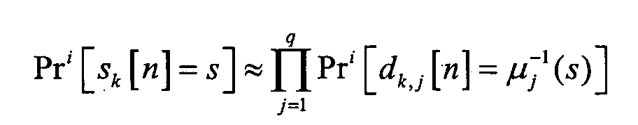
En introduisant le rapport logarithmique π i / k,j[n] des probabilités a priori sur bit
précédemment défini, on peut écrire que :


A partir des vecteurs de données symboliques estimées ![]()
![]()
Un traitement 215 (pouvant comprendre un multiplexage, un démultiplexage, un entrelacement chip, un découpage par blocs), est alors mis en oeuvre.A process 215 (which may include multiplexing, demultiplexing, interleaving chip, a block division), is then implemented.
Le traitement 215 est un traitement conforme à celui appliqué en émission en aval de
l'étalement 108 (voir une des figures 3, 4, 6 et 7).The
Ainsi, par exemple, si le traitement en émission comprenait un simple multiplexage sur les
T antennes d'émission, tel qu'illustré sur les figures 3 et 6, le traitement 215 comprend un
multiplexage sur T voies (illustré sur la figure 10).So, for example, if the broadcast processing included a simple multiplexing on the
Transmitting antennas, as illustrated in FIGS. 3 and 6, the
Ainsi, par exemple, si le traitement en émission comprenait un multiplexage 109 sur une
voie puis un entrelacement chip 110 et un démultiplexage (111) sur les T antennes
d'émission, tel qu'illustré sur les figures 4 et 7, le traitement 215 en réception comprend un
multiplexage sur une voie, un entrelacement chip et un démultiplexage sur T voies (illustré
sur la figure 9).So, for example, if the transmission processing included a
En sortie du traitement 215, est alors généré (déduit de ![]()
![]()
Dans cette section, on considère un bloc donné d'indice b qui a été émis par l'antenne t, le
traitement étant supposé identique pour tous. L'invention suggère de remplacer la détection
optimale des chips x t [l] (au sens du critère MAP) par une estimation au sens du critère
MMSE (biaisée), dérivée sur la base du modèle à fenêtre glissante, dont la complexité est
polynomiale en les paramètres du système et non plus exponentielle. A chaque itération i,
on calcule en 202 un premier filtre f i / t,l∈ ![]()
![]()
![]()
![]()
Il sera préféré une MSE non conditionnelle pour des raisons de complexité : le premier filtre f i / t est alors invariant dans le temps pour le bloc considéré du canal déterminé (le filtre étant calculé une fois et une seule pour le bloc b de données traité).An unconditional MSE will be preferred for reasons of complexity: the first filter f i / t is then invariant in time for the considered block of the determined channel (the filter being calculated once and only once for the block b of data processed ).
A partir du vecteur des estimées des chips à l'itération i :
![]()
![]()
![]()
![]()
Une estimation d'interférences MAI+ISI est ainsi régénérée en 216, en multipliant ce
dernier vecteur avec ladite matrice de Sylvester H (son calcul est décrit ci-dessus au
chapitre 2.2 ou 2.3).
Le premier filtre (de Wiener) 202 est appliqué au vecteur d'observation obtenu après
soustraction en 201 de cette interférence MAI+ISI régénérée :
Ce premier filtre 202 minimise la MSE non conditionnelle sur l'estimation (biaisée) du chip
x t [l] et peut être aisément dérivé à partir du théorème de la projection orthogonale :
![]()
![]()

![]()
![]()
Pour satisfaire la contrainte d'absence de biais, le filtre doit être multiplié à gauche par le
facteur correctif :
![]()
![]()
On obtient l'expression finale du filtre :
![]()
![]()
Dans une variante, ce filtre peut être remplacé, totalement ou à partir d'une itération i
donnée (i≥1), par sa version filtre adapté mono utilisateur (SUMF) donnée par
![]()
![]()
L'évaluée du chip x t [l] correspond alors, à la sortie du premier filtre 202 à :
![]()
![]()
La variance de MAI+ISI résiduelle plus bruit est alors égale à :
![]()

![]()
Autre variante possible de l'égalisation : En référence à la figure 11b est représentée une
variante quant à la façon de mettre en oeuvre le premier filtrage 202' et la régénération
d'interférences MAI+ISI 210', qui est à comparer au premier filtrage 202 et à la
régénération d'interférences MAI+ISI 210 de la figure 11a (représentant ces deux étapes de
détection comprises dans le schéma de la figure 9 ou 10). Another possible variant of the equalization : With reference to FIG. 11b is represented a variant as to how to implement the first filtering 202 'and the MAI + ISI 210' interference regeneration, which is to be compared to the
En référence à la figure 11b, le premier filtrage 202' se fait ici en amont de la première
soustraction 201 d'interférences MAI+ISI régénérées en 210', et non en aval comme c'est
le cas en référence à la figure 11a.With reference to FIG. 11b, the first filtering 202 'is here upstream of the
Le premier filtre f' utilisé et la matrice de reconstruction d'interférences MAI+ISI notée ici
b1' utilisés peuvent se déduire de façon triviale du premier filtre f et de la matrice de
reconstruction d'interférences MAI+ISI notée ici b1 précédemment calculés (cf ci-dessus en
référence aux figures 9 ou 10, et 11a), à partir de l'égalité suivante :

Pour en déduire alors que :
Les deux cas distingués à l'émission (i.e. étalement spatio-temporel (ou spatio-fréquentiel) , et étalement temporel (ou fréquentiel) ) donnent lieu à 1 ou T modèles d'accès multiple différents.The two cases distinguished on the emission (i.e. spatio-temporal sprawl (or space-frequency), and time (or frequency) spread) give rise to 1 or T multiple access models different.
En référence aux figures 9 et 10, les matrices de chips X and i(1), ..., X and i(B) sont ici regroupées en
une unique matrice X and, elle-même réorganisée, après traitement 203, en une unique matrice
Z and i de dimension N×L ; le traitement 203 correspondant à l'inverse du traitement 215 décrit
dans 5.2. With reference to FIGS. 9 and 10, the chips matrices X and i (1) ,..., X and i ( B ) are here grouped into a single matrix X and , itself reorganized, after
On obtient alors un modèle d'accès multiple (canonique) gaussien équivalent du type :
La matrice des chips observés est notée :

La matrice des échantillons de bruit dans le temps est notée :

Pour chaque instant n, on pose :

Pour simplifier les traitements qui suivent (détection multiutilisateur MMSE), on peut
supposer une variance des échantillons de bruit constante pour l'ensemble du système :

On élimine alors la dépendance temporelle :
Comme vu précédemment, lorsque l'étalement est périodique, un entrelaceur chip (110) a
été mis en oeuvre à l'émission, si bien que le traitement 203 inclut un désentrelacement chip
en référence à la figure 9.As seen previously, when the spreading is periodic, a chip interleaver (110) has
been implemented on the program, so that the
On remplace ici la détection optimale des symboles s k [n] (au sens du critère MAP) par une
évaluation MMSE non biaisée, dont la complexité est polynomiale en les paramètres du
système et non exponentielle. A chaque itération i, pour chaque utilisateur potentiel k, on
calcule en 204 un deuxième filtre g i / k,n ∈ ![]()
![]()
![]()
![]()
A partir du vecteur des estimées des symboles à l'itération i :
![]()
![]()
![]()
![]()
Une estimation d'interférences MUI est ainsi régénérée en 213, en multipliant ce dernier
vecteur avec la matrice d'étalement W utilisée à l'émission :
![]()
![]()
Le deuxième filtre (de Wiener, biaisé) est alors appliqué en 205 au vecteur d'observation
obtenu après soustraction 204 de cette interférence MUI régénérée :
![]()
![]()
Ce deuxième filtre 205 minimise la MSE non conditionnelle sur l'estimation du symbole
s k [n] et peut être aisément dérivé à partir du théorème de la projection orthogonale :
où :
![]()

![]()
or : ![]()
![]()
Pour satisfaire la contrainte d'absence de biais, le deuxième filtre doit être multiplié à
gauche par le facteur correctif :
![]()
![]()
On obtient alors l'expression finale du deuxième filtre :
![]()
![]()
L'évaluée du symbole s k [n] correspond à la sortie du deuxième filtre 205 à :
![]()
![]()
La variance du terme d'interférences MUI résiduelles plus bruit ξ i k [n] peut être évaluée via
l'estimateur consistant en :

Dans une version simplifiée, on peut remplacer en 205 le deuxième filtre MMSE à partir
d'une itération quelconque i par un deuxième filtre SUMF :
On obtient l'évaluée :
![]()
![]()
Cette approche permet d'éviter le calcul des matrices inverses de dimension N x N. This approach makes it possible to avoid the computation of inverse matrices of dimension N x N.
Dans le cas non surchargé, on a :
La détection se résume à appliquer en 205 le deuxième filtre g i / k = e † / kW† au vecteur d'observation.The detection amounts to applying in 205 the second filter g i / k = e † / k W † to the observation vector.
On obtient alors directement l'évaluée par :
![]()
![]()
Dans ce cas, le traitement 203 peut ou non inclure un desentrelacement chip en référence
aux figures 9 et 10. Le modèle d'accès multiple (canonique) gaussien équivalent s'écrit
maintenant :
Seules les détections du type SUMF sont de complexité raisonnable dans le cas apériodique, et seront donc préférentiellement mis en oeuvre.Only SUMF type detections are of reasonable complexity in the case aperiodic, and will therefore preferably be implemented.
Le filtre a alors l'expression suivante : g i k = {e† k W† nWne k } -1 e† k W† n The filter then has the following expression: g i k = {e † k W † n W n e k } - 1 e † k W † n
Le filtre a alors l'expression suivante :
Les matrices de chips X and i(1),...,X and i(B) sont regroupées en une unique matrice X and. Après le
traitement 203, et en référence aux figures 9 et 10, X and est réorganisée en T matrices
Z and i(1),..., Z and i(T) de dimension S F × L correspondant à T modèles d'accès multiple
(canoniques) gaussiens équivalents indépendants du type :
La matrice des chips observés est notée :

La matrice des échantillons de bruit décorrélés dans le temps :

Pour chaque instant, on pose :

Pour simplifier les traitements qui suivent (détection multiutilisateur MMSE), on peut
supposer une variance des échantillons de bruit constante pour l'ensemble du système :

On élimine alors la dépendance temporelle :
Les calculs des filtres g i(t) / u par modèle d'accès multiple étant similaires au cas précédent, ceux-ci ne seront pas explicités.The calculations of the filters g i ( t ) / u by multiple access model being similar to the previous case, these will not be explained.
Comme vu précédemment, lorsque l'étalement est périodique, un entrelaceur chip (110) a
été mis en oeuvre à l'émission, si bien que le traitement 203 inclut un désentrelacement chip
en référence à la figure 9.As seen previously, when the spreading is periodic, a chip interleaver (110) has
been implemented on the program, so that the
Le filtre a alors l'expression suivante :
![]()
![]()
A partir d'une itération i quelconque, le filtre MMSE peut être remplacé par sa version sous
optimale SUMF
![]()
![]()
Le filtre a alors l'expression suivante :
Dans ce cas, le traitement 203 peut ou non inclure un désentrelacement chip en référence
aux figures 9 et 10. Les T modèles d'accès multiple (canonique) gaussien équivalent
s'écrivent maintenant :
Seules les détections du type SUMF sont de complexité raisonnable dans le cas apériodique.Only SUMF type detections are of reasonable complexity in the case aperiodic.
Le filtre a alors l'expression suivante :
![]()
![]()
Le filtre a alors l'expression suivante :
Autre variante possible de l'égalisation : Quels que soient les cas déclinés aux chapitres
5.4.1 et 5.4.2, il existe aussi une variante quant à la façon de mettre en oeuvre le deuxième
filtrage 205' et la régénération d'interférences MUI 213' (en référence à la figure 12b), qui
est à comparer au deuxième filtrage 205 et à la régénération d'interférences MUI 213 de la
figure 12a (représentant ces deux étapes de détection comprise dans le schéma de la figure
9 ou 10). Another possible variant of the equalization : Whatever the cases described in chapters 5.4.1 and 5.4.2, there is also a variant as to how to implement the second filtering 205 'and the regeneration of
En référence à la figure 12b, le deuxième filtrage 205' se fait ici en amont de la deuxième
soustraction 204 d'interférences régénérées en 213', et non en aval comme c'est le cas en
référence à la figure 12a. With reference to FIG. 12b, the second filtering 205 'is here upstream of the
Le deuxième filtre g' utilisé et la matrice de reconstruction b2' d'interférences MUI utilisés
peuvent se déduire de façon triviale du deuxième filtre g et de la matrice de reconstruction
b2 d'interférences MUI précédemment calculés (cf ci-dessus en référence aux figures 9 ou
10, et 12a), à partir de l'égalité suivante :

Pour en déduire alors :
Sur la base des sorties du deuxième filtrage linéaire 205 à K filtres, q rapport logarithmique
de probabilité a posteriori (APP) sont calculés en 206 pour chaque symbole à chaque
instant n = 0, ..., L-1, pour chaque utilisateur k = 1, ..., K. Ces quantités probabilistes sont
définies comme :

Soit encore :

![]()
Let's still: ![]()
Le développement du numérateur et du dénominateur donne :

Les vraisemblances s'expriment comme :

A chaque itération i, une information a priori sur les bits des différents symboles, en
provenance du ou des décodeurs de canal 209, est disponible et exploitable sous la forme de
rapports logarithmiques de probabilité a priori, préalablement introduits et dont on rappelle
l'expression :
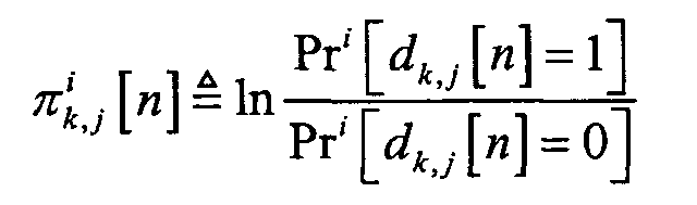
En supposant un entrelacement spatio-temporel de profondeur suffisamment grande, on
peut écrire :

L'information extrinsèque sur chaque bit délivrée par les démodulateurs 206 à sortie
pondérée à destination du décodeur de canal 209 est alors trouvée en 207 par :
![]()
![]()
Tous les rapports logarithmiques d'information extrinsèque sur bits sont ensuite collectés
pour tous les blocs, puis proprement multiplexés et désentrelacés au niveau binaire en 208,
à destination du décodeur de canal 209.All log reports of extrinsic bit information are then collected
for all the blocks, then properly multiplexed and deinterleaved at the binary level at 208,
to the
Le décodeur 209 observe un unique vecteur ϕ i ∈ ![]()
![]()
Cette algorithmique λ est la base sur laquelle sont calculés en 210a et en 210b les rapports
logarithmiques d'information extrinsèque sur bit après décodage, formellement définis
∀l = 1, ..., N o comme :

Les rapports logarithmiques d'information extrinsèque sur bits de mot de code
![]()
![]()
![]()
![]()
La réception selon l'invention concerne non seulement un procédé permettant sa mise en oeuvre, mais aussi le système apte à l'exécuter, ainsi que tout le système de transmission intégrant ce système de réception.The reception according to the invention concerns not only a method enabling its implementation the system capable of executing it, as well as the entire transmission system integrating this receiving system.
Claims (33)
Priority Applications (9)
| Application Number | Priority Date | Filing Date | Title |
|---|---|---|---|
| EP04291039A EP1589685B1 (en) | 2004-04-22 | 2004-04-22 | Iterative chip equalization and multiuser detection for CDMA communications systems on MIMO channels |
| AT04291039T ATE408280T1 (en) | 2004-04-22 | 2004-04-22 | ITERATIVE CHIP DISTORTION AND MULTI-USER DETECTION IN CDMA COMMUNICATION SYSTEMS THROUGH MIMO CHANNEL |
| DE602004016457T DE602004016457D1 (en) | 2004-04-22 | 2004-04-22 | Iterative Chip Equalization and Multi-User Detection in CDMA Communication Systems by MIMO Channel |
| ES04291039T ES2312937T3 (en) | 2004-04-22 | 2004-04-22 | ELEMENT OF ITERATIVE SEPARATE MULTI-USER EQUALIZATION AND DETECTION CODE FOR CDMA COMMUNICATION SYSTEMS ON MIMO CHANNEL. |
| US11/587,223 US7809045B2 (en) | 2004-04-22 | 2005-04-21 | Disjoint iterative chip equalization and multi-user detection for CDMA communication system on a MIMO channel |
| CN2005800205585A CN1973475B (en) | 2004-04-22 | 2005-04-21 | Receiving method and system for communication through frequency-selective channels with multiple transmitting antennas and receiving antenas |
| JP2007508865A JP4754556B2 (en) | 2004-04-22 | 2005-04-21 | Independent repetitive chip equalization and multi-user detection for CDMA communication systems over MIMO channels |
| PCT/EP2005/004410 WO2005114887A1 (en) | 2004-04-22 | 2005-04-21 | Disjoint iterative chip equalisation and multi-user detection for cdma communication systems on a mimo channel |
| KR1020067024371A KR101121978B1 (en) | 2004-04-22 | 2006-11-21 | Disjoint iterative chip equalisation and multi-user detection for cdma communication systems on a mimo channel |
Applications Claiming Priority (1)
| Application Number | Priority Date | Filing Date | Title |
|---|---|---|---|
| EP04291039A EP1589685B1 (en) | 2004-04-22 | 2004-04-22 | Iterative chip equalization and multiuser detection for CDMA communications systems on MIMO channels |
Publications (2)
| Publication Number | Publication Date |
|---|---|
| EP1589685A1 true EP1589685A1 (en) | 2005-10-26 |
| EP1589685B1 EP1589685B1 (en) | 2008-09-10 |
Family
ID=34931045
Family Applications (1)
| Application Number | Title | Priority Date | Filing Date |
|---|---|---|---|
| EP04291039A Expired - Lifetime EP1589685B1 (en) | 2004-04-22 | 2004-04-22 | Iterative chip equalization and multiuser detection for CDMA communications systems on MIMO channels |
Country Status (9)
| Country | Link |
|---|---|
| US (1) | US7809045B2 (en) |
| EP (1) | EP1589685B1 (en) |
| JP (1) | JP4754556B2 (en) |
| KR (1) | KR101121978B1 (en) |
| CN (1) | CN1973475B (en) |
| AT (1) | ATE408280T1 (en) |
| DE (1) | DE602004016457D1 (en) |
| ES (1) | ES2312937T3 (en) |
| WO (1) | WO2005114887A1 (en) |
Families Citing this family (13)
| Publication number | Priority date | Publication date | Assignee | Title |
|---|---|---|---|---|
| ES2312937T3 (en) * | 2004-04-22 | 2009-03-01 | France Telecom | ELEMENT OF ITERATIVE SEPARATE MULTI-USER EQUALIZATION AND DETECTION CODE FOR CDMA COMMUNICATION SYSTEMS ON MIMO CHANNEL. |
| EP1589673B1 (en) * | 2004-04-22 | 2014-06-04 | Orange | Iterative multiuser detection method for CDMA communications systems on MIMO canal |
| WO2006099267A2 (en) * | 2005-03-14 | 2006-09-21 | Telcordia Technologies, Inc. | Iterative mimo receiver using group-wise demapping |
| CN100444543C (en) * | 2006-03-31 | 2008-12-17 | 东南大学 | Airspace filter detecting method for multiple antenna radio communication system |
| KR100845498B1 (en) * | 2006-09-29 | 2008-07-10 | 한국전자통신연구원 | Apparatus and method for precoder in multiuser MIMO system |
| US8358716B2 (en) * | 2009-03-06 | 2013-01-22 | Massachusetts Institute Of Technology | Method and apparatus for synchronizing a wireless communication system |
| WO2010096329A2 (en) * | 2009-02-18 | 2010-08-26 | Massachusetts Institute Of Technology | Method and apparatus for synchronizing a wireless communication system |
| WO2011120215A1 (en) * | 2010-03-29 | 2011-10-06 | 华为技术有限公司 | Data processing method, system and receiver |
| CN102035568B (en) | 2010-11-05 | 2014-05-28 | 意法·爱立信半导体(北京)有限公司 | Method and device for eliminating interference in mobile communication system |
| US8792598B1 (en) * | 2011-08-02 | 2014-07-29 | Marvell International Ltd. | Coexistence of multiple communication technologies on a single device |
| CN102271104B (en) * | 2011-09-07 | 2013-09-25 | 中国电信股份有限公司 | Multi-user detection method and device of CDMA (Code Division Multiple Access) network, and multi-user detection filter |
| CN106685866B (en) * | 2015-11-10 | 2020-12-22 | 中兴通讯股份有限公司 | Interference elimination method, device and base station |
| TWI722689B (en) * | 2019-11-29 | 2021-03-21 | 財團法人工業技術研究院 | Detector and interference cancellation method for spatial multiplexing filter bank multicarrier with offset quadrature amplitude modulation |
Citations (3)
| Publication number | Priority date | Publication date | Assignee | Title |
|---|---|---|---|---|
| WO2001019013A1 (en) * | 1999-09-09 | 2001-03-15 | Home Wireless Networks, Inc. | Turbo detection of space-time codes |
| FR2810175A1 (en) * | 2000-06-09 | 2001-12-14 | Thomson Csf | High rate data transmission system using BLAST coding, has space-time encoder and several modulators-transmitters |
| FR2841068A1 (en) * | 2002-06-14 | 2003-12-19 | Comsis | Decoding linear space-time codes in multiple-antenna wireless transmission system, used in digital radio data distribution over local wireless network, uses matrices to remove interference caused by multiple propagation across ionosphere |
Family Cites Families (14)
| Publication number | Priority date | Publication date | Assignee | Title |
|---|---|---|---|---|
| US6785323B1 (en) | 1999-11-22 | 2004-08-31 | Ipr Licensing, Inc. | Variable rate coding for forward link |
| FR2809249B1 (en) * | 2000-05-16 | 2004-04-23 | France Telecom | METHOD AND SYSTEM FOR ITERATIVE DETECTION AND DECODING OF RECEIVED SYMBOLS, COUPLED TO A REESTIMATION OF THE TRANSMISSION CHANNEL COEFFICIENTS |
| US7154958B2 (en) * | 2000-07-05 | 2006-12-26 | Texas Instruments Incorporated | Code division multiple access wireless system with time reversed space time block transmitter diversity |
| JP3714910B2 (en) * | 2001-02-20 | 2005-11-09 | 株式会社エヌ・ティ・ティ・ドコモ | Turbo receiving method and receiver thereof |
| FR2821217B1 (en) * | 2001-02-21 | 2003-04-25 | France Telecom | METHOD AND SYSTEM FOR ITERATIVE CODING-DECODING OF DIGITAL DATA STREAMS ENCODED BY SPATIO-TEMPORAL COMBINATIONS, IN MULTIPLE TRANSMISSION AND RECEPTION |
| EP1335518B1 (en) * | 2002-01-31 | 2005-11-09 | Motorola, Inc. | Reception of multicarrier spread-spectrum signals |
| US20040116077A1 (en) * | 2002-08-08 | 2004-06-17 | Kddi Corporation | Transmitter device and receiver device adopting space time transmit diversity multicarrier CDMA, and wireless communication system with the transmitter device and the receiver device |
| JP4412926B2 (en) * | 2002-09-27 | 2010-02-10 | 株式会社エヌ・ティ・ティ・ドコモ | Adaptive equalization apparatus and program thereof |
| JP3669991B2 (en) * | 2003-02-18 | 2005-07-13 | 三星電子株式会社 | Wireless transceiver, wireless transmission / reception method and program thereof |
| CN100479338C (en) * | 2003-03-03 | 2009-04-15 | 美商内数位科技公司 | Reduced complexity sliding window based equalizer |
| CN1188975C (en) * | 2003-03-21 | 2005-02-09 | 清华大学 | Space-time iterative multiuser detecting algorithm based on soft sensitive bit and space grouping |
| FI20040182A0 (en) * | 2004-02-06 | 2004-02-06 | Nokia Corp | Data processing method, equalizer and receiver |
| EP1589672B1 (en) * | 2004-04-22 | 2014-06-04 | Orange | Iterative vectorized equalization method for CDMA communications systems on MIMO channel |
| ES2312937T3 (en) * | 2004-04-22 | 2009-03-01 | France Telecom | ELEMENT OF ITERATIVE SEPARATE MULTI-USER EQUALIZATION AND DETECTION CODE FOR CDMA COMMUNICATION SYSTEMS ON MIMO CHANNEL. |
-
2004
- 2004-04-22 ES ES04291039T patent/ES2312937T3/en not_active Expired - Lifetime
- 2004-04-22 EP EP04291039A patent/EP1589685B1/en not_active Expired - Lifetime
- 2004-04-22 DE DE602004016457T patent/DE602004016457D1/en not_active Expired - Lifetime
- 2004-04-22 AT AT04291039T patent/ATE408280T1/en not_active IP Right Cessation
-
2005
- 2005-04-21 CN CN2005800205585A patent/CN1973475B/en active Active
- 2005-04-21 WO PCT/EP2005/004410 patent/WO2005114887A1/en active Application Filing
- 2005-04-21 US US11/587,223 patent/US7809045B2/en active Active
- 2005-04-21 JP JP2007508865A patent/JP4754556B2/en active Active
-
2006
- 2006-11-21 KR KR1020067024371A patent/KR101121978B1/en active IP Right Grant
Patent Citations (3)
| Publication number | Priority date | Publication date | Assignee | Title |
|---|---|---|---|---|
| WO2001019013A1 (en) * | 1999-09-09 | 2001-03-15 | Home Wireless Networks, Inc. | Turbo detection of space-time codes |
| FR2810175A1 (en) * | 2000-06-09 | 2001-12-14 | Thomson Csf | High rate data transmission system using BLAST coding, has space-time encoder and several modulators-transmitters |
| FR2841068A1 (en) * | 2002-06-14 | 2003-12-19 | Comsis | Decoding linear space-time codes in multiple-antenna wireless transmission system, used in digital radio data distribution over local wireless network, uses matrices to remove interference caused by multiple propagation across ionosphere |
Non-Patent Citations (1)
| Title |
|---|
| BERTHET A O ET AL: "ITERATIVE DECODING OF SERIALLY CONCATENATED MULTILAYERED TRELLIS-CODED MODULATIONS IN THE PRESENCE OF INTERSYMBOL INTERFERENCE AND NOISE", GLOBECOM'01. 2001 IEEE GLOBAL TELECOMMUNICATIONS CONFERENCE. SAN ANTONIO, TX, NOV. 25 - 29, 2001, IEEE GLOBAL TELECOMMUNICATIONS CONFERENCE, NEW YORK, NY : IEEE, US, vol. VOL. 2 OF 6, 25 November 2001 (2001-11-25), pages 1042 - 1047, XP001099264, ISBN: 0-7803-7206-9 * |
Also Published As
| Publication number | Publication date |
|---|---|
| WO2005114887A1 (en) | 2005-12-01 |
| JP4754556B2 (en) | 2011-08-24 |
| KR101121978B1 (en) | 2012-03-09 |
| CN1973475A (en) | 2007-05-30 |
| KR20070017385A (en) | 2007-02-09 |
| EP1589685B1 (en) | 2008-09-10 |
| ATE408280T1 (en) | 2008-09-15 |
| JP2007534245A (en) | 2007-11-22 |
| US20070217386A1 (en) | 2007-09-20 |
| DE602004016457D1 (en) | 2008-10-23 |
| CN1973475B (en) | 2011-06-01 |
| ES2312937T3 (en) | 2009-03-01 |
| US7809045B2 (en) | 2010-10-05 |
Similar Documents
| Publication | Publication Date | Title |
|---|---|---|
| WO2005114887A1 (en) | Disjoint iterative chip equalisation and multi-user detection for cdma communication systems on a mimo channel | |
| EP1658694B1 (en) | Iterative decoding and equalizion method and apparatus for communication with multiple transmission and reception antennas | |
| EP2947799B1 (en) | Method of widely linear turbo-equalisation in a multi-user system and for a multi-antenna receiver | |
| WO2005114864A1 (en) | Iterative vector equalisation for cdma communications systems on the mimo channel | |
| JP2007534245A5 (en) | ||
| EP1391095B1 (en) | Method for estimating the transfer function of a multicarrier signal transmission channel and corresponding receiver | |
| WO2005114863A1 (en) | Multi-user iterative detection for cdma communications systems on the mimo channel | |
| EP1920547A1 (en) | Interference reduction in a communication signal | |
| EP1603264B1 (en) | Method and system for receiving a linearly precoded and channel coded signal | |
| EP3800813B1 (en) | Method and device for predicting the performance of a receiver in a communication system | |
| EP3528443B1 (en) | Method for calculating an estimate of a modulated digital signal and its reliability | |
| WO2007028917A2 (en) | Iterative estimation for mimo channel in a cdma network | |
| EP1999918B1 (en) | Method and device for receiving a data signal consisting of symbol blocks and corresponding computer program | |
| EP1221206B1 (en) | Method and device for demodulating signals from multiusers | |
| FR2849306A1 (en) | Digital word packet radio propagation compensation having iterative feedback estimator/symbol detector with operations providing distinct channel estimates/removing word groups received dependent transmission conditions | |
| WO2016020611A1 (en) | Method and device for receiving signals |
Legal Events
| Date | Code | Title | Description |
|---|---|---|---|
| PUAI | Public reference made under article 153(3) epc to a published international application that has entered the european phase |
Free format text: ORIGINAL CODE: 0009012 |
|
| AK | Designated contracting states |
Kind code of ref document: A1 Designated state(s): AT BE BG CH CY CZ DE DK EE ES FI FR GB GR HU IE IT LI LU MC NL PL PT RO SE SI SK TR |
|
| AX | Request for extension of the european patent |
Extension state: AL HR LT LV MK |
|
| AKX | Designation fees paid | ||
| 17P | Request for examination filed |
Effective date: 20060627 |
|
| RBV | Designated contracting states (corrected) |
Designated state(s): AT BE BG CH CY CZ DE DK EE ES FI FR GB GR HU IE IT LI LU MC NL PL PT RO SE SI SK TR |
|
| REG | Reference to a national code |
Ref country code: DE Ref legal event code: 8566 |
|
| 17Q | First examination report despatched |
Effective date: 20061018 |
|
| GRAP | Despatch of communication of intention to grant a patent |
Free format text: ORIGINAL CODE: EPIDOSNIGR1 |
|
| RIN1 | Information on inventor provided before grant (corrected) |
Inventor name: VISOZ, RAPHAEL Inventor name: BERTHET, ANTOINE |
|
| GRAS | Grant fee paid |
Free format text: ORIGINAL CODE: EPIDOSNIGR3 |
|
| GRAA | (expected) grant |
Free format text: ORIGINAL CODE: 0009210 |
|
| AK | Designated contracting states |
Kind code of ref document: B1 Designated state(s): AT BE BG CH CY CZ DE DK EE ES FI FR GB GR HU IE IT LI LU MC NL PL PT RO SE SI SK TR |
|
| REG | Reference to a national code |
Ref country code: GB Ref legal event code: FG4D Free format text: NOT ENGLISH |
|
| REG | Reference to a national code |
Ref country code: CH Ref legal event code: EP |
|
| REG | Reference to a national code |
Ref country code: IE Ref legal event code: FG4D Free format text: LANGUAGE OF EP DOCUMENT: FRENCH |
|
| REF | Corresponds to: |
Ref document number: 602004016457 Country of ref document: DE Date of ref document: 20081023 Kind code of ref document: P |
|
| PG25 | Lapsed in a contracting state [announced via postgrant information from national office to epo] |
Ref country code: AT Free format text: LAPSE BECAUSE OF FAILURE TO SUBMIT A TRANSLATION OF THE DESCRIPTION OR TO PAY THE FEE WITHIN THE PRESCRIBED TIME-LIMIT Effective date: 20080910 Ref country code: FI Free format text: LAPSE BECAUSE OF FAILURE TO SUBMIT A TRANSLATION OF THE DESCRIPTION OR TO PAY THE FEE WITHIN THE PRESCRIBED TIME-LIMIT Effective date: 20080910 Ref country code: SI Free format text: LAPSE BECAUSE OF FAILURE TO SUBMIT A TRANSLATION OF THE DESCRIPTION OR TO PAY THE FEE WITHIN THE PRESCRIBED TIME-LIMIT Effective date: 20080910 |
|
| REG | Reference to a national code |
Ref country code: ES Ref legal event code: FG2A Ref document number: 2312937 Country of ref document: ES Kind code of ref document: T3 |
|
| NLV1 | Nl: lapsed or annulled due to failure to fulfill the requirements of art. 29p and 29m of the patents act | ||
| REG | Reference to a national code |
Ref country code: IE Ref legal event code: FD4D |
|
| PG25 | Lapsed in a contracting state [announced via postgrant information from national office to epo] |
Ref country code: BG Free format text: LAPSE BECAUSE OF FAILURE TO SUBMIT A TRANSLATION OF THE DESCRIPTION OR TO PAY THE FEE WITHIN THE PRESCRIBED TIME-LIMIT Effective date: 20081210 Ref country code: IE Free format text: LAPSE BECAUSE OF FAILURE TO SUBMIT A TRANSLATION OF THE DESCRIPTION OR TO PAY THE FEE WITHIN THE PRESCRIBED TIME-LIMIT Effective date: 20080910 |
|
| PG25 | Lapsed in a contracting state [announced via postgrant information from national office to epo] |
Ref country code: SK Free format text: LAPSE BECAUSE OF FAILURE TO SUBMIT A TRANSLATION OF THE DESCRIPTION OR TO PAY THE FEE WITHIN THE PRESCRIBED TIME-LIMIT Effective date: 20080910 Ref country code: RO Free format text: LAPSE BECAUSE OF FAILURE TO SUBMIT A TRANSLATION OF THE DESCRIPTION OR TO PAY THE FEE WITHIN THE PRESCRIBED TIME-LIMIT Effective date: 20080910 Ref country code: NL Free format text: LAPSE BECAUSE OF FAILURE TO SUBMIT A TRANSLATION OF THE DESCRIPTION OR TO PAY THE FEE WITHIN THE PRESCRIBED TIME-LIMIT Effective date: 20080910 Ref country code: PT Free format text: LAPSE BECAUSE OF FAILURE TO SUBMIT A TRANSLATION OF THE DESCRIPTION OR TO PAY THE FEE WITHIN THE PRESCRIBED TIME-LIMIT Effective date: 20090210 Ref country code: CZ Free format text: LAPSE BECAUSE OF FAILURE TO SUBMIT A TRANSLATION OF THE DESCRIPTION OR TO PAY THE FEE WITHIN THE PRESCRIBED TIME-LIMIT Effective date: 20080910 |
|
| PLBE | No opposition filed within time limit |
Free format text: ORIGINAL CODE: 0009261 |
|
| STAA | Information on the status of an ep patent application or granted ep patent |
Free format text: STATUS: NO OPPOSITION FILED WITHIN TIME LIMIT |
|
| PG25 | Lapsed in a contracting state [announced via postgrant information from national office to epo] |
Ref country code: DK Free format text: LAPSE BECAUSE OF FAILURE TO SUBMIT A TRANSLATION OF THE DESCRIPTION OR TO PAY THE FEE WITHIN THE PRESCRIBED TIME-LIMIT Effective date: 20080910 Ref country code: EE Free format text: LAPSE BECAUSE OF FAILURE TO SUBMIT A TRANSLATION OF THE DESCRIPTION OR TO PAY THE FEE WITHIN THE PRESCRIBED TIME-LIMIT Effective date: 20080910 |
|
| 26N | No opposition filed |
Effective date: 20090611 |
|
| BERE | Be: lapsed |
Owner name: FRANCE TELECOM Effective date: 20090430 |
|
| REG | Reference to a national code |
Ref country code: CH Ref legal event code: PL |
|
| PG25 | Lapsed in a contracting state [announced via postgrant information from national office to epo] |
Ref country code: SE Free format text: LAPSE BECAUSE OF FAILURE TO SUBMIT A TRANSLATION OF THE DESCRIPTION OR TO PAY THE FEE WITHIN THE PRESCRIBED TIME-LIMIT Effective date: 20081210 Ref country code: LI Free format text: LAPSE BECAUSE OF NON-PAYMENT OF DUE FEES Effective date: 20090430 Ref country code: CH Free format text: LAPSE BECAUSE OF NON-PAYMENT OF DUE FEES Effective date: 20090430 |
|
| PG25 | Lapsed in a contracting state [announced via postgrant information from national office to epo] |
Ref country code: MC Free format text: LAPSE BECAUSE OF NON-PAYMENT OF DUE FEES Effective date: 20090430 |
|
| PG25 | Lapsed in a contracting state [announced via postgrant information from national office to epo] |
Ref country code: PL Free format text: LAPSE BECAUSE OF FAILURE TO SUBMIT A TRANSLATION OF THE DESCRIPTION OR TO PAY THE FEE WITHIN THE PRESCRIBED TIME-LIMIT Effective date: 20080910 Ref country code: BE Free format text: LAPSE BECAUSE OF NON-PAYMENT OF DUE FEES Effective date: 20090430 |
|
| PG25 | Lapsed in a contracting state [announced via postgrant information from national office to epo] |
Ref country code: GR Free format text: LAPSE BECAUSE OF FAILURE TO SUBMIT A TRANSLATION OF THE DESCRIPTION OR TO PAY THE FEE WITHIN THE PRESCRIBED TIME-LIMIT Effective date: 20081211 |
|
| PG25 | Lapsed in a contracting state [announced via postgrant information from national office to epo] |
Ref country code: LU Free format text: LAPSE BECAUSE OF NON-PAYMENT OF DUE FEES Effective date: 20090422 |
|
| PG25 | Lapsed in a contracting state [announced via postgrant information from national office to epo] |
Ref country code: HU Free format text: LAPSE BECAUSE OF FAILURE TO SUBMIT A TRANSLATION OF THE DESCRIPTION OR TO PAY THE FEE WITHIN THE PRESCRIBED TIME-LIMIT Effective date: 20090311 |
|
| PG25 | Lapsed in a contracting state [announced via postgrant information from national office to epo] |
Ref country code: TR Free format text: LAPSE BECAUSE OF FAILURE TO SUBMIT A TRANSLATION OF THE DESCRIPTION OR TO PAY THE FEE WITHIN THE PRESCRIBED TIME-LIMIT Effective date: 20080910 |
|
| PG25 | Lapsed in a contracting state [announced via postgrant information from national office to epo] |
Ref country code: CY Free format text: LAPSE BECAUSE OF FAILURE TO SUBMIT A TRANSLATION OF THE DESCRIPTION OR TO PAY THE FEE WITHIN THE PRESCRIBED TIME-LIMIT Effective date: 20080910 |
|
| REG | Reference to a national code |
Ref country code: FR Ref legal event code: PLFP Year of fee payment: 13 |
|
| REG | Reference to a national code |
Ref country code: FR Ref legal event code: PLFP Year of fee payment: 14 |
|
| REG | Reference to a national code |
Ref country code: FR Ref legal event code: PLFP Year of fee payment: 15 |
|
| PGFP | Annual fee paid to national office [announced via postgrant information from national office to epo] |
Ref country code: FR Payment date: 20230321 Year of fee payment: 20 |
|
| PGFP | Annual fee paid to national office [announced via postgrant information from national office to epo] |
Ref country code: IT Payment date: 20230322 Year of fee payment: 20 Ref country code: GB Payment date: 20230321 Year of fee payment: 20 |
|
| PGFP | Annual fee paid to national office [announced via postgrant information from national office to epo] |
Ref country code: ES Payment date: 20230502 Year of fee payment: 20 Ref country code: DE Payment date: 20230321 Year of fee payment: 20 |
|
| REG | Reference to a national code |
Ref country code: DE Ref legal event code: R071 Ref document number: 602004016457 Country of ref document: DE |
|
| REG | Reference to a national code |
Ref country code: ES Ref legal event code: FD2A Effective date: 20240429 |
|
| REG | Reference to a national code |
Ref country code: GB Ref legal event code: PE20 Expiry date: 20240421 |
|
| PG25 | Lapsed in a contracting state [announced via postgrant information from national office to epo] |
Ref country code: GB Free format text: LAPSE BECAUSE OF EXPIRATION OF PROTECTION Effective date: 20240421 |
|
| PG25 | Lapsed in a contracting state [announced via postgrant information from national office to epo] |
Ref country code: ES Free format text: LAPSE BECAUSE OF EXPIRATION OF PROTECTION Effective date: 20240423 |
|
| PG25 | Lapsed in a contracting state [announced via postgrant information from national office to epo] |
Ref country code: GB Free format text: LAPSE BECAUSE OF EXPIRATION OF PROTECTION Effective date: 20240421 Ref country code: ES Free format text: LAPSE BECAUSE OF EXPIRATION OF PROTECTION Effective date: 20240423 |