EP1589679B1 - Optical transmission method and optical transmission device - Google Patents
Optical transmission method and optical transmission device Download PDFInfo
- Publication number
- EP1589679B1 EP1589679B1 EP04704719A EP04704719A EP1589679B1 EP 1589679 B1 EP1589679 B1 EP 1589679B1 EP 04704719 A EP04704719 A EP 04704719A EP 04704719 A EP04704719 A EP 04704719A EP 1589679 B1 EP1589679 B1 EP 1589679B1
- Authority
- EP
- European Patent Office
- Prior art keywords
- optical
- pulse
- time
- dispersion
- transmission
- Prior art date
- Legal status (The legal status is an assumption and is not a legal conclusion. Google has not performed a legal analysis and makes no representation as to the accuracy of the status listed.)
- Expired - Fee Related
Links
Images


Classifications
-
- H—ELECTRICITY
- H04—ELECTRIC COMMUNICATION TECHNIQUE
- H04B—TRANSMISSION
- H04B10/00—Transmission systems employing electromagnetic waves other than radio-waves, e.g. infrared, visible or ultraviolet light, or employing corpuscular radiation, e.g. quantum communication
- H04B10/25—Arrangements specific to fibre transmission
- H04B10/2507—Arrangements specific to fibre transmission for the reduction or elimination of distortion or dispersion
- H04B10/2513—Arrangements specific to fibre transmission for the reduction or elimination of distortion or dispersion due to chromatic dispersion
- H04B10/25137—Arrangements specific to fibre transmission for the reduction or elimination of distortion or dispersion due to chromatic dispersion using pulse shaping at the transmitter, e.g. pre-chirping or dispersion supported transmission [DST]
-
- H—ELECTRICITY
- H04—ELECTRIC COMMUNICATION TECHNIQUE
- H04B—TRANSMISSION
- H04B10/00—Transmission systems employing electromagnetic waves other than radio-waves, e.g. infrared, visible or ultraviolet light, or employing corpuscular radiation, e.g. quantum communication
- H04B10/25—Arrangements specific to fibre transmission
- H04B10/2507—Arrangements specific to fibre transmission for the reduction or elimination of distortion or dispersion
- H04B10/2513—Arrangements specific to fibre transmission for the reduction or elimination of distortion or dispersion due to chromatic dispersion
- H04B10/25133—Arrangements specific to fibre transmission for the reduction or elimination of distortion or dispersion due to chromatic dispersion including a lumped electrical or optical dispersion compensator
-
- H—ELECTRICITY
- H04—ELECTRIC COMMUNICATION TECHNIQUE
- H04B—TRANSMISSION
- H04B10/00—Transmission systems employing electromagnetic waves other than radio-waves, e.g. infrared, visible or ultraviolet light, or employing corpuscular radiation, e.g. quantum communication
- H04B10/25—Arrangements specific to fibre transmission
- H04B10/2507—Arrangements specific to fibre transmission for the reduction or elimination of distortion or dispersion
- H04B10/2569—Arrangements specific to fibre transmission for the reduction or elimination of distortion or dispersion due to polarisation mode dispersion [PMD]
Definitions
- the present invention relates to optical transmission methods, and more specifically, to an optical transmission method for simultaneously and completely compensating for waveform distortions in a signal transmitted through an optical fiber including third-order or higher-order dispersion and arbitrary dispersion or polarization-mode dispersion with time variation by means of a Fourier transform.
- Patent document 2 Use of an optical Fourier transform has been suggested to compensate for group delay resulting from polarization-mode dispersion (patent document 2, non-patent document 5).
- patent document 1 JP 2001-111490 A patent document 2 NP 2002-541720 A Non-patent document 1 M. D. Pelusi, Y. Matsui, and A. Suzuki, "Phase modulation of stretched optical pulses for suppression of third-order dispersion effects in fiber transmission," Electron. Lett. Vol. 34, pp. 1675-1677 (1998 ) Non-patent document 2 M. D. Pelusi, Y. Matsui, and A. Suzuki, “Fourth-order dispersion suppression of ultrashort optical pulses by second-order dispersion and cosine phase modulation," Opt.
- Non-patent document 3 T. Yamamoto and M. Nakazawa, "Third- and fourth-order active dispersion compensation with a phase modulator in a terabit-per-second optical time-division multiplexed transmission," Opt. Lett. Vol. 26, pp. 647-649 (2001 )
- Non-patent document 4 M. Nakazawa, T. Yamamoto, and K. R. Tamura, "1.28 Tbit/s - 70 km OTDM transmission using third- and fourth-order simultaneous dispersion compensation with a phase modulator," ECOC 2000, PD. 2.6
- Non-patent document 5 M. Romagnoli, P. Franco, R.
- EP0817409 A2 discloses a method and device for the generation of transform-limited ultra-short optical pulses.
- dispersion compensation by a fiber is easy while simultaneous compensation for wavelength dispersion including third-order dispersion is difficult, because the technique requires matching of a ratio of second-order dispersion to third-order dispersion. If a phase-conjugate element is used, only even-numbered-order dispersion can be compensated for. If pre-transmission dispersion compensation by phase modulation is performed, a precise dispersion value of the whole transmission line must be obtained before phase modulation is adjusted.
- the conventional techniques use a constant amount of dispersion compensation and cannot vary the amount of dispersion compensation dynamically with the dispersion value varying with time. Accordingly, an adaptive equalization scheme has been required.
- the conventional techniques cannot compensate for polarization-mode dispersion.
- a technique according to the present invention compensates for waveform distortions by taking advantage of characteristics in which the spectral profile remains unchanged even if any type of linear distortion occurs in the time domain, to solve these issues all at once.
- an objective of the present invention is to reproduce an original signal waveform with few linear distortions or without linear distortions, by Fourier-transforming the spectral profile of a transmitted optical signal to one bit in the time domain, and to implement substantially distortion-free optical fiber transmission.
- the present invention provides an optical transmission method for performing digital modulation of an optical pulse as a transmission signal at a transmission end, propagating the pulse through an optical fiber transmission line, and converting the pulse to an electric signal by a photoreceiver, wherein an optical Fourier transformer is disposed before the photoreceiver, the optical Fourier transformer switching between the time-domain waveform of the optical pulse and a frequency spectrum thereof on a time-axis, characterized by: using a pulse which has a time-domain waveform equal to an envelope profile of a frequency spectrum in a function form, and is transform-limited in which a product of the full width at half maximum and the frequency spectral width satisfies the Fourier limit condition, as the optical pulse transmitted; taking advantage of the characteristic in which the envelope profile of the frequency spectrum is distortion-free before and after transmission in a linear transmission even if the time-domain waveform is distorted; and the optical Fourier transformer performing Fourier transformation to the time-domain waveform of the signal pulse transmitted through the optical fiber transmission line and distorted, such that
- the present invention enables simultaneous and complete compensation or nearly complete compensation for linear distortions of a time-domain waveform caused by third-order or higher-order dispersion and arbitrary dispersion or polarization-mode dispersion with time variation, which used to be hard to compensate, so that the transmission capacity and transmission distance of optical fiber communication can be increased.
- the present invention also enables practical and economical optical fiber communication to be implemented, eliminating the need for compensating for dispersion of an optical fiber or polarization-mode dispersion precisely.
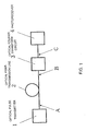
- Fig. 1 shows an embodiment of an optical Fourier transmission system according to the present invention.
- the optical Fourier transmission system includes an optical pulse transmitter 1, an optical fiber transmission line 2, an optical Fourier transform circuit 3, and a photoreceiver 4.
- an optical transmission apparatus includes the optical Fourier transform circuit 3 and the photoreceiver 4.
- the optical pulse transmitter 1 converts an electric signal carrying information to be transmitted into an optical signal, through digital modulation of an optical pulse generated from a light source by an electric signal, and emits a train of optical pulses carrying the information into the optical fiber transmission line 2. It is preferable that the product of the pulse width and the spectral width satisfy the condition of being at the Fourier limit ( ⁇ ⁇ 0.441 for a Gaussian pulse and ⁇ ⁇ 0.315 for a sech pulse, where ⁇ indicates spectral width and ⁇ indicates time-domain pulse width).
- An optical pulse having the best spectral width with respect to the time-domain waveform is called a Fourier-limited pulse (hereafter referred to as a transform-limited pulse). With the transform-limited optical pulse, ideal optical Fourier transmission can be implemented with the best performance.
- the optical fiber transmission line 2 is a transmission line including various kinds of optical fibers having arbitrary dispersion and polarization-mode dispersion. The amounts of these types of dispersion may vary with time.
- the optical Fourier transform circuit 3 receives an optical pulse transmitted through the optical fiber transmission line 2 and Fourier-transforms the pulse train in the time domain to a spectrum in the frequency domain. In high-speed time-division multiplexing, the optical Fourier transform circuit 3 may perform Fourier transform after the signal is demultiplexed to low-rate signals.
- the photoreceiver 4 receives an optical pulse in which dispersion and polarization-mode dispersion caused by the optical fiber transmission line 2 has been compensated for by the optical Fourier transform circuit 3 and converts the pulse into an electric signal.
- the photoreceiver 4 is a PIN, an APD, and any other appropriate photodetector.
- An optical signal transmitted through the optical fiber transmission line 2 is generally an optical time-division multiplexed signal.
- an optical pulse train making up a time-division multiplexed signal is input to the optical Fourier transform circuit 3. Each pulse of the optical pulse train will be described below.
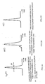
- Fig. 2 shows time-domain waveforms of an optical pulse.
- Figs. 2(a), 2(b), and 2(c) show overviews of the time-domain waveforms of the optical pulse respectively at points A, B, and C of the optical fiber transmission line shown in Fig. 1 .
- Fig. 3 shows the profiles of the frequency spectra of the optical pulse.
- Figs. 3(a), 3(b), and 3(c) show overviews of the frequency spectra of the optical pulse respectively at points A, B, and C of the optical fiber transmission line shown in Fig. 1 .
- the optical pulse transmitter 1 converts an electric signal to an optical pulse, and the optical pulse enters and travels through the optical fiber transmission line 2. It is preferable that the optical pulse transmitter 1 shapes the frequency spectrum U in ( ⁇ ) of the optical pulse ( Fig. 3(a) ), so that the optical pulse has the time-domain waveform u in (t) ( Fig. 2(a) ) of a Fourier-limited pulse (transform-limited pulse) when the pulse enters the optical fiber transmission line 2.
- the optical pulse traveling through the optical fiber transmission line 2 usually undergoes complicated linear distortions resulting from dispersion and polarization-mode dispersion of the optical fiber transmission line 2. These distortions determine the transmission performance of the conventional optical communication.
- the present embodiment allows, as a main feature, the original waveform to be reproduced completely in the frequency domain because the envelope profile of the spectrum input to the optical fiber transmission line 2 is not deformed at all by dispersion and polarization-mode dispersion of the optical fiber transmission line 2.
- the effect of dispersion in an optical fiber is converted to a phase shift in each frequency component of the spectrum, but the photodetector detects just the envelope. Accordingly, the phase shift presents no problem.
- optical Fourier transform circuit reproduces a frequency spectrum U( ⁇ ) ( Fig. 3(b) ) in the time domain, from a time signal u(t) ( Fig. 2(b) ) affected by linear distortions in the optical fiber transmission line 2.
- the time-domain waveform of a transmitted optical pulse goes through the optical Fourier transform circuit 3, and the frequency spectrum of the optical pulse is reproduced in the time domain by replacing time with frequency.
- the optical pulse passing through the optical Fourier transform circuit 3 is converted back to an electric signal by the photoreceiver 4 and is taken out as a signal.
- This optical transmission method is named as "optical Fourier transmission.”
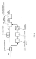
- Fig. 4 shows the configuration of the optical Fourier transform circuit 3.
- the optical Fourier transform circuit 3 includes an optical coupler 5, a clock extraction circuit 6, a phase shifter 7, an electric amplifier 8, a delay fiber 9, a phase modulator 10, and a second-order dispersion element 11.
- phase modulator 10 a phase modulator using the electrooptic effect of LiNbO 3 and others is recommended, for instance.
- the phase modulator 10 may also use the phase modulation effect of electroabsorption (EA) or a semiconductor optical amplifier (SOA). Although many phase modulators 10 have polarization dependence, it is preferable that polarization is eliminated by using a polarization-free optical device or a polarization diversity method.
- the driving frequency of the phase modulator 10 is the pulse transmission rate.
- the optical coupler 5 separates a portion of the transmission signal into two parts, one part to the delay fiber 9 and the other part to the clock extraction circuit 6, so that the phase modulator 10 performs phase modulation in synchronization with the pulse transmitted through the optical fiber transmission line 2.
- the clock extraction circuit 6 extracts a clock signal (a sinusoidal signal) from the transmission signal and drives the phase modulator 10 at the obtained clock frequency through the phase shifter 7 and the electric amplifier 8.
- the phase shifter 7 and the delay fiber 9 function to ensure that optimal phase modulation takes place in synchronization with the optical pulse. If the timing of modulation changes because of a change in temperature, the phase shifter 7 can automatically adjust the amount of the phase shift so that optimum modulation can be performed.
- the electric amplifier 8 outputs a drive signal for driving the phase modulator 10, depending on the output of the phase shifter 7.
- the second-order dispersion element 11 can be a single-mode optical fiber having group velocity dispersion with zero-dispersion region near the 1.3- ⁇ m band, a pair of diffraction gratings, a fiber Bragg grating, a VIPA variable dispersion compensator, an arrayed waveguide grating, a combination of a diffraction grating and a spatial modulator, and others, for instance.
- a stand-alone optical Fourier transform circuit has been originally designed to compensate for group delay caused by polarization-mode dispersion, as described in a paper and others on optical Fourier transform, written by Romagnoli et al. (patent document 2, non-patent document 5).
- the optical Fourier transform circuit is used to compensate for polarization-mode dispersion alone.
- the concept has not reached an idea of performing distortion-free transmission by replacing time with frequency as implemented by the optical Fourier transform circuit 3 of the present embodiment.
- the present invention offers a new principle and technique of optical Fourier transmission that eliminates all linear distortions by converting distortions in the time domain into the spectrum.
- optical Fourier transmission method is used to compensate for waveform distortions of an optical pulse caused by the linear effects of an optical fiber transmission line having arbitrary dispersion and polarization-mode dispersion, in the configuration of the present embodiment.
- pulse propagation in the optical fiber is described by envelope approximation.
- the slowly-varying field envelope amplitude of the pulse is represented as u(z, t); the propagation constant in the medium is represented as ⁇ ( ⁇ ); the frequency of the carrier wave will be represented as ⁇ 0 ; where t is time, z is the position (coordinates) in the longitudinal direction of the optical fiber, and ⁇ is frequency.
- ⁇ 0 , ⁇ 2 ⁇ 2 ⁇ ⁇ ⁇ ⁇ 2 ⁇
- ⁇ 0 , ⁇ 3 ⁇ 3 ⁇ ⁇ ⁇ ⁇ 3 ⁇
- ⁇ 0 , ... , ⁇ n ⁇ n ⁇ ⁇ ⁇ ⁇ n ⁇
- the optical Fourier transform circuit 3 obtains the frequency spectrum U( ⁇ , ⁇ ) from the time-domain waveform u( ⁇ , t) at the receiver side B of the optical fiber transmission line 2 having a length of ⁇ , in the method described below.
- u( ⁇ , t) will be expressed as u(t)
- U( ⁇ , ⁇ ) will be expressed as U( ⁇ ).
- the input waveform of the phase modulator 10 is u(t)
- the output waveform is u'(t) obtained by the equation 13.
- the processing of the phase modulator 10 corresponds to the multiplication of the input waveform u(t) by the phase exp(iKt 2 /2) on the right side of the equation 13.
- the chirp rate K is given to the phase modulator 10 in advance as a parameter. This parameter can be controlled, depending on the magnitude of the voltage applied to the phase modulator.
- the timing of phase modulation and the driving frequency are extracted from and adjusted to the transmission signal, by using the clock extraction circuit 6, the phase shifter 7, and the delay fiber 9.
- v(t) is a signal after propagation through dispersion k"L by the second-order dispersion element 11
- the input waveform of the second-order dispersion element 11 is u' (t) obtained by the equation 13, and the output
- the output waveform v(t) is obtained by applying the second-order dispersion function exp(iD ⁇ 2 /2) to the Fourier-transformed u'(t) in the frequency domain and by inverse-transforming the whole.
- the second-order dispersion function is obtained by substituting D ⁇ 2 /2 for ⁇ ( ⁇ ) in the equation 12.
- T for (t' - t)
- phase modulator 10 and the second-order dispersion element 11 can generate a Fourier-transformed image of an optical pulse, but the present invention has such a distinctive feature that waveform-distortion-free transmission can be implemented by an apparatus for optical Fourier transform.
- the time-domain waveform can be directly obtained from the frequency spectrum.
- a Fourier transform does not change the function form of the waveform of the Gaussian pulse, as well as that of a sech pulse.
- the spectrum Uin(t/D) directly corresponds to the time-domain waveform u in (t) in the equation 17. Accordingly, the time-domain waveform before affected by the linear effects of the optical fiber transmission line can be reproduced at the output end C in the time domain directly with preciseness or completely.
- Dispersion-managed (DM) soliton transmission can also use this method at a position of the shortest pulse where a chirp is zero or by inserting an appropriate fiber to bring the chirp to zero.
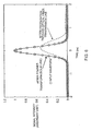
- Fig. 5 shows a waveform distortion of an optical pulse and the effects of compensation.
- the graph shows the results of numerical calculations performed to confirm the effects of dispersion compensation by the optical Fourier transmission method of the present embodiment, by using the experimental parameters indicated in the non-patent document 4.
- a series of circles, a broken line, and a solid line represent time-domain waveforms of an optical signal respectively at point A (before transmission through the optical fiber transmission line 2), point B (after transmission), and point C (output of the optical Fourier transform circuit 3) shown in Fig. 1 .
- the time-domain waveform at point A in Fig. 1 is assumed to be of a Gaussian pulse with 380-fs full width at half maximum, for instance. It is assumed that the accumulated dispersion of fibers having a length ⁇ of 69.4 km included in the optical fiber transmission line is:
- the fourth-order dispersion is dominant.
- the waveform Prior to dispersion compensation by the optical Fourier transform circuit, the waveform is greatly distorted by the fourth-order dispersion in such a manner that the pulse is broadened symmetrically with respect to time.
- the graph shows that the time-domain waveform input to the transmission line is reproduced precisely after the Fourier transform of this method.
- Fig. 6 shows other results of numerical calculations related to a waveform distortion of an optical pulse and the effects of compensation.
- This graph shows the results of numerical calculations conducted to confirm the effects of the present embodiment.
- a series of circles, a broken line, and a solid line represent time-domain waveforms of an optical signal respectively at points A, B, and C shown in Fig. 1 . It is assumed that the time-domain waveform at point A in Fig. 1 is of a Gaussian pulse with a 380-fs full width at half maximum, and that the accumulated dispersion of 69.4-km fibers in the optical fiber transmission line is:
- the time-domain waveform of an optical pulse train affected by linear distortions in an optical fiber transmission line can be converted to an invariant frequency spectrum, the spectrum of the signal input to the transmission line can be reproduced, and the information can be directly taken out, by using an optical Fourier transform circuit including a phase modulator and a second-order dispersion element. Accordingly, the optical Fourier transmission method according to the present invention enables information to be transmitted correctly, independently of the propagation characteristics of the optical fiber transmission line.
- waveform distortions of the time-domain waveform of an optical pulse caused by the linear effects of an optical fiber transmission line having third-order or higher-order dispersion and arbitrary dispersion or polarization-mode dispersion with time variation can be compensated for simultaneously and completely, and the transmission capacity and the transmission distance of optical fiber communication can be increased. Because precise control of dispersion and polarization-mode dispersion of the optical fiber transmission line is not necessary, practical and economical optical fiber communication can be implemented.
Description
- The present invention relates to optical transmission methods, and more specifically, to an optical transmission method for simultaneously and completely compensating for waveform distortions in a signal transmitted through an optical fiber including third-order or higher-order dispersion and arbitrary dispersion or polarization-mode dispersion with time variation by means of a Fourier transform.
- It is widely known that linear effects such as wavelength dispersion and polarization dispersion in an optical fiber lead to distortions in a time-domain waveform such as broadening of a pulse, ripples, and a shift in position of center time. Especially in ultrahigh-speed time-division multiplexed transmission at a speed higher than or equal to 40 Gb/s per channel, waveform distortions resulting from third-order or higher-order dispersion and polarization-mode dispersion have a great effect.
- Compensation for second-order dispersion by a dispersion compensating fiber or a grating, simultaneous compensation for second-order and third-order dispersion by a reverse-dispersion slope fiber, compensation for dispersion through the use of a phase-conjugate element, and others have been put forth to compensate for the effects of linear distortions in an optical fiber transmission line, and a dispersion-flattened fiber transmission line has been equivalently implemented.
- Conventional technologies reported by Pelusi et al. compensate for third-order and fourth-order dispersion by applying a linear chirp to a signal by means of a fiber having an appropriate amount of second-order dispersion before transmission and then performing sinusoidal phase modulation or cosine phase modulation depending on the magnitude of third-order or fourth-order dispersion of the transmission fiber (see
patent document 1, non-patentdocuments 1 and 2). It has been reported that other conventional technologies can compensate for third-order and fourth-order dispersion of a transmission line simultaneously by selecting appropriate amplitude and timing of cosine phase modulation (see non-patent documents 3 and 4). With these technologies, 1.28 Tb/s - 70 km optical time-division multiplexed transmission can be successfully performed. Use of an optical Fourier transform has been suggested to compensate for group delay resulting from polarization-mode dispersion (patent document 2, non-patent document 5).
patent document 1
JP 2001-111490 A
patent document 2
NP 2002-541720 A
Non-patentdocument 1
M. D. Pelusi, Y. Matsui, and A. Suzuki, "Phase modulation of stretched optical pulses for suppression of third-order dispersion effects in fiber transmission," Electron. Lett. Vol. 34, pp. 1675-1677 (1998)
Non-patentdocument 2
M. D. Pelusi, Y. Matsui, and A. Suzuki, "Fourth-order dispersion suppression of ultrashort optical pulses by second-order dispersion and cosine phase modulation," Opt. Lett. Vol. 25, pp. 296-298 (2000)
Non-patent document 3
T. Yamamoto and M. Nakazawa, "Third- and fourth-order active dispersion compensation with a phase modulator in a terabit-per-second optical time-division multiplexed transmission," Opt. Lett. Vol. 26, pp. 647-649 (2001)
Non-patentdocument 4
M. Nakazawa, T. Yamamoto, and K. R. Tamura, "1.28 Tbit/s - 70 km OTDM transmission using third- and fourth-order simultaneous dispersion compensation with a phase modulator," ECOC 2000, PD. 2.6
Non-patentdocument 5
M. Romagnoli, P. Franco, R. Corsini, A. Schffini, and M. Midrio, "Time-domain Fourier optics for polarization-mode dispersion compensation," Opt. Lett. Vol. 24, pp. 1197-1199 (1999)
EP0817409 A2 discloses a method and device for the generation of transform-limited ultra-short optical pulses. - It is generally recognized that dispersion compensation by a fiber is easy while simultaneous compensation for wavelength dispersion including third-order dispersion is difficult, because the technique requires matching of a ratio of second-order dispersion to third-order dispersion. If a phase-conjugate element is used, only even-numbered-order dispersion can be compensated for. If pre-transmission dispersion compensation by phase modulation is performed, a precise dispersion value of the whole transmission line must be obtained before phase modulation is adjusted.
- The conventional techniques use a constant amount of dispersion compensation and cannot vary the amount of dispersion compensation dynamically with the dispersion value varying with time. Accordingly, an adaptive equalization scheme has been required. The conventional techniques cannot compensate for polarization-mode dispersion.
- Unlike the conventional techniques for compensating for waveform distortions completely in the time domain, a technique according to the present invention compensates for waveform distortions by taking advantage of characteristics in which the spectral profile remains unchanged even if any type of linear distortion occurs in the time domain, to solve these issues all at once. In other words, an objective of the present invention is to reproduce an original signal waveform with few linear distortions or without linear distortions, by Fourier-transforming the spectral profile of a transmitted optical signal to one bit in the time domain, and to implement substantially distortion-free optical fiber transmission.
- The present invention provides an optical transmission method for performing digital modulation of an optical pulse as a transmission signal at a transmission end, propagating the pulse through an optical fiber transmission line, and converting the pulse to an electric signal by a photoreceiver, wherein an optical Fourier transformer is disposed before the photoreceiver, the optical Fourier transformer switching between the time-domain waveform of the optical pulse and a frequency spectrum thereof on a time-axis, characterized by: using a pulse which has a time-domain waveform equal to an envelope profile of a frequency spectrum in a function form, and is transform-limited in which a product of the full width at half maximum and the frequency spectral width satisfies the Fourier limit condition, as the optical pulse transmitted; taking advantage of the characteristic in which the envelope profile of the frequency spectrum is distortion-free before and after transmission in a linear transmission even if the time-domain waveform is distorted; and the optical Fourier transformer performing Fourier transformation to the time-domain waveform of the signal pulse transmitted through the optical fiber transmission line and distorted, such that the time-domain waveform becomes a waveform expressed by the envelope profile of the frequency spectrum which is distortion free..
- The present invention enables simultaneous and complete compensation or nearly complete compensation for linear distortions of a time-domain waveform caused by third-order or higher-order dispersion and arbitrary dispersion or polarization-mode dispersion with time variation, which used to be hard to compensate, so that the transmission capacity and transmission distance of optical fiber communication can be increased.
- The present invention also enables practical and economical optical fiber communication to be implemented, eliminating the need for compensating for dispersion of an optical fiber or polarization-mode dispersion precisely.
-
-
Fig. 1 shows an optical Fourier transmission system according to an embodiment of the present invention. -
Fig. 2 shows a time-domain waveform of an optical pulse. -
Fig. 3 shows the profile of the frequency spectrum of the optical pulse. -
Fig. 4 shows the configuration of an optical Fourier transform circuit 3. -
Fig. 5 shows a waveform distortion of an optical pulse and the effects of compensation. -
Fig. 6 shows other results of numerical calculations related to a waveform distortion of an optical pulse and the effects of compensation. - An embodiment of the present invention is described below in detail with reference to the drawings.
-
Fig. 1 shows an embodiment of an optical Fourier transmission system according to the present invention. The optical Fourier transmission system includes anoptical pulse transmitter 1, an opticalfiber transmission line 2, an optical Fourier transform circuit 3, and aphotoreceiver 4. As an optical receiver, an optical transmission apparatus includes the optical Fourier transform circuit 3 and thephotoreceiver 4. - The
optical pulse transmitter 1 converts an electric signal carrying information to be transmitted into an optical signal, through digital modulation of an optical pulse generated from a light source by an electric signal, and emits a train of optical pulses carrying the information into the opticalfiber transmission line 2. It is preferable that the product of the pulse width and the spectral width satisfy the condition of being at the Fourier limit (ΔνΔτ ≅ 0.441 for a Gaussian pulse and ΔνΔτ ≅ 0.315 for a sech pulse, where Δν indicates spectral width and Δτ indicates time-domain pulse width). An optical pulse having the best spectral width with respect to the time-domain waveform is called a Fourier-limited pulse (hereafter referred to as a transform-limited pulse). With the transform-limited optical pulse, ideal optical Fourier transmission can be implemented with the best performance. - The optical
fiber transmission line 2 is a transmission line including various kinds of optical fibers having arbitrary dispersion and polarization-mode dispersion. The amounts of these types of dispersion may vary with time. - The optical Fourier transform circuit 3 receives an optical pulse transmitted through the optical
fiber transmission line 2 and Fourier-transforms the pulse train in the time domain to a spectrum in the frequency domain. In high-speed time-division multiplexing, the optical Fourier transform circuit 3 may perform Fourier transform after the signal is demultiplexed to low-rate signals. - The
photoreceiver 4 receives an optical pulse in which dispersion and polarization-mode dispersion caused by the opticalfiber transmission line 2 has been compensated for by the optical Fourier transform circuit 3 and converts the pulse into an electric signal. Thephotoreceiver 4 is a PIN, an APD, and any other appropriate photodetector. - An overview of the operation of the optical Fourier transmission system is given below. An optical signal transmitted through the optical
fiber transmission line 2 is generally an optical time-division multiplexed signal. In the operation of the present embodiment, an optical pulse train making up a time-division multiplexed signal is input to the optical Fourier transform circuit 3. Each pulse of the optical pulse train will be described below. -
Fig. 2 shows time-domain waveforms of an optical pulse.Figs. 2(a), 2(b), and 2(c) show overviews of the time-domain waveforms of the optical pulse respectively at points A, B, and C of the optical fiber transmission line shown inFig. 1 . -
Fig. 3 shows the profiles of the frequency spectra of the optical pulse.Figs. 3(a), 3(b), and 3(c) show overviews of the frequency spectra of the optical pulse respectively at points A, B, and C of the optical fiber transmission line shown inFig. 1 . - The
optical pulse transmitter 1 converts an electric signal to an optical pulse, and the optical pulse enters and travels through the opticalfiber transmission line 2. It is preferable that theoptical pulse transmitter 1 shapes the frequency spectrum Uin(ω) of the optical pulse (Fig. 3(a) ), so that the optical pulse has the time-domain waveform uin(t) (Fig. 2(a) ) of a Fourier-limited pulse (transform-limited pulse) when the pulse enters the opticalfiber transmission line 2. - The optical pulse traveling through the optical
fiber transmission line 2 usually undergoes complicated linear distortions resulting from dispersion and polarization-mode dispersion of the opticalfiber transmission line 2. These distortions determine the transmission performance of the conventional optical communication. The present embodiment, however, allows, as a main feature, the original waveform to be reproduced completely in the frequency domain because the envelope profile of the spectrum input to the opticalfiber transmission line 2 is not deformed at all by dispersion and polarization-mode dispersion of the opticalfiber transmission line 2. The effect of dispersion in an optical fiber is converted to a phase shift in each frequency component of the spectrum, but the photodetector detects just the envelope. Accordingly, the phase shift presents no problem. A key is that the optical Fourier transform circuit reproduces a frequency spectrum U(ω) (Fig. 3(b) ) in the time domain, from a time signal u(t) (Fig. 2(b) ) affected by linear distortions in the opticalfiber transmission line 2. - In other words, the time-domain waveform of a transmitted optical pulse goes through the optical Fourier transform circuit 3, and the frequency spectrum of the optical pulse is reproduced in the time domain by replacing time with frequency. This allows the frequency spectrum (
Fig. 3(a) ) of the optical pulse input to the opticalfiber transmission line 2 at point A shown inFig. 1 to be completely reproduced at an output end (Fig. 2(c) ). The optical pulse passing through the optical Fourier transform circuit 3 is converted back to an electric signal by thephotoreceiver 4 and is taken out as a signal. This optical transmission method is named as "optical Fourier transmission." -
Fig. 4 shows the configuration of the optical Fourier transform circuit 3. The optical Fourier transform circuit 3 includes anoptical coupler 5, aclock extraction circuit 6, aphase shifter 7, anelectric amplifier 8, adelay fiber 9, aphase modulator 10, and a second-order dispersion element 11. - As the
phase modulator 10, a phase modulator using the electrooptic effect of LiNbO3 and others is recommended, for instance. Thephase modulator 10 may also use the phase modulation effect of electroabsorption (EA) or a semiconductor optical amplifier (SOA). Althoughmany phase modulators 10 have polarization dependence, it is preferable that polarization is eliminated by using a polarization-free optical device or a polarization diversity method. The driving frequency of thephase modulator 10 is the pulse transmission rate. - The
optical coupler 5 separates a portion of the transmission signal into two parts, one part to thedelay fiber 9 and the other part to theclock extraction circuit 6, so that thephase modulator 10 performs phase modulation in synchronization with the pulse transmitted through the opticalfiber transmission line 2. Theclock extraction circuit 6 extracts a clock signal (a sinusoidal signal) from the transmission signal and drives thephase modulator 10 at the obtained clock frequency through thephase shifter 7 and theelectric amplifier 8. Thephase shifter 7 and thedelay fiber 9 function to ensure that optimal phase modulation takes place in synchronization with the optical pulse. If the timing of modulation changes because of a change in temperature, thephase shifter 7 can automatically adjust the amount of the phase shift so that optimum modulation can be performed. Theelectric amplifier 8 outputs a drive signal for driving thephase modulator 10, depending on the output of thephase shifter 7. - The second-
order dispersion element 11 can be a single-mode optical fiber having group velocity dispersion with zero-dispersion region near the 1.3-µm band, a pair of diffraction gratings, a fiber Bragg grating, a VIPA variable dispersion compensator, an arrayed waveguide grating, a combination of a diffraction grating and a spatial modulator, and others, for instance. - A stand-alone optical Fourier transform circuit has been originally designed to compensate for group delay caused by polarization-mode dispersion, as described in a paper and others on optical Fourier transform, written by Romagnoli et al. (
patent document 2, non-patent document 5). In the previous technique discussed in that paper and others, the optical Fourier transform circuit is used to compensate for polarization-mode dispersion alone. The concept has not reached an idea of performing distortion-free transmission by replacing time with frequency as implemented by the optical Fourier transform circuit 3 of the present embodiment. The present invention offers a new principle and technique of optical Fourier transmission that eliminates all linear distortions by converting distortions in the time domain into the spectrum. - Described below in further detail is how the optical Fourier transmission method is used to compensate for waveform distortions of an optical pulse caused by the linear effects of an optical fiber transmission line having arbitrary dispersion and polarization-mode dispersion, in the configuration of the present embodiment.
- If the pulse envelope varies more slowly than the carrier frequency, pulse propagation in the optical fiber is described by envelope approximation. The slowly-varying field envelope amplitude of the pulse is represented as u(z, t); the propagation constant in the medium is represented as β(ω); the frequency of the carrier wave will be represented as ω0; where t is time, z is the position (coordinates) in the longitudinal direction of the optical fiber, and ω is frequency. The electric field e(z, t) in the optical fiber is expressed as:

where β is given by:
In the equation, β0, β1...., βn are given below:
The optical electric field e(z, t) in a dispersive medium such as an optical fiber satisfies the Maxwell's equation:
Therefore, the frequency spectrum E(z, ω) of the optical electric field e(z, t) satisfies the following equation (the frequency spectrum may be referred to simply as the spectrum):
where E(z, ω) is given by:
The spectral width of the pulse is not so large in comparison with the carrier frequency, so that ω2 is approximated as ω0 2 in theequation 4. - An equation about the envelope u(z, t) is important. A Fourier transform U(z, ω - ω0) of u(z, t) will be considered. With the
equations 
where U(z, ω - ω0) is given by:
- If the
equation 6 is substituted into theequation 4, if the second differential of z is ignored because U(z, ω - ω0) changes gradually with respect to z, and if
is used, the following propagation equation satisfied by U(z, ω - ω0) is obtained:
Based on theequation 2, the basic equation in the time domain can be expressed as:
- An inverse Fourier transform of the
equation 9 yields the following linear wave equation satisfied by u(z, t) finally:
where u(z, t) is given by:
In the subsequent part, (ω - ω0) will be defined as ω. Now, distortions of the time-domain waveform of a pulse caused by the linear effects of a transmission line are completely expressed by theequation 10. - In the frequency domain, however, the optical signal generally undergoes just a phase change under any linear effects, and the spectral profile is completely maintained (see equation 12 below). The time-domain waveform of an optical pulse input to an optical
fiber transmission line 2 having a length z = ξ from theoptical pulse transmitter 1 will be represented as uin(t) (= u(0, t)), and the frequency spectrum of the pulse will be represented as Uin(ω) (= U(0, ω)). The time-domain waveform of a signal affected by linear distortions in the opticalfiber transmission line 2 will be represented as u(t) (= u(z, t)), and the frequency spectrum of the signal will be represented as U(ω) (= U(z, ω)). The integration of theequation 8 yields the following spectrum after propagation through the fiber having a length of ξ:
The equation indicates that the spectral profile is maintained, except for the phase change exp[iβ(ω)ξ]. - The optical Fourier transform circuit 3 obtains the frequency spectrum U(ξ,ω) from the time-domain waveform u(ξ, t) at the receiver side B of the optical
fiber transmission line 2 having a length of ξ, in the method described below. In the subsequent part, u(ξ, t) will be expressed as u(t), and U(ξ,ω) will be expressed as U(ω). - A time-domain signal after a parabolic phase modulation exp(iKt2/2) of the transmitted pulse signal u(t) by the
phase modulator 10 is given by multiplying u(t) by the amount of phase change:
The input waveform of thephase modulator 10 is u(t), and the output waveform is u'(t) obtained by theequation 13. The processing of thephase modulator 10 corresponds to the multiplication of the input waveform u(t) by the phase exp(iKt2/2) on the right side of theequation 13. The chirp rate K is given to thephase modulator 10 in advance as a parameter. This parameter can be controlled, depending on the magnitude of the voltage applied to the phase modulator. The timing of phase modulation and the driving frequency are extracted from and adjusted to the transmission signal, by using theclock extraction circuit 6, thephase shifter 7, and thedelay fiber 9. - If v(t) is a signal after propagation through dispersion k"L by the second-
order dispersion element 11, v(t) is given as follows, as a time-domain waveform of u'(t) after propagation through the second-order dispersion (element) expressed as D = k"L:
The input waveform of the second-order dispersion element 11 is u' (t) obtained by theequation 13, and the output waveform is v(t) obtained by the equation 14. The output waveform v(t) is obtained by applying the second-order dispersion function exp(iDω2/2) to the Fourier-transformed u'(t) in the frequency domain and by inverse-transforming the whole. The second-order dispersion function is obtained by substituting Dω2/2 for β(ω) in the equation 12. - Next, the phase modulation parameter K of the phase modulator is selected to satisfy K = 1/D. By substituting T for (t' - t), the equation 14 can be rewritten as follows:

The equation 15 indicates that the output time-domain waveform v(t) (Fig. 2(c) ) of the optical Fourier transform circuit 3 is proportional to the spectrum U(ω) (Fig. 3(b) ) of the input waveform to the optical Fourier transform circuit 3. Here,
In other words, the output time-domain waveform v(t) of the optical Fourier transform circuit 3 corresponds to the spectral profile U(ω) of the input waveform of the optical Fourier transform circuit 3 when the scale of the time is converted to t/D = ω. - Because the linear transmission maintains the spectrum, as expressed by the equation 12, the envelope profile of the spectrum U(ω) at the receiver side B (
Fig. 3(b) ) agrees with the envelope profile of the spectrum U(0, ω) (= (Uin(ω)) of the signal at the transmitter side A. With equations 12 and 15, v(t) is expressed with the spectrum Uin of the signal input to the opticalfiber transmission line 2, as follows:
With v(t), the profile of the input spectrum Uin(ω) can be reproduced at the output. It has already been known that a combination of thephase modulator 10 and the second-order dispersion element 11 can generate a Fourier-transformed image of an optical pulse, but the present invention has such a distinctive feature that waveform-distortion-free transmission can be implemented by an apparatus for optical Fourier transform. - If the signal has the waveform of a transform-limited pulse, the time-domain waveform can be directly obtained from the frequency spectrum. Suppose that the time-domain waveform of a signal input to the optical
fiber transmission line 2 has a Gaussian waveform uin(t) = Aexp (-t2/2T0 2) of a transform-limited pulse. A Fourier transform does not change the function form of the waveform of the Gaussian pulse, as well as that of a sech pulse. The spectrum is given by:
The output waveform of the optical Fourier transform circuit 3 is given by substituting t/D for ω in the equation 17:
If the absolute value of the second-order dispersion is selected as |D| = T0 2, the equation 19 is rewritten as:
A typical photodetector contained in thephotoreceiver 4 detects a optical electric field intensity I(t) = |v(t)|2. Therefore, the time-domain waveform uin(t) = Aexp(-t2/2T0 2) at the transmitter side A (Fig. 2(a) ) can be directly reproduced from v(t) of the equation 20:
For a Gaussian waveform, if |D| = T0 2 is selected, the spectrum Uin(t/D) directly corresponds to the time-domain waveform uin(t) in theequation 17. Accordingly, the time-domain waveform before affected by the linear effects of the optical fiber transmission line can be reproduced at the output end C in the time domain directly with preciseness or completely. - If the waveform is not Gaussian, the intensity I(t) |v(t)|2 of the optical electric field is obtained from the output of the
photoreceiver 4 as follows:
- What is important in this method is that any linear transmission distortion is compensated for, independently of the type and the magnitude. Accordingly, the magnitude of the dispersion value, the dynamic variation with time, and the order of dispersion are irrelevant. This method can be equally applied to soliton and other non-linear pulse transmission if the spectral shape is maintained after propagation. Because a soliton transmission pulse has a transform-limited relationship between the time width Δτ and the spectrum width Δν, this method is applicable. Dispersion-managed (DM) soliton transmission can also use this method at a position of the shortest pulse where a chirp is zero or by inserting an appropriate fiber to bring the chirp to zero.
-
Fig. 5 shows a waveform distortion of an optical pulse and the effects of compensation. The graph shows the results of numerical calculations performed to confirm the effects of dispersion compensation by the optical Fourier transmission method of the present embodiment, by using the experimental parameters indicated in thenon-patent document 4. In the figure, a series of circles, a broken line, and a solid line represent time-domain waveforms of an optical signal respectively at point A (before transmission through the optical fiber transmission line 2), point B (after transmission), and point C (output of the optical Fourier transform circuit 3) shown inFig. 1 . - The time-domain waveform at point A in
Fig. 1 is assumed to be of a Gaussian pulse with 380-fs full width at half maximum, for instance. It is assumed that the accumulated dispersion of fibers having a length ξ of 69.4 km included in the optical fiber transmission line is: - β2ξ = -0.0037 ps2
- β3ξ = -0.0038 ps3
- β4ξ = 0.0058 ps4
and - To = 228 fs
- Because the value of β4 is large in the transmission line, the fourth-order dispersion is dominant. Prior to dispersion compensation by the optical Fourier transform circuit, the waveform is greatly distorted by the fourth-order dispersion in such a manner that the pulse is broadened symmetrically with respect to time. The graph shows that the time-domain waveform input to the transmission line is reproduced precisely after the Fourier transform of this method.
-
Fig. 6 shows other results of numerical calculations related to a waveform distortion of an optical pulse and the effects of compensation. This graph shows the results of numerical calculations conducted to confirm the effects of the present embodiment. In the figure, a series of circles, a broken line, and a solid line represent time-domain waveforms of an optical signal respectively at points A, B, and C shown inFig. 1 . It is assumed that the time-domain waveform at point A inFig. 1 is of a Gaussian pulse with a 380-fs full width at half maximum, and that the accumulated dispersion of 69.4-km fibers in the optical fiber transmission line is: - β2ξ = -0.0037 ps2
- β2ξ = 0.1 ps3
- β2ξ = -0.0058 ps4
- As described above in detail, according to the present invention, the time-domain waveform of an optical pulse train affected by linear distortions in an optical fiber transmission line can be converted to an invariant frequency spectrum, the spectrum of the signal input to the transmission line can be reproduced, and the information can be directly taken out, by using an optical Fourier transform circuit including a phase modulator and a second-order dispersion element. Accordingly, the optical Fourier transmission method according to the present invention enables information to be transmitted correctly, independently of the propagation characteristics of the optical fiber transmission line.
- According to the present invention, waveform distortions of the time-domain waveform of an optical pulse, caused by the linear effects of an optical fiber transmission line having third-order or higher-order dispersion and arbitrary dispersion or polarization-mode dispersion with time variation can be compensated for simultaneously and completely, and the transmission capacity and the transmission distance of optical fiber communication can be increased. Because precise control of dispersion and polarization-mode dispersion of the optical fiber transmission line is not necessary, practical and economical optical fiber communication can be implemented.
If a single-mode optical fiber with zero dispersion at 1.3 µm (k" = -20 ps2/km) is used as a second-order dispersion element of the optical Fourier transform circuit, a length of 2.6 m is required. This method also allows the waveform to be easily reproduced by using a single phase modulator and a short fiber. The chirp rate of the phase modulator is:
Claims (3)
- An optical transmission method for performing digital modulation of an optical pulse as a transmission signal at a transmission end (1), propagating the pulse through an optical fiber transmission line (2), and converting the pulse to an electric signal by a photoreceiver (4),
wherein an optical Fourier transformer (3) is disposed before the photoreceiver (4), the optical Fourier transformer (3) switching between the time-domain waveform of the optical pulse and a frequency spectrum thereof on a time-axis,
characterized by:using a pulse which has a time-domain waveform equal to an envelope profile of a frequency spectrum in a function form, and is transform-limited in which a product of the full width at half maximum and the frequency spectral width satisfies the Fourier limit condition, as the optical pulse transmitted,taking advantage of the characteristic in which the envelope profile of the frequency spectrum is distortion-free before and after transmission in a linear transmission even if the time-domain waveform is distorted, andthe optical Fourier transformer performing Fourier transformation to the time-domain waveform of the signal pulse transmitted through the optical fiber transmission line and distorted, such that the time-domain waveform becomes a waveform expressed by the envelope profile of the frequency spectrum which is distortion free. - An optical transmission method according to Claim 1, wherein third-order or higher-order dispersion causing pulse distortions in the optical fiber (2) are completely compensated.
- An optical transmission method according to Claim 1, wherein distortion-free optical transmission can always be implemented, independently of variation in arbitrary dispersion or polarization-mode dispersion with time.
Applications Claiming Priority (3)
| Application Number | Priority Date | Filing Date | Title |
|---|---|---|---|
| JP2003023973 | 2003-01-31 | ||
| JP2003023973A JP4471572B2 (en) | 2003-01-31 | 2003-01-31 | Optical transmission method |
| PCT/JP2004/000589 WO2004068747A1 (en) | 2003-01-31 | 2004-01-23 | Optical transmission method and optical transmission device |
Publications (3)
| Publication Number | Publication Date |
|---|---|
| EP1589679A1 EP1589679A1 (en) | 2005-10-26 |
| EP1589679A4 EP1589679A4 (en) | 2008-01-23 |
| EP1589679B1 true EP1589679B1 (en) | 2012-11-14 |
Family
ID=32820748
Family Applications (1)
| Application Number | Title | Priority Date | Filing Date |
|---|---|---|---|
| EP04704719A Expired - Fee Related EP1589679B1 (en) | 2003-01-31 | 2004-01-23 | Optical transmission method and optical transmission device |
Country Status (6)
| Country | Link |
|---|---|
| US (1) | US7747175B2 (en) |
| EP (1) | EP1589679B1 (en) |
| JP (1) | JP4471572B2 (en) |
| KR (1) | KR100759785B1 (en) |
| CN (1) | CN1736048B (en) |
| WO (1) | WO2004068747A1 (en) |
Families Citing this family (12)
| Publication number | Priority date | Publication date | Assignee | Title |
|---|---|---|---|---|
| JP4495415B2 (en) | 2003-06-26 | 2010-07-07 | 独立行政法人科学技術振興機構 | OTDM transmission method and apparatus |
| KR100703410B1 (en) | 2005-01-19 | 2007-04-03 | 삼성전자주식회사 | Offset quadrature phase-shift-keying method and optical transmitter using the same |
| ES2259267B1 (en) * | 2005-03-05 | 2007-10-01 | Universidad Politecnica De Valencia | METHOD AND MEASUREMENT DEVICE OF THE POLARIZATION STATE AND THE MODAL DISPERSION BY POLARIZATION IN PHOTONIC TRANSMISSION SYSTEMS. |
| US7813035B2 (en) * | 2006-05-18 | 2010-10-12 | Polaronyx, Inc. | Nonlinearity and dispersion management for pulse reshaping in high energy fiber amplifier |
| US7873272B2 (en) * | 2006-11-13 | 2011-01-18 | Alcatel-Lucent Usa Inc. | Optical pulse characterization using phase modulation |
| JP5455053B2 (en) * | 2010-02-24 | 2014-03-26 | 国立大学法人東北大学 | Apparatus and method for removing waveform distortion of ultrafast optical pulse |
| US8452179B2 (en) * | 2010-02-26 | 2013-05-28 | Cisco Technology, Inc. | Remotely settable chromatic dispersion robustness for dense wave division multiplexing interfaces |
| US9003101B1 (en) | 2011-06-29 | 2015-04-07 | Western Digital Technologies, Inc. | Prioritized access for media with heterogeneous access rates |
| CN102664685B (en) * | 2012-04-12 | 2015-05-27 | 武汉邮电科学研究院 | Device and method for restraining in-band white noise in high-speed optical fiber communication system |
| CN102710287B (en) * | 2012-06-06 | 2014-08-13 | 西南交通大学 | Tunable ultra-wideband microwave signal generator based on microwave photonic technology |
| CN108169133B (en) * | 2017-12-28 | 2020-03-24 | 清华大学 | Line scanning sparse sampling two-photon imaging method and device |
| CN111947793B (en) * | 2020-07-17 | 2022-11-22 | 西安工程大学 | Time domain-frequency domain converter for ultrafast process detection |
Family Cites Families (18)
| Publication number | Priority date | Publication date | Assignee | Title |
|---|---|---|---|---|
| FR2540870A1 (en) * | 1983-02-15 | 1984-08-17 | Provesan Sa | NOVEL DERIVATIVES OF N-IMINOPYRIDINIUM BETA, THEIR PREPARATION AND THEIR APPLICATION AS MEDICAMENTS |
| IT1286140B1 (en) | 1996-07-02 | 1998-07-07 | Cselt Centro Studi Lab Telecom | PROCEDURE AND DEVICE FOR THE GENERATION OF ULTRA SHORT OPTICAL IMPULSES. |
| DE19638879A1 (en) * | 1996-09-23 | 1998-03-26 | Thomson Brandt Gmbh | Method for processing the output signals of an optoelectronic scanner in a reproduction or recording device and corresponding device |
| JP3289657B2 (en) | 1997-10-03 | 2002-06-10 | 日本電信電話株式会社 | Optical communication device |
| JP3443534B2 (en) * | 1998-12-17 | 2003-09-02 | 日本電信電話株式会社 | Atomic frequency standard laser pulse oscillator |
| EP1171968B1 (en) | 1999-04-01 | 2002-11-20 | Optical Technologies U.S.A. Corp. | Device and method for compensating polarization mode dispersion in an optical communication system |
| US20010053008A1 (en) * | 1999-09-01 | 2001-12-20 | Yoshiyasu Ueno | Optical pulse generating apparatus and optical signal apparatus using the same |
| JP3542935B2 (en) | 1999-10-13 | 2004-07-14 | 日本電気株式会社 | Optical fiber dispersion compensation method |
| US6879640B1 (en) * | 1999-10-20 | 2005-04-12 | Broadcom Corporation | Method, apparatus and system for high-speed transmission on fiber optic channel |
| US7224906B2 (en) * | 2000-09-26 | 2007-05-29 | Celight, Inc. | Method and system for mitigating nonlinear transmission impairments in fiber-optic communications systems |
| US7181097B2 (en) * | 2001-03-15 | 2007-02-20 | Massachusetts Institute Of Technology | Methods of achieving optimal communications performance |
| JP2002300116A (en) * | 2001-03-30 | 2002-10-11 | Oki Electric Ind Co Ltd | Optical communication device |
| US7142486B2 (en) * | 2001-04-02 | 2006-11-28 | Ricoh Company, Ltd. | Signal processing method and signal processing apparatus |
| US7509048B2 (en) * | 2001-07-20 | 2009-03-24 | Essex Corporation | Method and apparatus for optical signal processing using an optical tapped delay line |
| US7013063B2 (en) | 2001-12-31 | 2006-03-14 | 3M Innovative Properties Company | System for higher-order dispersion compensation including phase modulation |
| US6963685B2 (en) * | 2002-07-09 | 2005-11-08 | Daniel Mahgerefteh | Power source for a dispersion compensation fiber optic system |
| KR100528966B1 (en) * | 2002-12-10 | 2005-11-15 | 한국전자통신연구원 | PMD compensator based on separation of principal state of polarization control and differential group delay control, and method thereof |
| JP4471666B2 (en) * | 2004-01-05 | 2010-06-02 | 独立行政法人科学技術振興機構 | Optical Fourier transform apparatus and method |
-
2003
- 2003-01-31 JP JP2003023973A patent/JP4471572B2/en not_active Expired - Fee Related
-
2004
- 2004-01-23 WO PCT/JP2004/000589 patent/WO2004068747A1/en active Search and Examination
- 2004-01-23 KR KR1020057013435A patent/KR100759785B1/en not_active IP Right Cessation
- 2004-01-23 CN CN2004800019750A patent/CN1736048B/en not_active Expired - Fee Related
- 2004-01-23 US US10/543,342 patent/US7747175B2/en not_active Expired - Fee Related
- 2004-01-23 EP EP04704719A patent/EP1589679B1/en not_active Expired - Fee Related
Also Published As
| Publication number | Publication date |
|---|---|
| JP4471572B2 (en) | 2010-06-02 |
| WO2004068747A1 (en) | 2004-08-12 |
| CN1736048B (en) | 2012-08-22 |
| CN1736048A (en) | 2006-02-15 |
| KR100759785B1 (en) | 2007-09-20 |
| JP2004266339A (en) | 2004-09-24 |
| EP1589679A4 (en) | 2008-01-23 |
| EP1589679A1 (en) | 2005-10-26 |
| KR20050096145A (en) | 2005-10-05 |
| US20060232847A1 (en) | 2006-10-19 |
| US7747175B2 (en) | 2010-06-29 |
Similar Documents
| Publication | Publication Date | Title |
|---|---|---|
| EP0703680B1 (en) | Apparatus and method for compensating chromatic dispersion produced in optical phase conjugation or other types of optical signal conversion | |
| EP0901244B1 (en) | Transmission system with cross-phase and/or self-phase modulation compensation | |
| US5877881A (en) | Optical transmission system | |
| EP0898391B1 (en) | Minimizing dispersion in optical-fiber transmission lines | |
| EP1323250B1 (en) | Method and system for transmitting signals with spectrally enriched optical pulses | |
| EP1589679B1 (en) | Optical transmission method and optical transmission device | |
| JPH05265060A (en) | Superlong distance digital transmission equipment using optical fiber for compensating distortion of receiving terminal | |
| EP1705516B1 (en) | Optical fourier transform device and method | |
| EP0902560A2 (en) | Method and apparatus for optimizing dispersion in an optical fiber transmission line in accordance with an optical signal power level | |
| US7672593B2 (en) | OTDM transmission method and apparatus | |
| EP1404038A1 (en) | Method for reduction of non-linear distortions in an optical transmission channel | |
| Mollenauer et al. | Time-lens timing-jitter compensator in ultra-long haul DWDM dispersion managed soliton transmissions | |
| US20020057478A1 (en) | System and transmitter for transmitting optical data | |
| Bononi et al. | Impulse response of cross-phase modulation filters in multi-span transmission systems with dispersion compensation | |
| Lee | Decaying/expanding distribution of RDPS in the half section of a dispersion-managed optical link combined with mid-span spectral inversion | |
| Agrawal | Optical communication systems (OPT428) | |
| JP3660597B2 (en) | High-order dispersion simultaneous compensation method and apparatus | |
| Biswas | Higher-order Gabitov–Turitsyn equation for solitons in optical fibers | |
| Røyset et al. | Transmission of< 10ps pulses over 318km standard fiber using midspan spectral inversion | |
| Biswas | Asymptotic analysis for dispersion-managed solitons in multiple channels | |
| Binh et al. | Technical Report MECSE-6-2005 | |
| Sabapathi et al. | Impact of Cross Phase Modulation in Long Haul DWDM Fiber Optic Communication and its Suppression | |
| Killey et al. | Long-Haul and Access Networks, 67 Optical Metro and WDM A. Lord et al.(Eds.) IOS Press, 2001© AKM | |
| Hasegawa et al. | Application of Dispersion Managed Solitons for WDM Transmission | |
| Badraoui | PROPAGATION PROBLEMS OF SOLITONS IN FIBERS |
Legal Events
| Date | Code | Title | Description |
|---|---|---|---|
| PUAI | Public reference made under article 153(3) epc to a published international application that has entered the european phase |
Free format text: ORIGINAL CODE: 0009012 |
|
| 17P | Request for examination filed |
Effective date: 20050805 |
|
| AK | Designated contracting states |
Kind code of ref document: A1 Designated state(s): AT BE BG CH CY CZ DE DK EE ES FI FR GB GR HU IE IT LI LU MC NL PT RO SE SI SK TR |
|
| AX | Request for extension of the european patent |
Extension state: AL LT LV MK |
|
| DAX | Request for extension of the european patent (deleted) | ||
| RBV | Designated contracting states (corrected) |
Designated state(s): DE FR GB IT NL SE |
|
| A4 | Supplementary search report drawn up and despatched |
Effective date: 20071227 |
|
| 17Q | First examination report despatched |
Effective date: 20100318 |
|
| GRAP | Despatch of communication of intention to grant a patent |
Free format text: ORIGINAL CODE: EPIDOSNIGR1 |
|
| GRAS | Grant fee paid |
Free format text: ORIGINAL CODE: EPIDOSNIGR3 |
|
| GRAA | (expected) grant |
Free format text: ORIGINAL CODE: 0009210 |
|
| AK | Designated contracting states |
Kind code of ref document: B1 Designated state(s): DE FR GB IT NL SE |
|
| REG | Reference to a national code |
Ref country code: GB Ref legal event code: FG4D |
|
| REG | Reference to a national code |
Ref country code: NL Ref legal event code: T3 |
|
| REG | Reference to a national code |
Ref country code: DE Ref legal event code: R096 Ref document number: 602004040018 Country of ref document: DE Effective date: 20130110 |
|
| PGFP | Annual fee paid to national office [announced via postgrant information from national office to epo] |
Ref country code: GB Payment date: 20121211 Year of fee payment: 10 |
|
| REG | Reference to a national code |
Ref country code: SE Ref legal event code: TRGR |
|
| PGFP | Annual fee paid to national office [announced via postgrant information from national office to epo] |
Ref country code: FR Payment date: 20130213 Year of fee payment: 10 Ref country code: DE Payment date: 20130122 Year of fee payment: 10 |
|
| PGFP | Annual fee paid to national office [announced via postgrant information from national office to epo] |
Ref country code: NL Payment date: 20130122 Year of fee payment: 10 |
|
| PLBE | No opposition filed within time limit |
Free format text: ORIGINAL CODE: 0009261 |
|
| STAA | Information on the status of an ep patent application or granted ep patent |
Free format text: STATUS: NO OPPOSITION FILED WITHIN TIME LIMIT |
|
| 26N | No opposition filed |
Effective date: 20130815 |
|
| REG | Reference to a national code |
Ref country code: DE Ref legal event code: R097 Ref document number: 602004040018 Country of ref document: DE Effective date: 20130815 |
|
| PGFP | Annual fee paid to national office [announced via postgrant information from national office to epo] |
Ref country code: SE Payment date: 20130122 Year of fee payment: 10 |
|
| REG | Reference to a national code |
Ref country code: DE Ref legal event code: R119 Ref document number: 602004040018 Country of ref document: DE |
|
| REG | Reference to a national code |
Ref country code: NL Ref legal event code: V1 Effective date: 20140801 |
|
| REG | Reference to a national code |
Ref country code: DE Ref legal event code: R079 Ref document number: 602004040018 Country of ref document: DE Free format text: PREVIOUS MAIN CLASS: H04B0010180000 Ipc: H04B0010250700 Ref country code: SE Ref legal event code: EUG |
|
| GBPC | Gb: european patent ceased through non-payment of renewal fee |
Effective date: 20140123 |
|
| REG | Reference to a national code |
Ref country code: DE Ref legal event code: R119 Ref document number: 602004040018 Country of ref document: DE Effective date: 20140801 Ref country code: DE Ref legal event code: R079 Ref document number: 602004040018 Country of ref document: DE Free format text: PREVIOUS MAIN CLASS: H04B0010180000 Ipc: H04B0010250700 Effective date: 20140923 |
|
| PG25 | Lapsed in a contracting state [announced via postgrant information from national office to epo] |
Ref country code: NL Free format text: LAPSE BECAUSE OF NON-PAYMENT OF DUE FEES Effective date: 20140801 Ref country code: DE Free format text: LAPSE BECAUSE OF NON-PAYMENT OF DUE FEES Effective date: 20140801 |
|
| REG | Reference to a national code |
Ref country code: FR Ref legal event code: ST Effective date: 20140930 |
|
| PG25 | Lapsed in a contracting state [announced via postgrant information from national office to epo] |
Ref country code: SE Free format text: LAPSE BECAUSE OF NON-PAYMENT OF DUE FEES Effective date: 20140124 Ref country code: GB Free format text: LAPSE BECAUSE OF NON-PAYMENT OF DUE FEES Effective date: 20140123 Ref country code: FR Free format text: LAPSE BECAUSE OF NON-PAYMENT OF DUE FEES Effective date: 20140131 |
|
| PG25 | Lapsed in a contracting state [announced via postgrant information from national office to epo] |
Ref country code: IT Free format text: LAPSE BECAUSE OF NON-PAYMENT OF DUE FEES Effective date: 20140123 |