EP1589652A1 - Method for controlling a brushless DC motor - Google Patents
Method for controlling a brushless DC motor Download PDFInfo
- Publication number
- EP1589652A1 EP1589652A1 EP05007611A EP05007611A EP1589652A1 EP 1589652 A1 EP1589652 A1 EP 1589652A1 EP 05007611 A EP05007611 A EP 05007611A EP 05007611 A EP05007611 A EP 05007611A EP 1589652 A1 EP1589652 A1 EP 1589652A1
- Authority
- EP
- European Patent Office
- Prior art keywords
- motor
- speed
- nominal
- supply voltage
- electric motor
- Prior art date
- Legal status (The legal status is an assumption and is not a legal conclusion. Google has not performed a legal analysis and makes no representation as to the accuracy of the status listed.)
- Withdrawn
Links
- 238000000034 method Methods 0.000 title claims abstract description 7
- 238000004804 winding Methods 0.000 claims abstract description 9
- 230000001276 controlling effect Effects 0.000 abstract 1
- 230000001105 regulatory effect Effects 0.000 abstract 1
- 230000007423 decrease Effects 0.000 description 3
- 238000005265 energy consumption Methods 0.000 description 2
- 230000003247 decreasing effect Effects 0.000 description 1
- 230000001419 dependent effect Effects 0.000 description 1
- 230000007613 environmental effect Effects 0.000 description 1
- 238000010438 heat treatment Methods 0.000 description 1
- 239000004065 semiconductor Substances 0.000 description 1
- 230000003068 static effect Effects 0.000 description 1
Images

Classifications
-
- H—ELECTRICITY
- H02—GENERATION; CONVERSION OR DISTRIBUTION OF ELECTRIC POWER
- H02P—CONTROL OR REGULATION OF ELECTRIC MOTORS, ELECTRIC GENERATORS OR DYNAMO-ELECTRIC CONVERTERS; CONTROLLING TRANSFORMERS, REACTORS OR CHOKE COILS
- H02P6/00—Arrangements for controlling synchronous motors or other dynamo-electric motors using electronic commutation dependent on the rotor position; Electronic commutators therefor
- H02P6/34—Modelling or simulation for control purposes
Definitions
- the invention relates to a method for controlling a brushless Electric motor according to the preamble of patent claim 1.
- Brushless DC motors for fan applications operate with or without a closed-loop control.
- the speed of a brushless DC motor without speed control is dependent on the supply voltage (see Figure 1).
- the higher the supply voltage the higher the speed of the motor.
- fan motors are used with a nominal supply voltage of 12V.
- the on-board voltage of the vehicles can vary in a range of 8 V to 18 V, so that the speed of the engine can fluctuate considerably.
- the mechanical power output increases approximately at the third power of the speed.
- the speed of the uncontrolled motor increases.
- the engine load increases and therefore can easily occur at too high a supply voltage thermal overloading of the motor.
- the fan provides more air, but the User is not normally needed, because the fan is designed so that He in the entire supply voltage range, a sufficient amount of air supplies.
- the load increases with higher speed engine and noise of the fan. The higher load not only means higher energy consumption, but also one higher self-heating of the engine, which in turn increases the life of the engine Storage system negatively affected.
- the object of the invention is to provide a method for controlling a brushless electric motor to propose in which neither at reduced even at elevated operating voltage increased load on Engine components is created.
- a brushless motor according to the invention is in Claim 3 specified.
- a pulse width modulation (PWM) is preferably used.
- PWM pulse width modulation
- based engine control uses that with a speed control works and is dimensioned so that the motor its nominal nominal Speed at nominal load at nominal supply voltage just reached. In this case, the supply voltage rises above the nominal value, the control prevents an increase in the speed.
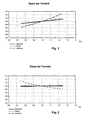
- Figure 1 is a representation of the relative speed, the motor current and the Recording power of a brushless fan drive without speed control (Prior art), depending on the relative supply voltage.
- Figure 2 is a representation of the relative speed, the motor current and the Recording power of a brushless fan drive with speed control (Prior art), depending on the relative supply voltage.
- Figure 3 is an illustration of the relative speed, the motor current and the Recording power of a brushless fan drive with speed control according to the invention as a function of the relative supply voltage.
- FIG. 4 shows by way of example the course of the PWM control signal at a Supply voltage, which is significantly higher than the nominal Supply voltage of the fan drive.
- FIG. 5 shows an example of the course of the PWM control signal at nominal Supply voltage.
- the rotational speed is a solid line, the current as close dash line and the performance as a wide dotted line over the tension shown. It was each at rated speed, rated current and rated power and normalized to nominal voltage.
- Figure 2 shows a representation of relative speed, motor current and Recording power of a brushless fan drive with speed control according to the prior art, depending on the relative Supply voltage. Also at supply voltages, by the Nominal voltage differ, remain speed and recording power due to the speed limitation constant.
- FIG. 3 shows the characteristics of a fan drive according to the invention.
- a motor control is used, the Motor current via pulse width modulation (PWM) controls and the speed limits a fixed maximum speed.
- PWM pulse width modulation
- the important thing is that the engine or the motor control is dimensioned so that the nominal Speed at nominal load at nominal supply voltage is reached, with the maximum duty cycle is almost reached.
- Figure 4 shows schematically the PWM control signal at a Supply voltage well above the nominal Supply voltage.
- the speed controller increases this PWM ratio.
- FIG. 5 schematically shows the PWM control signal at a slightly greater supply voltage than the nominal supply voltage. If the supply voltage continues to drop, the duty cycle can no longer or hardly be increased.
- the inventive dimensioning can be realized in many cases with a corresponding winding design. That is, the magnetic circuit and the commutation electronics do not need to be changed.
- One possible way of designing the winding design according to the invention is as follows:
Landscapes
- Engineering & Computer Science (AREA)
- Power Engineering (AREA)
- Control Of Motors That Do Not Use Commutators (AREA)
Abstract
Description
Die Erfindung betrifft ein Verfahren zur Ansteuerung eines bürstenlosen
Elektromotors nach dem Oberbegriff des Patentanspruchs 1.The invention relates to a method for controlling a brushless
Electric motor according to the preamble of
Es sind bürstenlose Gleichstrommotoren für Lüfteranwendungen bekannt, die mit oder ohne eine Drehzahlregelung (closed-loop control) arbeiten.Brushless DC motors for fan applications are known operate with or without a closed-loop control.
Die Drehzahl eines bürstenlosen Gleichstrommotors ohne Drehzahlregelung
ist abhängig von der Versorgungsspannung (siehe Figur 1). Je höher die
Versorgungsspannung ist, desto höher ist die Drehzahl des Motors.
Bei einigen Anwendungen, zum Beispiel in Fahrzeugen, werden
Lüftermotoren mit einer nominalen Versorgungsspannung von 12 V
verwendet. Die Bordspannung der Fahrzeuge kann aber in einem Bereich von
8 V bis 18 V variieren, so dass auch die Drehzahl des Motors erheblich
schwanken kann. Bei Lüfteranwendungen steigt die abgegebene
mechanische Leistung etwa mit der dritten Potenz der Drehzahl. Mit
wachsender Versorgungsspannung wächst die Drehzahl des ungeregelten
Motors. Damit wächst auch die Motorbelastung und daher kann bei einer zu
hohen Versorgungsspannung leicht eine thermische Überbelastung des
Motors auftreten.The speed of a brushless DC motor without speed control is dependent on the supply voltage (see Figure 1). The higher the supply voltage, the higher the speed of the motor.
In some applications, for example in vehicles, fan motors are used with a nominal supply voltage of 12V. The on-board voltage of the vehicles, however, can vary in a range of 8 V to 18 V, so that the speed of the engine can fluctuate considerably. In fan applications, the mechanical power output increases approximately at the third power of the speed. As the supply voltage increases, the speed of the uncontrolled motor increases. Thus, the engine load increases and therefore can easily occur at too high a supply voltage thermal overloading of the motor.
Wenn andere Parameter und Umwelteinflüsse vernachlässigt werden, zeigt
die untere Tabelle, wie sich die Drehzahländerung, hervorgerufen durch eine
Erhöhung der Versorgungsspannung, eines ungeregelten Elektromotors, der
als Lüftermotor eingesetzt wird, auf andere Motor- bzw. Lüfterparameter
auswirkt:
Bei höheren Drehzahlen liefert also der Lüfter mehr Luft, die jedoch vom Nutzer normalerweise nicht benötigt wird, da der Lüfter so ausgelegt ist, dass er im gesamten Versorgungsspannungsbereich eine ausreichende Luftmenge liefert. Zusätzlich wächst jedoch mit höherer Drehzahl sowohl die Belastung des Motors als auch das Geräusch des Lüfters. Die höhere Belastung bedeutet nicht nur einen höheren Energieverbrauch, sondern auch eine höhere Eigenerwärmung des Motors, die wiederum die Lebensdauer des Lagersystems negativ beeinflusst.At higher speeds, so the fan provides more air, but the User is not normally needed, because the fan is designed so that He in the entire supply voltage range, a sufficient amount of air supplies. In addition, however, the load increases with higher speed engine and noise of the fan. The higher load not only means higher energy consumption, but also one higher self-heating of the engine, which in turn increases the life of the engine Storage system negatively affected.
Bei Motoren mit Drehzahlregelung bleibt die Ausgangsleistung konstant (Figur
2). Daher führt eine Verringerung der Versorgungsspannung zu einer höheren
Stromaufnahme, so dass insbesondere die Leistungselektronik für diese
Ströme ausgelegt sein muss. Bei einem Motor mit aktiver Drehzahlregelung
bleiben Drehzahl, Motorabgabeleistung, Luftvolumen, Druckerhöhung und das
Lüftergeräusch unabhängig von der Versorgungsspannung konstant. In
diesem Fall wird der Motor so dimensioniert, dass er auch bei minimaler noch
erlaubter Versorgungsspannung die maximal gewünschte Drehzahl auch bei
maximaler Belastung erreichen kann. Probleme können jedoch bei Motoren
mit integrierter Kommutierungselektronik entstehen, da die
Leistungselektronik auch bei reduzierter Versorgungsspannung konstante
Leistung liefern muss und daher höhere Ströme aufnimmt, wie die folgende
Tabelle zeigt:
Wenn in dem oberen Beispiel die Spannung vom Nominalwert 12 V auf 8,4 V sinkt (-30%), wächst der Eingangsstrom der Leistungselektronik um ca. 43%. Dementsprechend stark wächst auch die Verlustleistung, das heißt die thermische Belastung der Leistungshalbleiter der Kommutierungselektronik.In the above example, when the voltage is from the nominal 12V to 8.4V decreases (-30%), the input current of the power electronics increases by approx. 43%. Accordingly, the power loss, that is the thermal load of the power semiconductors of the commutation electronics.
Eine Möglichkeit zur Vermeidung dieses Problems besteht darin, zusätzlich zur Drehzahlregelung die Versorgungsspannung durch die Motorsteuerung zu erfassen und eine entsprechende Anpassung des PWM-Verhältnisses vorzunehmen. Dadurch erhöhen sich aber die Kosten für die Sensorik. Eine solche Lösung kommt daher für Low-Cost-Motoren aus Kostengründen oftmals nicht in Frage.One way to avoid this problem is in addition for speed control the supply voltage through the motor control too capture and adjust the PWM ratio accordingly make. However, this increases the costs for the sensors. A Such a solution is therefore for low-cost engines for cost reasons Often out of the question.
Die Aufgabe der Erfindung ist es, ein Verfahren zur Ansteuerung eines bürstenlosen Elektromotors vorzuschlagen, bei dem weder bei reduzierter noch bei erhöhter Betriebsspannung eine erhöhte Belastung der Motorkomponenten entsteht.The object of the invention is to provide a method for controlling a brushless electric motor to propose in which neither at reduced even at elevated operating voltage increased load on Engine components is created.
Diese Aufgabe wird erfindungsgemäß durch die Merkmale des
Patentanspruch 1 gelöst. Ein bürstenloser Motor nach der Erfindung ist in
Anspruch 3 angegeben.This object is achieved by the features of
Grundlage der Lösung ist ein drehzahlgeregelter Motor, wobei jedoch auf eine Regelreserve im Unterspannungsbereich gemäß dem Stand der Technik verzichtet wird.Basis of the solution is a variable speed motor, but with a Control reserve in the low voltage range according to the prior art is waived.
Als Anwendung für den erfindungsgemäßen Elektromotor kommen beispielsweise neben Anwendungen als Pumpenmotoren insbesondere auch Lüftermotoren in Frage. As an application for the electric motor according to the invention for example, in addition to applications as pump motors in particular also Fan motors in question.
Erfindungsgemäß wird eine vorzugsweise auf Pulsweitenmodulation (PWM) basierende Motorsteuerung verwendet, die mit einer Drehzahlregelung arbeitet und so dimensioniert ist, dass der Motor seine vorgegebene nominale Drehzahl bei nominaler Belastung bei der nominalen Versorgungsspannung gerade erreicht. Steigt in diesem Fall die Versorgungsspannung über den nominalen Wert, so verhindert die Regelung eine Erhöhung der Drehzahl.According to the invention, a pulse width modulation (PWM) is preferably used. based engine control uses that with a speed control works and is dimensioned so that the motor its nominal nominal Speed at nominal load at nominal supply voltage just reached. In this case, the supply voltage rises above the nominal value, the control prevents an increase in the speed.
Sinkt die Versorgungsspannung unter die nominale Spannung bei voller Motorbelastung, erreicht die Regelung schnell das maximale PWM-Verhältnis. Ab diesem Punkt kann das PWM-Verhältnis nicht weiter erhöht werden, weshalb auch der Eingangsstrom nicht weiter ansteigen kann. Statt dessen dreht sich der Motor durch die reduzierte Spannung bei dadurch ebenfalls zurückgehender Stromaufnahme langsamer und es reduziert sich auch die Motorbelastung (Verlustleistung).If the supply voltage drops below the nominal voltage at full Motor load, the control quickly reaches the maximum PWM ratio. At this point, the PWM ratio can not be further increased, which is why the input current can not increase any further. Instead The motor also rotates due to the reduced voltage decreasing current consumption slower and it also reduces the Motor load (power loss).
Nachfolgend wird ein Ausführungsbeispiel der Erfindung im Vergleich zum Stand der Technik anhand der Zeichnungen näher beschrieben.Hereinafter, an embodiment of the invention in comparison to Prior art described in more detail with reference to the drawings.
Figur 1 ist eine Darstellung der relativen Drehzahl, des Motorstroms und der Aufnahmeleistung eines bürstenlosen Lüfterantriebes ohne Drehzahlregelung (Stand der Technik), in Abhängigkeit der relativen Versorgungsspannung.Figure 1 is a representation of the relative speed, the motor current and the Recording power of a brushless fan drive without speed control (Prior art), depending on the relative supply voltage.
Figur 2 ist eine Darstellung der relativen Drehzahl, des Motorstrom und der Aufnahmeleistung eines bürstenlosen Lüfterantriebes mit Drehzahlregelung (Stand der Technik), in Abhängigkeit der relativen Versorgungsspannung.Figure 2 is a representation of the relative speed, the motor current and the Recording power of a brushless fan drive with speed control (Prior art), depending on the relative supply voltage.
Figur 3 ist eine Darstellung der relativen Drehzahl, des Motorstroms und der Aufnahmeleistung eines bürstenlosen Lüfterantriebes mit Drehzahlregelung gemäß der Erfindung in Abhängigkeit der relativen Versorgungsspannung. Figure 3 is an illustration of the relative speed, the motor current and the Recording power of a brushless fan drive with speed control according to the invention as a function of the relative supply voltage.
Figur 4 zeigt beispielhaft den Verlauf des PWM-Steuersignals bei einer Versorgungsspannung, die deutlich höher ist als die nominale Versorgungsspannung des Lüfterantriebs.FIG. 4 shows by way of example the course of the PWM control signal at a Supply voltage, which is significantly higher than the nominal Supply voltage of the fan drive.
Figur 5 zeigt beispielhaft den Verlauf des PWM-Steuersignals bei nominaler Versorgungsspannung.FIG. 5 shows an example of the course of the PWM control signal at nominal Supply voltage.
In den Figuren 1 bis 3 ist die Drehzahl als durchgezogene Linie, der Strom als enge Strichlinie und die Leistung als weite Strichlinie über der Spannung dargestellt. Es wurde jeweils auf Nenndrehzahl, Nennstrom und Nennleistung sowie auf Nennspannung normiert.In Figures 1 to 3, the rotational speed is a solid line, the current as close dash line and the performance as a wide dotted line over the tension shown. It was each at rated speed, rated current and rated power and normalized to nominal voltage.
Figur 1 zeigt eine Darstellung von relativer Drehzahl, Motorstrom und Aufnahmeleistung (Nominalwert = 1,0) eines bürstenlosen Lüfterantriebes ohne Drehzahlregelung nach dem Stand der Technik, in Abhängigkeit der relativen Versorgungsspannung (Nominalwert = 1,0). Man erkennt, dass alle Werte sich mit steigender Versorgungsspannung etwa linear erhöhen.FIG. 1 shows a representation of relative speed, motor current and Recording power (nominal value = 1.0) of a brushless fan drive without speed control according to the prior art, depending on relative supply voltage (nominal value = 1.0). You realize that all Values increase approximately linearly with increasing supply voltage.
Die Folge ist ein höherer Energieverbrauch, höhere Verluste im Motor und in der Kommutierungselektronik sowie ein erhöhtes Strömungsgeräusch, insbesondere wenn die Versorgungsspannung höher ist als die Nominalspannung (1,0).The result is a higher energy consumption, higher losses in the engine and in the commutation electronics and increased flow noise, especially when the supply voltage is higher than that Nominal voltage (1.0).
Figur 2 zeigt eine Darstellung von relativer Drehzahl, Motorstrom und Aufnahmeleistung eines bürstenlosen Lüfterantriebes mit Drehzahlregelung nach dem Stand der Technik, in Abhängigkeit der relativen Versorgungsspannung. Auch bei Versorgungsspannungen, die von der Nominalspannung abweichen, bleiben Drehzahl und Aufnahmeleistung aufgrund der Drehzahlbegrenzung konstant. Figure 2 shows a representation of relative speed, motor current and Recording power of a brushless fan drive with speed control according to the prior art, depending on the relative Supply voltage. Also at supply voltages, by the Nominal voltage differ, remain speed and recording power due to the speed limitation constant.
Bei niederen Versorgungsspannungen unterhalb der Nominalspannung (=1,0) erhöht sich der Motorstrom. Die Folge ist eine höhere Strombelastung für die Kommutierungselektronik und für die Zuleitungen.At low supply voltages below the nominal voltage (= 1.0) the motor current increases. The result is a higher current load for the Commutation electronics and for the supply lines.
Figur 3 zeigt die Kennlinien eines erfindungsgemäßen Lüfterantriebs. Zur Ansteuerung des Elektromotors wird eine Motorsteuerung verwendet, die den Motorstrom mittels Pulsweitenmodulation (PWM) steuert und die Drehzahl auf eine festgelegte maximale Drehzahl begrenzt. Wichtig ist, dass der Motor beziehungsweise die Motorsteuerung so dimensioniert ist, dass die nominale Drehzahl bei nominaler Belastung bei der nominalen Versorgungsspannung gerade erreicht wird, wobei das maximale Tastverhältnis nahezu erreicht ist.FIG. 3 shows the characteristics of a fan drive according to the invention. to Control of the electric motor, a motor control is used, the Motor current via pulse width modulation (PWM) controls and the speed limits a fixed maximum speed. The important thing is that the engine or the motor control is dimensioned so that the nominal Speed at nominal load at nominal supply voltage is reached, with the maximum duty cycle is almost reached.
Die Darstellung der relativen Drehzahl, des Motorstroms und der
Aufnahmeleistung eines erfindungsgemäßen Motors in Abhängigkeit der
relativen Versorgungsspannung gemäß Figur 3 zeigt, dass bei
Versorgungsspannungen größer als die Nominalspannung Drehzahl und
Aufnahmeleistung aufgrund der Drehzahlbegrenzung konstant bleiben.
Dabei nimmt der Motorstrom ab und bleibt unkritisch. Bei
Versorgungsspannungen kleiner als die Nominalspannung nehmen Drehzahl
und Aufnahmeleistung ab, da der Motorstrom aufgrund des bereits bei seiner
Nennspannung erreichten maximalen PWM-Verhältnisses nicht erhöht werden
kann.The representation of the relative speed, the motor current and the power consumption of a motor according to the invention in dependence on the relative supply voltage of Figure 3 shows that remain constant at supply voltages greater than the nominal voltage speed and power due to the speed limit.
The motor current decreases and remains uncritical. With supply voltages smaller than the nominal voltage, speed and power consumption decrease because the motor current can not be increased due to the maximum PWM ratio already reached at its nominal voltage.
Aus Figur 3 erkennt man auch, dass der Motorstrom im nominalen
Arbeitspunkt (Position 1,0 / 1,0) sein Maximum erreicht.From Figure 3 it can be seen that the motor current in the nominal
Operating point (
Figur 4 zeigt schematisch das PWM-Steuersignal bei einer Versorgungsspannung deutlich oberhalb der nominalen Versorgungsspannung.Figure 4 shows schematically the PWM control signal at a Supply voltage well above the nominal Supply voltage.
Reduziert man die Versorgungsspannung, so erhöht der Drehzahlregler das PWM-Verhältnis. If the supply voltage is reduced, the speed controller increases this PWM ratio.
Die Figur 5 zeigt schematisch das PWM-Steuersignal bei einer geringfügig
größeren Versorgungsspannung als die nominale Versorgungsspannung.
Sinkt die Versorgungsspannung weiter ab, so kann das Tastverhältnis nicht
mehr oder kaum noch erhöht werden.
Die erfindungsgemäße Dimensionierung kann man in vielen Fällen mit einer
entsprechenden Wicklungsauslegung verwirklichen. Das heißt, der
magnetische Kreis und die Kommutierungselektronik müssen nicht geändert
werden. Ein möglicher Weg, die erfindungsgemäße Wicklungsauslegung
auszugestalten, sieht folgendermaßen aus:FIG. 5 schematically shows the PWM control signal at a slightly greater supply voltage than the nominal supply voltage. If the supply voltage continues to drop, the duty cycle can no longer or hardly be increased.
The inventive dimensioning can be realized in many cases with a corresponding winding design. That is, the magnetic circuit and the commutation electronics do not need to be changed. One possible way of designing the winding design according to the invention is as follows:
Beispielsweise werde ein Lüfter mit einem Mustermotor mit bekannter
Wicklungsauslegung (Drahtdurchmesser d0, Windungszahl pro Zahn N0)
untersucht. Der Lüfter kann entweder in die tatsächliche Applikation eingebaut
werden, oder in eine Prüfvorrichtung, die eine ähnliche strömungstechnische
Widerstandskennlinie aufweist wie die tatsächliche Applikation. In diesem Fall
erreicht man bei der nominalen Drehzahl den nominalen Arbeitspunkt
(Luftmenge und Druck). Experimentell kann diejenige Versorgungsspannung
festgestellt werden, bei welcher der Motor gerade noch diese nominale
Drehzahl erreicht. Wenn diese Grenzwert UGrenze bekannt ist und die nominale
Versorgungsspannung UNenn ist, dann kann die erfindungsgemäße Wicklung
einfach berechnet werden durch:
- Us U s
- Versorgungsspannungsupply voltage
- tt
- ZeitTime
- PWMPWM
- PulsweitenmodulationPulse Width Modulation
- UNenn U nominal
- Nominale VersorgungsspannungNominal supply voltage
- UGrenze U border
- Grenzspannunglimit voltage
- N, NoN, No
- Windungszahlnumber of turns
- d, d0 d, d 0
- DrahtdurchmesserWire diameter
Claims (7)
dadurch gekennzeichnet, dass der Motor so dimensioniert ist, dass die nominale Drehzahl im nominalen Arbeitspunkt bei der nominalen Versorgungsspannung und bei maximalem PWM-Verhältnis gerade erreicht wird.Brushless electric motor for operation within a predetermined supply voltage range, wherein a motor control is provided which controls the winding voltage by means of pulse width modulation (PWM) and controls the speed to a fixed maximum speed,
characterized in that the motor is dimensioned so that the nominal speed is just reached in the nominal operating point at the nominal supply voltage and maximum PWM ratio.
Applications Claiming Priority (2)
| Application Number | Priority Date | Filing Date | Title |
|---|---|---|---|
| DE102004019004A DE102004019004A1 (en) | 2004-04-20 | 2004-04-20 | Method for controlling a brushless electric motor |
| DE102004019004 | 2004-04-20 |
Publications (1)
| Publication Number | Publication Date |
|---|---|
| EP1589652A1 true EP1589652A1 (en) | 2005-10-26 |
Family
ID=34934844
Family Applications (1)
| Application Number | Title | Priority Date | Filing Date |
|---|---|---|---|
| EP05007611A Withdrawn EP1589652A1 (en) | 2004-04-20 | 2005-04-07 | Method for controlling a brushless DC motor |
Country Status (4)
| Country | Link |
|---|---|
| US (1) | US7095189B2 (en) |
| EP (1) | EP1589652A1 (en) |
| JP (1) | JP2005312292A (en) |
| DE (1) | DE102004019004A1 (en) |
Cited By (2)
| Publication number | Priority date | Publication date | Assignee | Title |
|---|---|---|---|---|
| WO2008095565A1 (en) * | 2007-02-05 | 2008-08-14 | Robert Bosch Gmbh | Fan arrangement with better availibility, and method for operation thereof |
| RU2366069C1 (en) * | 2007-12-24 | 2009-08-27 | Общество с ограниченной ответственностью "Научно-исследовательский институт механотронных технологий-Альфа-Научный Центр" (ООО "НИИМЕХАНОТРОНИКИ-АЛЬФА-НЦ") | Rectifier drive |
Families Citing this family (6)
| Publication number | Priority date | Publication date | Assignee | Title |
|---|---|---|---|---|
| US20070205731A1 (en) * | 2006-03-01 | 2007-09-06 | Regal-Beloit Corporation | Methods and systems for dynamically braking an electronically commutated motor |
| JP4687730B2 (en) * | 2008-03-06 | 2011-05-25 | パナソニック株式会社 | Blower and electric device equipped with the same |
| DE102009041878A1 (en) | 2009-09-07 | 2011-03-10 | C. & E. Fein Gmbh | Controllable DC motor with modified characteristic curve |
| US9735720B2 (en) * | 2012-09-07 | 2017-08-15 | Ford Global Technologies, Llc | Electric motor torque control |
| DE102012220223A1 (en) * | 2012-11-07 | 2014-05-08 | Robert Bosch Gmbh | Method for operating electric power tool e.g. lawn mower, involves controlling electric motor by pulse width modulation, and driving electric motor alternately with preset duty cycle and specific duty cycle |
| RU2658678C1 (en) * | 2017-05-25 | 2018-06-22 | Зао "Нии Механотроники-Альфа-Нц" | Contact-free dc drive |
Citations (4)
| Publication number | Priority date | Publication date | Assignee | Title |
|---|---|---|---|---|
| US5563980A (en) * | 1994-12-14 | 1996-10-08 | Industrial Technology Research Institute | Brushless DC motor speed controller |
| EP0802613A2 (en) * | 1996-04-16 | 1997-10-22 | PM DM Precision Motors Deutsche Minebea GmbH | Multi-phase, brushless DC motor |
| EP0899862A2 (en) * | 1997-08-28 | 1999-03-03 | Barber Colman | Systems and methods for actuator power failure response |
| EP1383232A2 (en) * | 2002-07-16 | 2004-01-21 | Robert Bosch Gmbh | Method for improving availability of a fan system |
Family Cites Families (17)
| Publication number | Priority date | Publication date | Assignee | Title |
|---|---|---|---|---|
| US3870860A (en) * | 1973-03-15 | 1975-03-11 | Emerson Electric Co | Floor drop-in forced circulation electric space heater |
| US5075608A (en) * | 1974-06-24 | 1991-12-24 | Erdman David M | Control system, electronically commutated motor system, draft inducer apparatus and method |
| US4843532A (en) * | 1988-07-01 | 1989-06-27 | General Electric Company | Regulating pulse width modulator for power supply with high speed shutoff |
| JPH06165571A (en) * | 1992-11-18 | 1994-06-10 | Matsushita Electric Ind Co Ltd | Brushless motor controller |
| DE19647983A1 (en) * | 1995-12-04 | 1997-06-05 | Papst Motoren Gmbh & Co Kg | Physical variable control method and device e.g. for electronically commutated electric motor |
| US6040668A (en) * | 1996-11-14 | 2000-03-21 | Telcom Semiconductor, Inc. | Monolithic fan controller |
| US5963706A (en) * | 1997-10-23 | 1999-10-05 | Baik; Edward Hyeen | Control system for multi-phase brushless DC motor |
| JPH11334630A (en) * | 1998-05-22 | 1999-12-07 | Koyo Seiko Co Ltd | Power steering unit |
| JPH11341877A (en) * | 1998-05-22 | 1999-12-10 | Tamiya Inc | Electric motor speed controller |
| WO2001020762A1 (en) | 1999-09-15 | 2001-03-22 | Robert Bosch Gmbh | Electronically commutated motor |
| DE10044742A1 (en) * | 1999-09-15 | 2001-04-19 | Bosch Gmbh Robert | Electronically commutated motor |
| WO2001020766A1 (en) * | 1999-09-16 | 2001-03-22 | Delphi Technologies, Inc. | Minimization of motor torque ripple due to unbalanced conditions |
| AU2001284010A1 (en) * | 2000-08-30 | 2002-03-13 | Papst-Motoren Gmbh And Co. Kg | Fan arrangement |
| KR100434236B1 (en) * | 2001-10-11 | 2004-06-04 | 페어차일드코리아반도체 주식회사 | A motor control driving circuit |
| US6762636B1 (en) * | 2001-12-11 | 2004-07-13 | Cypress Semiconductor Corp. | Circuit and method for adjusting duty cycle of a high speed, low swing output signal |
| US6650074B1 (en) * | 2002-05-29 | 2003-11-18 | Dell Products, L.P. | Fan speed controller with conditioned tachometer signal |
| US7692399B2 (en) * | 2003-04-01 | 2010-04-06 | Hewlett-Packard Development Company, L.P. | DC motor control |
-
2004
- 2004-04-20 DE DE102004019004A patent/DE102004019004A1/en not_active Withdrawn
-
2005
- 2005-04-07 EP EP05007611A patent/EP1589652A1/en not_active Withdrawn
- 2005-04-11 US US11/103,295 patent/US7095189B2/en not_active Expired - Lifetime
- 2005-04-13 JP JP2005115515A patent/JP2005312292A/en not_active Withdrawn
Patent Citations (4)
| Publication number | Priority date | Publication date | Assignee | Title |
|---|---|---|---|---|
| US5563980A (en) * | 1994-12-14 | 1996-10-08 | Industrial Technology Research Institute | Brushless DC motor speed controller |
| EP0802613A2 (en) * | 1996-04-16 | 1997-10-22 | PM DM Precision Motors Deutsche Minebea GmbH | Multi-phase, brushless DC motor |
| EP0899862A2 (en) * | 1997-08-28 | 1999-03-03 | Barber Colman | Systems and methods for actuator power failure response |
| EP1383232A2 (en) * | 2002-07-16 | 2004-01-21 | Robert Bosch Gmbh | Method for improving availability of a fan system |
Cited By (3)
| Publication number | Priority date | Publication date | Assignee | Title |
|---|---|---|---|---|
| WO2008095565A1 (en) * | 2007-02-05 | 2008-08-14 | Robert Bosch Gmbh | Fan arrangement with better availibility, and method for operation thereof |
| US8628310B2 (en) | 2007-02-05 | 2014-01-14 | Robert Bosch Gmbh | Fan system having improved availability and method for its operation |
| RU2366069C1 (en) * | 2007-12-24 | 2009-08-27 | Общество с ограниченной ответственностью "Научно-исследовательский институт механотронных технологий-Альфа-Научный Центр" (ООО "НИИМЕХАНОТРОНИКИ-АЛЬФА-НЦ") | Rectifier drive |
Also Published As
| Publication number | Publication date |
|---|---|
| JP2005312292A (en) | 2005-11-04 |
| US20050231139A1 (en) | 2005-10-20 |
| DE102004019004A1 (en) | 2005-11-24 |
| US7095189B2 (en) | 2006-08-22 |
Similar Documents
| Publication | Publication Date | Title |
|---|---|---|
| DE3342031B4 (en) | Circuit arrangement for speed control of an electric motor | |
| DE102009041878A1 (en) | Controllable DC motor with modified characteristic curve | |
| DE10158994A1 (en) | Motor for altering heating and cooling capacity of piston compressor e.g. for refrigeration unit, has variable number of coil windings | |
| DE10231452A1 (en) | Fan control system using a micro controller | |
| DE102013003512B4 (en) | Power supply in an on-board network for a compressor in an air supply system | |
| EP1683259B1 (en) | Electronically commutated motor and method for controlling the same | |
| DE102007050844A1 (en) | Booster power circuit | |
| EP1589652A1 (en) | Method for controlling a brushless DC motor | |
| DE102004062032A1 (en) | Circuit arrangement for rapid reduction of an induced current | |
| EP3257134B1 (en) | Method for operating an active converter connected to an electric maschine and device for its implementation | |
| DE10121766A1 (en) | power unit | |
| DE102011088976A1 (en) | Arrangement for controlling an electric vacuum pump | |
| WO2008086909A1 (en) | Regulating method for a volume flow regulation | |
| DE102008011224A1 (en) | Generator device with overvoltage monitoring | |
| DE202008006853U1 (en) | Electronically commutated DC motor with a pi-filter | |
| EP2680432B1 (en) | Method for controlling a stepper motor | |
| EP1473824A2 (en) | Control unit for driving a transistor controlled fan arrangement | |
| DE102008041236A1 (en) | Drive device operating method for multiple-fan arrangement of passenger motor vehicle, involves operating electric motors in operating mode, where operating mode is scheduled starting from total output of multiple-fan arrangement | |
| DE102009056802B4 (en) | Control electronics for an electromagnetically actuated valve for operating a hydrostatic displacement unit | |
| DE102010018777A1 (en) | Energy supply system for an electrical consumer in a motor vehicle | |
| DE102013200248A1 (en) | Method for designing control transmitter system with electric motor for use in e.g. seat adjuster in motor vehicle, involves adjusting controlling of electric motor for each function of applications, using configuration parameter | |
| EP1784911B1 (en) | Circuit arrangement and method for operating an electric motor with varying rotational speed at a constant-voltage source | |
| EP1322024A2 (en) | Selfcontrolled power level adaptation | |
| EP1228563A1 (en) | Electronically commutable motor | |
| DE102004001879A1 (en) | Operating method for a step-up chopper for increasing output voltage compared to input voltage uses a choke and a controlled switch element for turning a switching current on and off via the choke |
Legal Events
| Date | Code | Title | Description |
|---|---|---|---|
| PUAI | Public reference made under article 153(3) epc to a published international application that has entered the european phase |
Free format text: ORIGINAL CODE: 0009012 |
|
| AK | Designated contracting states |
Kind code of ref document: A1 Designated state(s): AT BE BG CH CY CZ DE DK EE ES FI FR GB GR HU IE IS IT LI LT LU MC NL PL PT RO SE SI SK TR |
|
| AX | Request for extension of the european patent |
Extension state: AL BA HR LV MK YU |
|
| 17P | Request for examination filed |
Effective date: 20051112 |
|
| AKX | Designation fees paid |
Designated state(s): DE FI IT |
|
| STAA | Information on the status of an ep patent application or granted ep patent |
Free format text: STATUS: THE APPLICATION IS DEEMED TO BE WITHDRAWN |
|
| 18D | Application deemed to be withdrawn |
Effective date: 20100220 |