EP1589641A2 - Brushless dc motor and method for aligning the sensing device in a brushless dc motor - Google Patents
Brushless dc motor and method for aligning the sensing device in a brushless dc motor Download PDFInfo
- Publication number
- EP1589641A2 EP1589641A2 EP05007907A EP05007907A EP1589641A2 EP 1589641 A2 EP1589641 A2 EP 1589641A2 EP 05007907 A EP05007907 A EP 05007907A EP 05007907 A EP05007907 A EP 05007907A EP 1589641 A2 EP1589641 A2 EP 1589641A2
- Authority
- EP
- European Patent Office
- Prior art keywords
- stator
- motor
- sensor device
- rotor
- relative
- Prior art date
- Legal status (The legal status is an assumption and is not a legal conclusion. Google has not performed a legal analysis and makes no representation as to the accuracy of the status listed.)
- Withdrawn
Links
Images


Classifications
-
- H—ELECTRICITY
- H02—GENERATION; CONVERSION OR DISTRIBUTION OF ELECTRIC POWER
- H02K—DYNAMO-ELECTRIC MACHINES
- H02K29/00—Motors or generators having non-mechanical commutating devices, e.g. discharge tubes or semiconductor devices
- H02K29/06—Motors or generators having non-mechanical commutating devices, e.g. discharge tubes or semiconductor devices with position sensing devices
- H02K29/08—Motors or generators having non-mechanical commutating devices, e.g. discharge tubes or semiconductor devices with position sensing devices using magnetic effect devices, e.g. Hall-plates, magneto-resistors
-
- H—ELECTRICITY
- H02—GENERATION; CONVERSION OR DISTRIBUTION OF ELECTRIC POWER
- H02K—DYNAMO-ELECTRIC MACHINES
- H02K15/00—Processes or apparatus specially adapted for manufacturing, assembling, maintaining or repairing of dynamo-electric machines
Definitions
- the invention relates generally to the field of brushless DC motors and More specifically, a method for adjusting a sensor device in a brushless DC motor.
- Such motors can be used in a wide variety of technical fields come, for example in the automotive technology for drives in support of the Steering, the braking system or as motors for pumps or blowers.
- Other Applications include fan blowers in power supplies, drive motors in industrial machinery etc., just to name a few examples.
- An electronically commutated, brushless DC motor basically includes a Shaft, a rotor assembly that has one or more arranged on the shaft Permanent magnets comprises, and a stator assembly comprising a stator body and Has phase windings, which with the magnetic poles of the rotor in Interaction stand.
- Two bearings are arranged at an axial distance on the shaft to To store the rotor assembly and the stator assembly relative to each other.
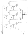
- Fig. 1 shows a schematic diagram of a drive electronics for a three-phase DC motor.
- the DC motor comprises three phase windings U, 12; V, 14; W 16, which are shown in Fig. 1 schematically in star connection 10.
- the three windings 12, 14, 16 are between a positive supply rail 18 and a negative one Supply rail 20 connected.
- the positive supply rail 18 performs this Potential + U, and the negative supply rail 20 carries the potential -U.
- the Phase windings 12, 14, 16 become conductive over six power switching devices T1 to T6 Subject of control signals to the supply rails 18, 20 connected.
- the power switching components T1 to T6 are e.g. Power transistors. They have control connections that in Fig. 1 are designated G1 to G6.
- the control connections correspond in particular to the Gates of the power transistors.
- suitable control signals to the gates of the Power transistors become the phase windings 12 to 16 of the DC motor energized to control its operation.
- Method of controlling a brushless electronically commutated DC motor are described for example in DE 10033561 A1 and U.S. Pat. 6,400,109 B1, to which reference is made. Accordingly, one is Arrangement of the three windings in a delta connection possible (not graphically ) Shown.
- Hall sensors are often used to detect the rotor position, which are attached to a fixed support member in the DC motor and with Control magnets interact.
- the control magnets may be on an end face of the rotor attached separate control magnets or by the working magnets of the rotor itself be formed.
- For detecting the rotational position of the rotor can be used for a three-phase DC motor, for example, three Hall sensors by 120 ° (electrically) out of phase the circumference of the motor shaft can be arranged.
- the Hall sensors generate depending on the rotor rotation rotational position signals, which make it possible, the necessary Commutation signals for switching the energization of the individual phase windings derive. For this purpose, however, it is necessary that the position of the Hall sensors in relation to the stator poles is set correctly.
- the Hall sensors are often applied to a circuit board, the for example, on a flange of the DC motor, the front side of the rotor is attached opposite.
- a circuit board the for example, on a flange of the DC motor, the front side of the rotor is attached opposite.
- the average current consumption of the motor in Dependence on the relative position between the circuit board, which the Hall sensors carries, and the stator determined.
- the relative position of the PCB and thus of the Hall sensors to the stator is set so that the current consumption of the motor is minimal.
- circuit board or a circuit board holding carrier component such as a flange
- a circuit board holding carrier component such as a flange
- the PCB and the support member in the motor housing difficult to access.
- a support flange is not round but polygonal and due mechanical conditions can not be rotated arbitrarily.
- the invention provides a brushless DC motor with a stator, a rotor, a control magnet, which is rotatably connected to the rotor, and a Sensor device connected to the control magnet for generating a commutation signal interacts.
- the sensor device is arranged on a carrier component which is in or on the housing of the DC motor is mounted stationary.
- a Holding device for receiving the stator provided with the support member connected and rotatable relative to the support member to the position of the Sensor device on the support member relative to the stator to adjust.
- a DC motor is created in which the sensor device mounted stationary is, while the stator can be rotated relative to the sensor device to the position of the To adjust sensors.
- a pipe piece is preferably provided for this purpose as a holding device, in which the stator is introduced.
- the stator may be in the pipe section, for example glued or otherwise held in it.
- This piece of pipe can be part of the Form housing of the DC motor and is rotatable relative to the support member held.
- the support member by a Flange of the DC motor is formed, which has a centering collar for receiving the Pipe piece to hold the pipe piece in the flange rotatably.
- the DC motor according to the invention has suitable fastening means, such as Grub screws or the like, on.
- the support member by a flange with polygonal and in particular square outer contour formed to a second Flange on the opposite end of the engine is aligned; the sensor device is applied to a printed circuit board which is attached to this flange.
- the sensor device adjusted relative to the stator can be without twisting the sensor device and thus the flange, because otherwise the two flanges would no longer be aligned.
- the sensor device on a separate carrier in the interior the housing of the DC motor applied after assembly of the DC motor is difficult to access so that also for this design Adjustment of the sensor device according to the invention by turning the stator is advantageous.
- the sensor device preferably comprises Hall sensors, for example in a three-phase DC motor three at an angle of 120 ° (electric) staggered Hall sensors.
- the control magnets can by the working magnets of the rotor or by separate control magnets, for example, on an end face of the rotor are positioned to be formed.
- Fig. 1 shows a schematic circuit diagram of a Control electronics for a three-phase DC motor.
- the transistors T1 to T6 over their gates G1 to G6 are controlled.
- the control times are determined by the Output signals of the sensor device, which is adjusted according to the invention.
- Fig. 2 shows the induced voltages of a three-phase DC motor with block-shaped energization or commutation, wherein the induced voltages of the three Phases are denoted by u, v and w respectively.
- Fig. 2 is an electrical cycle of 360 ° of Energization phase shown.
- Fig. 3 shows an external view of an embodiment of the DC motor according to the invention. Shown in Fig. 3 are a housing tube 21, which at its two front ends by a first flange 22 and a second flange 24 is completed. On the side of the first Flange 22 are signal lines 26 and connections for the power supply 28 of DC motor led out, and on the side of the second flange 24 is the Output end of the shaft 30 shown.
- FIG. 6 the housing tube 21 held in the flanges 22, 24 via a centering collar 32, wherein in Fig. 6, only the output side end of the DC motor with the flange 24 is shown.
- the Connection between housing tube 21 and flange 22 at the other end of the engine corresponds to the illustration of FIG. 6 in mirror image.
- this is Housing tube 21 is pushed onto the centering collar 32 and can by means of a Fixing device 34, fixed in the embodiment shown a grub screw become.
- a groove 36 is formed in the vicinity of the front end of the housing tube 21, in which the grub screw 34 engages.
- a stator body 38 and the phase winding 40 applied thereon which in the Housing tube 20 are held, shown.
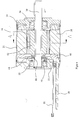
- the DC motor according to the invention is described in more detail in the Sectional view of Fig. 4 shown.
- a rotor body or - Wegschluß 42 applied, which carries one or more permanent magnets 44.
- the Permanent magnets 44 may be embedded in the rotor core permanent magnets or a annular, multi-pole magnetized permanent magnet or several individual on the Rotor core 42 applied permanent magnets.
- the rotor body 42 also carries on a Front end a control magnet 46 in the form of an annular magnetic track, which in Correspondence with the permanent magnet 44 with alternating polarity is magnetized.
- the sensor device is formed in the embodiment shown by Hall sensors 48, which are applied to a printed circuit board 50.
- a printed circuit board 50 In one embodiment of the invention is a Three-phase DC motor provided, the sensor device three by 120 ° (electrically) phase-shifted Hall sensors.
- the printed circuit board 50 is annular configured, arranged around the shaft 30 and held on a support. In the preferred embodiment of the invention, this support is formed by the flange 22.
- the flanges 22 and 24 also serve to receive bearings 52, 54 for supporting the Shaft 30 to allow rotation of the rotor 42, 44 relative to the stator 38, 40.
- control magnets 46 are rotatably with the rotor 42, 44, while the sensor device 48, in particular Hall sensors, are fixed in position in the housing of the DC motor.
- the stator 38, 40 is in the Housing tube 21 and held together with the housing tube 21 relative to the fixed flanges 22, 24 rotatable to the relative position of sensors 48 and stator 38, 40 to adjust.
- Fig. 5 shows a cross-sectional view through the DC motor of Fig. 3 and 4 along the line A-A in Fig. 4.
- the stator body 38 comprises a annular stator yoke 56, from the individual stator hammers 58 radially inward protrude.
- the stator hammers 58 form the poles of the stator and carry phase windings 40, which are not shown in Fig. 5.
- the stator surrounds the rotor 42 and the Permanent magnets 44 of the rotor coaxial.
- the rotor 42 consists of individual radially magnetized permanent magnets 44, which on the Rotor body 42 are pushed axially and are held by grooves, each between two adjacent magnets 44 are configured on the outer circumference of the rotor body 42. These grooves act at especially large speeds of the engine occurring against centrifugal forces.
- the rotor body 42 consists of stanzlast notorious ferromagnetic sheets.
- the rotor body 42 facing side of the permanent magnets 44 is preferably even.
- the rotor body 42 consists of a cylindrical body having a substantially N-sided base, where N is the number of rotor magnets 44th corresponds, and with N grooves, respectively at the edges of the cylindrical rotor body 42nd are formed.
- the sensor device 48 is adjusted in the DC motor according to the invention as follows.
- An excitation current is applied to the stator windings 40 in order to first rotate the rotor 42, 44 in one direction, eg counterclockwise (left-hand rotation).
- the engine is preferably operated at idle.
- the average current consumption I 0 is determined as a function of the angle of rotation ⁇ between the flange 22, which carries the Hall sensors 48, and the stator body 38.
- the housing tube 21 is rotated stepwise together with the stator 38, 40 relative to the flange 22 to change the angle of rotation ⁇ between the Hall sensors 48 and the stator 38, 40 and at each angular step, the average current consumption I 0 of Engage motor.
- the mean current consumption I 0 as a function of the angle of rotation ⁇ is shown in FIG. 7 for the left-hand rotation through the curve 60, the curve 60 having a relative minimum at the angle ⁇ 1 .
- a corresponding curve 62 of the mean current consumption I 0 is determined for the clockwise rotation of the motor. This has a relative minimum at the angle ⁇ 2 , wherein in general the angles of rotation ⁇ 1 and ⁇ 2 are different.
- the cause for the deviation between the angles ⁇ 1 and ⁇ 2 lies in the mechanical tolerances of the motor structure, in particular tolerances of the permanent magnets of the rotor and the stator segments, as well as positional tolerances of the Hall sensors on the circuit board and an eccentricity of the circuit board relative to the flange, Etc.
- an optimum setting angle between Hall sensors and stator is preferably determined as an angle ⁇ 0 , which is determined between the two for the respective directions of rotation of the Motor optimal angles ⁇ 1 and ⁇ 2 is located.
- the optimum adjustment angle ⁇ 0 is determined either as a geometrical average between ⁇ 1 and ⁇ 2 or as the intersection of the two curves 60 and 62.
Landscapes
- Engineering & Computer Science (AREA)
- Power Engineering (AREA)
- Manufacturing & Machinery (AREA)
- Brushless Motors (AREA)
Abstract
Die Erfindung betrifft einen bürstenlosen Gleichstrommotor mit einem Stator, einem Rotor, einem Steuermagneten, der mit dem Rotor drehfest verbunden ist, einer Sensorvorrichtung, die mit dem Steuermagneten zur Erzeugung eines Kommutierungssignals zusammenwirkt, wenigstens einem Trägerbauteil, das die Sensorvorrichtung trägt, und einer Haltevorrichtung zum Aufnehmen des Stators, die mit dem Trägerbauteil verbunden und relativ zu dem Trägerbauteil verdrehbar ist, um die Lage der Sensorvorrichtung relativ zu dem Stator zu justieren.The invention relates to a brushless DC motor with a stator, a rotor, a control magnet, which is rotatably connected to the rotor, a sensor device, which cooperates with the control magnet to generate a commutation signal, at least one support component, which carries the sensor device, and a holding device for receiving the stator, which is connected to the support member and relative to the Carrier member is rotatable to the position of the sensor device relative to the stator to adjust.
Description
Die Erfindung betrifft allgemein das Gebiet der bürstenlosen Gleichstrommotoren und spezieller ein Verfahren zum Justieren einer Sensorvorrichtung in einem bürstenlosen Gleichstrommotor.The invention relates generally to the field of brushless DC motors and More specifically, a method for adjusting a sensor device in a brushless DC motor.
Solche Motoren können in unterschiedlichsten technischen Bereichen zur Anwendung kommen, beispielsweise in der Automobiltechnik für Antriebe zur Unterstützung der Lenkung, des Bremssystems oder als Motoren für Pumpen oder Gebläse. Andere Anwendungsbereich sind Lüftergebläse in Netzteilen, Antriebsmotoren in Industriemaschinen etc., um nur einige wenige Beispiele zu nennen.Such motors can be used in a wide variety of technical fields come, for example in the automotive technology for drives in support of the Steering, the braking system or as motors for pumps or blowers. Other Applications include fan blowers in power supplies, drive motors in industrial machinery etc., just to name a few examples.
Ein elektronisch kommutierter, bürstenloser Gleichstrommotor umfaßt grundsätzlich eine Welle, eine Rotorbaugruppe, die einen oder mehrere auf der Welle angeordnete Permanentmagnete umfaßt, und eine Statorbaugruppe, die einen Statorkörper und Phasenwicklungen aufweist, welche mit den magnetischen Polen des Rotors in Wechselwirkung stehen. Zwei Lager sind in axialem Abstand an der Welle angeordnet, um die Rotorbaugruppe und die Statorbaugruppe relativ zueinander zu lagern.An electronically commutated, brushless DC motor basically includes a Shaft, a rotor assembly that has one or more arranged on the shaft Permanent magnets comprises, and a stator assembly comprising a stator body and Has phase windings, which with the magnetic poles of the rotor in Interaction stand. Two bearings are arranged at an axial distance on the shaft to To store the rotor assembly and the stator assembly relative to each other.
Fig. 1 zeigt ein schematisches Schaltbild einer Ansteuerelektronik für einen dreiphasigen
Gleichstrommotor. Der Gleichstrommotor umfaßt drei Phasenwicklungen U, 12; V, 14; W,
16, die in Fig. 1 schematisch in Sternschaltung 10 dargestellt sind. Die drei Wicklungen 12,
14, 16 sind zwischen einer positiven Versorgungsschiene 18 und einer negativen
Versorgungsschiene 20 angeschlossen. Die positive Versorgungsschiene 18 führt das
Potential +U, und die negative Versorgungsschiene 20 führt das Potential -U. Die
Phasenwicklungen 12, 14, 16 werden über sechs Leistungs-Schaltbauteile T1 bis T6 nach
Maßgabe von Steuersignalen mit den Versorgungsschienen 18, 20 verbunden. Die Leistungs-Schaltbauteile
T1 bis T6 sind z.B. Leistungstransistoren. Sie weisen Steueranschlüsse auf, die
in Fig. 1 mit G1 bis G6 bezeichnet sind. Die Steueranschlüsse entsprechen insbesondere den
Gates der Leistungstransistoren. Durch Anlegen geeigneter Steuersignale an die Gates der
Leistungstransistoren werden die Phasenwicklungen 12 bis 16 des Gleichstrommotors
bestromt, um dessen Betrieb zu steuern. Verfahren zum Steuern eines bürstenlosen
elektronisch kommutierten Gleichstrommotors sind beispielsweise beschrieben in DE
10033561 A1 und U.S. 6,400,109 B1, auf die Bezug genommen wird. Entsprechend ist eine
Anordnung der drei Wicklungen in einer Dreieckschaltung möglich (nicht zeichnerisch
dargestellt).Fig. 1 shows a schematic diagram of a drive electronics for a three-phase
DC motor. The DC motor comprises three phase windings U, 12; V, 14;
Bei Gleichstrommotoren, insbesondere dreiphasigen Gleichstrommotoren wie sie in industriellen Anwendungen und in der Automobiltechnik zum Einsatz kommen, unterscheidet man zwischen einer "blockförmigen" und einer "sinusförmigen" Bestromung der Phasen des Motors. "Blockförmige" Bestromung bedeutet, daß der Strom, der an die Phasenwicklungen angelegt wird, einen rechteckförmigen Verlauf hat. Der Strom wird zu einem Zeitpunkt auf einen gegebenen Wert eingeschaltet und zu einem anderen Zeitpunkt wieder abgeschalt. Solche Motoren haben üblicherweise eine trapezförmige induzierte Spannung. Fig. 2 zeigt schematisch die induzierten Spannungen eines "blockförmig" bestromten oder "blockkommutierten" Motors. Im Betrieb sollte die Umschaltung der Phasenströme dann erfolgen, wenn sich jeweils zwei induzierte Spannungen schneiden, um eine minimale Drehmomentwelligkeit zu erzeugen. Hierzu wird eine Information über die jeweilige Rotorlage benötigt, um die Phasenströme zum richtigen Zeitpunkt umzuschalten.In DC motors, especially three-phase DC motors as in industrial applications and used in automotive technology differs one between a "block-shaped" and a "sinusoidal" energization of the phases of Engine. "Block-shaped" energization means that the current flowing to the phase windings is created, has a rectangular course. The electricity is going on at a time switched on a given value and switched off again at another time. Such motors usually have a trapezoidal induced voltage. Fig. 2 shows schematically the induced voltages of a "block-shaped" energized or "block commutated" engine. In operation, the switching of the phase currents should then occur when two induced voltages intersect, by a minimum To generate torque ripple. For this purpose, information about the respective Rotor position required to switch the phase currents at the right time.
Im Stand der Technik werden zur Erfassung der Rotorlage häufig Hall-Sensoren eingesetzt, die an einem feststehenden Trägerbauteil in dem Gleichstrommotor angebracht sind und mit Steuermagneten zusammenwirken. Die Steuermagnete können an einer Stirnseite des Rotors angebrachte separate Steuermagnete sein oder durch die Arbeitsmagnete des Rotors selbst gebildet werden. Zur Erfassung der Drehlage des Rotors können für einen dreiphasigen Gleichstrommotor beispielsweise drei Hall-Sensoren um 120° (elektrisch) phasenversetzt um den Umfang der Motorwelle angeordnet werden. Die Hall-Sensoren erzeugen abhängig von der Rotordrehung Drehlagesignale, welche es ermöglichen, die notwendigen Kommutierungssignale zum Umschalten der Bestromung der einzelnen Phasenwicklungen abzuleiten. Hierzu ist es jedoch notwendig, daß die Lage der Hallsensoren im Verhältnis zu den Statorpolen richtig eingestellt ist.In the prior art Hall sensors are often used to detect the rotor position, which are attached to a fixed support member in the DC motor and with Control magnets interact. The control magnets may be on an end face of the rotor attached separate control magnets or by the working magnets of the rotor itself be formed. For detecting the rotational position of the rotor can be used for a three-phase DC motor, for example, three Hall sensors by 120 ° (electrically) out of phase the circumference of the motor shaft can be arranged. The Hall sensors generate depending on the rotor rotation rotational position signals, which make it possible, the necessary Commutation signals for switching the energization of the individual phase windings derive. For this purpose, however, it is necessary that the position of the Hall sensors in relation to the stator poles is set correctly.
In der Praxis sind die Hall-Sensoren häufig auf einer Leiterplatte aufgebracht, die beispielsweise an einem Flansch des Gleichstrommotors, der Stirnseite des Rotors gegenüberliegend befestigt ist. Bei dem Zusammenbau des Gleichstrommotors muß darauf geachtet werden, daß die Lage der Hall-Sensoren im Verhältnis zu den Polen des Stators richtig eingestellt ist. Die Einstellung und Justierung der relativen Lage kann wie folgt durchgeführt werden:In practice, the Hall sensors are often applied to a circuit board, the for example, on a flange of the DC motor, the front side of the rotor is attached opposite. When assembling the DC motor must be on it Care must be taken that the position of the Hall sensors in relation to the poles of the stator is set correctly. The adjustment and adjustment of the relative position can be as follows be performed:
Während des Betriebs des Gleichstrommotors wird die mittlere Stromaufnahme des Motors in Abhängigkeit von der relativen Lage zwischen der Leiterplatte, welche die Hall-Sensoren trägt, und dem Stator ermittelt. Die relative Lage der Leiterplatte und somit der Hall-Sensoren zu dem Stator wird so eingestellt, daß die Stromaufnahme des Motors minimal ist.During operation of the DC motor, the average current consumption of the motor in Dependence on the relative position between the circuit board, which the Hall sensors carries, and the stator determined. The relative position of the PCB and thus of the Hall sensors to the stator is set so that the current consumption of the motor is minimal.
Nach dem Justieren der Leiterplatte ist es möglich, aus den Drehlagesignalen der Hall-Sensoren die Rotorlage relativ zu dem Stator zu bestimmen und abhängig davon die gewünschten Kommutierungssignale abzuleiten.After adjusting the circuit board, it is possible from the rotational position signals of the Hall sensors determine the rotor position relative to the stator and depending on the derive desired commutation signals.
In der Praxis ist es jedoch nicht immer möglich, die Leiterplatte bzw. ein die Leiterplatte haltendes Trägerbauteil, wie einen Flansch, beliebig zu verdrehen. Beispielsweise können die Leiterplatte und das Trägerbauteil im Motorgehäuse schwer zugänglich sein. Es ist auch denkbar, daß ein Trägerflansch nicht rund, sondern mehreckig ausgestaltet ist und aufgrund mechanischer Gegebenheiten nicht beliebig gedreht werden kann.In practice, however, it is not always possible, the circuit board or a circuit board holding carrier component, such as a flange, to twist as desired. For example, the PCB and the support member in the motor housing difficult to access. It is also conceivable that a support flange is not round but polygonal and due mechanical conditions can not be rotated arbitrarily.
Es ist die Aufgabe der Erfindung, einen bürstenlosen Gleichstrommotor anzugeben, in dem eine Sensorvorrichtung problemlos justiert werden kann.It is the object of the invention to provide a brushless DC motor in which a sensor device can be easily adjusted.
Diese Aufgabe wird durch einen bürstenlosen Gleichstrommotor mit den Merkmalen von Patentanspruch 1 (sowie durch ein Verfahren mit den Merkmalen von Patentanspruch 12) gelöst.This task is accomplished by a brushless DC motor with the characteristics of Claim 1 (and by a method having the features of claim 12) solved.
Die Erfindung sieht einen bürstenlosen Gleichstrommotor vor, mit einem Stator, einem Rotor, einem Steuermagneten, der mit dem Rotor drehfest verbunden ist, und einer Sensorvorrichtung, die mit dem Steuermagneten zur Erzeugung eines Kommutierungssignals zusammenwirkt. Die Sensorvorrichtung ist auf einem Trägerbauteil angeordnet, das in oder an dem Gehäuse des Gleichstrommotors ortsfest montiert ist. Erfindungsgemäß ist eine Haltevorrichtung zum Aufnehmen des Stators vorgesehen, die mit dem Trägerbauteil verbunden und relativ zu dem Trägerbauteil verdrehbar ist, um die Lage der Sensorvorrichtung auf dem Trägerbauteil relativ zu dem Stator zu justieren. Erfindungsgemäß wird somit ein Gleichstrommotor geschaffen, in dem die Sensorvorrichtung ortsfest montiert ist, während der Stator relativ zur Sensorvorrichtung verdreht werden kann, um die Lage der Sensoren zu justieren. Bei dem erfindungsgemäßen Gleichstrommotor ist es somit möglich, eine im Motorgehäuse, insbesondere an einem Motorflansch, fest montierte Sensorvorrichtung vorzusehen und gleichwohl noch diese Sensorvorrichtung in ihrer Lage relativ zum Stator zu justieren, indem nicht die Sensoren, sondern der Stator gedreht wird. Erfindungsgemäß wird hierzu als Haltevorrichtung vorzugsweise ein Rohrstück vorgesehen, in welches der Stator eingebracht wird. Der Stator kann in dem Rohrstück beispielsweise eingeklebt oder auf andere Weise darin gehalten sein. Dieses Rohrstück kann Teil des Gehäuses des Gleichstrommotors bilden und wird relativ zu dem Trägerbauteil drehbar gehalten. In einer bevorzugten Ausführung der Erfindung wird das Trägerbauteil durch einen Flansch des Gleichstrommotors gebildet, der einen Zentrierbund zum Aufnehmen des Rohrstücks aufweist, um das Rohrstück in dem Flansch drehbar zu halten.The invention provides a brushless DC motor with a stator, a rotor, a control magnet, which is rotatably connected to the rotor, and a Sensor device connected to the control magnet for generating a commutation signal interacts. The sensor device is arranged on a carrier component which is in or on the housing of the DC motor is mounted stationary. According to the invention is a Holding device for receiving the stator provided with the support member connected and rotatable relative to the support member to the position of the Sensor device on the support member relative to the stator to adjust. According to the invention Thus, a DC motor is created in which the sensor device mounted stationary is, while the stator can be rotated relative to the sensor device to the position of the To adjust sensors. In the DC motor according to the invention it is thus possible a permanently mounted in the motor housing, in particular on a motor flange Provide sensor device and still this sensor device in their position relative to the stator to adjust by not the sensors, but the stator is rotated. According to the invention, a pipe piece is preferably provided for this purpose as a holding device, in which the stator is introduced. The stator may be in the pipe section, for example glued or otherwise held in it. This piece of pipe can be part of the Form housing of the DC motor and is rotatable relative to the support member held. In a preferred embodiment of the invention, the support member by a Flange of the DC motor is formed, which has a centering collar for receiving the Pipe piece to hold the pipe piece in the flange rotatably.
Um die Sensorvorrichtung in ihrer Lage relativ zum Stator nach der Justierung zu fixieren, weist der erfindungsgemäße Gleichstrommotor geeignete Befestigungsmittel, wie Madenschrauben oder dergleichen, auf.In order to fix the sensor device in its position relative to the stator after the adjustment, the DC motor according to the invention has suitable fastening means, such as Grub screws or the like, on.
In einer Ausführung der Erfindung wird das Trägerbauteil durch einen Flansch mit polygonaler und insbesondere quadratischer Außenkontur gebildet, der zu einem zweiten Flansch auf der gegenüberliegenden Stirnseite des Motors fluchtet; die Sensorvorrichtung ist auf eine Leiterplatte aufgebracht, welche an diesem Flansch befestigt ist. In dieser Ausführung ist es besonders günstig, wenn die Sensorvorrichtung relativ zum Stator justiert werden kann, ohne die Sensorvorrichtung und somit den Flansch zu verdrehen, weil ansonsten die beiden Flansche nicht mehr miteinander fluchten würden. In einer anderen Ausführung der Erfindung ist die Sensorvorrichtung auf einem separaten Träger im Inneren des Gehäuses des Gleichstrommotors aufgebracht, der nach der Montage des Gleichstrommotors schwer zugänglich ist, so daß auch für diese Ausführung die erfindungsgemäße Justierung der Sensorvorrichtung durch Drehen des Stators vorteilhaft ist.In one embodiment of the invention, the support member by a flange with polygonal and in particular square outer contour formed to a second Flange on the opposite end of the engine is aligned; the sensor device is applied to a printed circuit board which is attached to this flange. In this Embodiment, it is particularly advantageous if the sensor device adjusted relative to the stator can be without twisting the sensor device and thus the flange, because otherwise the two flanges would no longer be aligned. In another Embodiment of the invention is the sensor device on a separate carrier in the interior the housing of the DC motor applied after assembly of the DC motor is difficult to access, so that also for this design Adjustment of the sensor device according to the invention by turning the stator is advantageous.
Erfindungsgemäß umfaßt die Sensorvorrichtung vorzugsweise Hall-Sensoren, beispielsweise bei einem dreiphasigen Gleichstrommotor drei in einem Winkel von 120° (elektrisch) versetzte Hall-Sensoren. Die Steuermagnete können durch die Arbeitsmagnete des Rotors oder durch separate Steuermagnete, die beispielsweise an einer Stirnseite des Rotors positioniert sind, gebildet sein.According to the invention, the sensor device preferably comprises Hall sensors, for example in a three-phase DC motor three at an angle of 120 ° (electric) staggered Hall sensors. The control magnets can by the working magnets of the rotor or by separate control magnets, for example, on an end face of the rotor are positioned to be formed.
Die Erfindung ist im folgenden anhand einer bevorzugten Ausführung mit Bezug auf die Zeichnungen näher erläutert.The invention is based on a preferred embodiment with reference to the Drawings explained in more detail.
In den Figuren zeigen:
- Fig. 1
- ein Schaltbild einer Ansteuerelektronik für einen dreiphasigen Gleichstrommotor;
- Fig. 2
- den Verlauf der induzierten Spannungen eines blockförmig bestromten dreiphasigen Gleichstrommotors;
- Fig. 3
- eine schematische Außenansicht eines Gleichstrommotors gemäß der Erfindung;
- Fig. 4
- eine Längsschnittdarstellung durch den Gleichstrommotor der Fig. 3;
- Fig. 5
- eine Querschnittdarstellung durch den Gleichstrommotor der Fig. 3 und 4 entlang der Linie A-A;
- Fig. 6
- eine Teilschnittdarstellung durch den Elektromotor der Fig. 3 und 4 entlang der Linie C-C; und
- Fig. 7
- einen Graphen des Motorstroms abhängig von der Justierung der Sensorvorrichtung zur Erläuterung des erfindungsgemäßen Verfahrens.
- Fig. 1
- a circuit diagram of a control electronics for a three-phase DC motor;
- Fig. 2
- the course of the induced voltages of a block-fed three-phase DC motor;
- Fig. 3
- a schematic external view of a DC motor according to the invention;
- Fig. 4
- a longitudinal sectional view through the DC motor of Fig. 3;
- Fig. 5
- a cross-sectional view through the DC motor of Figure 3 and 4 along the line AA.
- Fig. 6
- a partial sectional view through the electric motor of Figures 3 and 4 along the line CC ..; and
- Fig. 7
- a graph of the motor current depending on the adjustment of the sensor device for explaining the method according to the invention.
Fig. 1, die bereits beschrieben wurde, zeigt ein schematisches Schaltbild einer
Ansteuerelektronik für einen dreiphasigen Gleichstrommotor. Zur Bestromung der drei
Phasen U 12, V 14 und W 16 des Gleichstrommotors werden die Transistoren T1 bis T6, über
ihre Gates G1 bis G6 angesteuert. Die Steuerzeitpunkte werden bestimmt durch die
Ausgangssignale der Sensorvorrichtung, die erfindungsgemäß justiert ist.Fig. 1, which has already been described, shows a schematic circuit diagram of a
Control electronics for a three-phase DC motor. For energizing the three
Fig. 2 zeigt die induzierten Spannungen eines dreiphasigen Gleichstrommotors mit blockförmiger Bestromung oder Kommutierung, wobei die induzierten Spannungen der drei Phasen mit u, v bzw. w bezeichnet sind. In Fig. 2 ist ein elektrischer Zyklus von 360° der Bestromungsphase dargestellt. Fig. 2 shows the induced voltages of a three-phase DC motor with block-shaped energization or commutation, wherein the induced voltages of the three Phases are denoted by u, v and w respectively. In Fig. 2 is an electrical cycle of 360 ° of Energization phase shown.
Fig. 3 zeigt eine Außenansicht einer Ausführung des erfindungsgemäßen Gleichstrommotors.
In Fig. 3 dargestellt sind ein Gehäuserohr 21, das an seinen beiden Stirnenden durch einen
ersten Flansch 22 und einen zweiten Flansch 24 abgeschlossen ist. Auf der Seite des ersten
Flansches 22 sind Signalleitungen 26 und Anschlüsse für die Stromversorgung 28 des
Gleichstrommotors herausgeführt, und auf der Seite des zweiten Flansches 24 ist das
Abtriebsende der Welle 30 dargestellt.Fig. 3 shows an external view of an embodiment of the DC motor according to the invention.
Shown in Fig. 3 are a
Wie in der vergrößerten Teilschnittdarstellung der Fig. 6 zu erkennen, ist das Gehäuserohr 21
in den Flanschen 22, 24 über einen Zentrierbund 32 gehalten, wobei in Fig. 6 nur das
abtriebsseitige Ende des Gleichstrommotors mit dem Flansch 24 dargestellt ist. Die
Verbindung zwischen Gehäuserohr 21 und Flansch 22 an dem anderen Stirnende des Motors
entspricht der Darstellung der Fig. 6 spiegelbildlich. Wie in Fig. 6 zu sehen, ist das
Gehäuserohr 21 auf den Zentrierbund 32 aufgeschoben und kann daran mittels einer
Fixiervorrichtung 34, bei der gezeigten Ausführungsform eine Madenschraube, fixiert
werden. Hierzu ist in der Nähe des Stirnendes des Gehäuserohrs 21 eine Nut 36 ausgebildet,
in welche die Madenschraube 34 eingreift. In der Darstellung der Fig. 6 sind ferner ein Teil
eines Statorkörpers 38 und der darauf aufgebrachten Phasenwicklung 40, welche in dem
Gehäuserohr 20 gehalten werden, dargestellt.As can be seen in the enlarged partial sectional view of FIG. 6, the
Der erfindungsgemäße Gleichstrommotor ist mit weiteren Einzelheiten in der
Schnittdarstellung der Fig. 4 gezeigt. Auf die Welle 30 ist ein Rotorkörper oder -rückschluß
42 aufgebracht, welcher einen oder mehrere Permanentmagnete 44 trägt. Die
Permanentmagnete 44 können in dem Rotorkern eingebettete Permanentmagnete oder ein
ringförmiger, mehrpolig magnetisierter Permanentmagnet oder mehrere einzelne auf den
Rotorkern 42 aufgebrachte Permanentmagnete sein. Der Rotorkörper 42 trägt ferner an einem
Stirnende einen Steuermagneten 46 in Form einer ringförmigen Magnetbahn, die in
Übereinstimmung mit dem/den Permanentmagneten 44 mit wechselnder Polarität
magnetisiert ist. Sofern der/die Permanentmagnete 44, welche als Arbeitsmagnete dienen, ein
ausreichend starkes Magnetfeld erzeugen, können diese zusätzlich die Funktion der
Steuermagnete zum Abgeben von Drehlagesignalen an die Sensorvorrichtung übernehmen.
Die Sensorvorrichtung wird bei der gezeigten Ausführung durch Hall-Sensoren 48 gebildet,
welche auf eine Leiterplatte 50 aufgebracht sind. In einer Ausführung der Erfindung ist ein
dreiphasiger Gleichstrommotor vorgesehen, wobei die Sensorvorrichtung drei um 120°
(elektrisch) phasenversetzte Hall-Sensoren aufweist. Die Leiterplatte 50 ist ringförmig
ausgestaltet, um die Welle 30 herum angeordnet und auf einem Träger gehalten. In der
bevorzugten Ausführung der Erfindung wird dieser Träger durch den Flansch 22 gebildet.The DC motor according to the invention is described in more detail in the
Sectional view of Fig. 4 shown. On the
Die Flansche 22 und 24 dienen ferner zum Aufnehmen von Lagern 52, 54 zur Lagerung der
Welle 30, um eine Drehung des Rotors 42, 44 relativ zu dem Stator 38, 40 zu ermöglichen.The
Bei dem erfindungsgemäßen Gleichstrommotor sind somit die Steuermagnete 46 drehfest mit
dem Rotor 42, 44 verbunden, während die Sensorvorrichtung 48, insbesondere Hall-Sensoren,
in dem Gehäuse des Gleichstrommotors in ihrer Lage fixiert sind. Der Stator 38, 40 ist in dem
Gehäuserohr 21 gehalten und zusammen mit dem Gehäuserohr 21 relativ zu den
feststehenden Flanschen 22, 24 verdrehbar, um die relative Lage von Sensoren 48 und Stator
38, 40 zu justieren.In the DC motor according to the invention thus the
Fig. 5 zeigt eine Querschnittdarstellung durch den Gleichstrommotor der Fig. 3 und 4 entlang
der Linie A-A in Fig. 4. In der Darstellung der Fig. 5 ist der Flansch 22 im Verhältnis zu dem
Statorkörper 38 und dem Rotorkörper 42 dargestellt. Der Statorkörper 38 umfaßt einen
ringförmigen Statorrückschluß 56, von dem einzelne Statorhämmer 58 radial nach innen
abstehen. Die Statorhämmer 58 bilden die Pole des Stators und tragen Phasenwicklungen 40,
welche in Fig. 5 nicht dargestellt sind. Der Stator umgibt den Rotor 42 und die
Permanentmagnete 44 des Rotors koaxial.Fig. 5 shows a cross-sectional view through the DC motor of Fig. 3 and 4 along
the line A-A in Fig. 4. In the illustration of Fig. 5, the
Der Rotor 42 besteht aus einzelnen radial magnetisierten Permanentmagneten 44, die auf den
Rotorkörper 42 axial aufgeschoben sind und von Nuten gehalten werden, die jeweils zwischen
zwei benachbarten Magneten 44 am äußeren Umfang des Rotorkörpers 42 ausgestaltet sind.
Diese Nuten wirken den bei insbesondere großen Drehzahlen des Motors auftretenden
Zentrifugalkräften entgegen. Vorzugsweise besteht der Rotorkörper 42 aus stanzpaketierten
ferromagnetischen Blechen.The
Weiterhin können die Permanentmagnete 44 auf dem Rotorkörper 42 mit Kunststoff
umspritzt sein. Die dem Rotorkörper 42 zugewandte Seite der Permanentmagnete 44 ist
vorzugsweise eben. Entsprechend besteht der Rotorkörper 42 aus einem zylindrischen Körper
mit im wesentlichen N-eckiger Grundfläche, wobei N der Anzahl der Rotormagnete 44
entspricht, und mit N Nuten, die jeweils an den Kanten des zylindrischen Rotorkörpers 42
angeformt sind.Furthermore, the
Die Sensorvorrichtung 48 wird in dem erfindungsgemäßen Gleichstrommotor wie folgt
justiert. Auf die Statorwicklungen 40 wird ein Erregerstrom aufgeschaltet, um den Rotor 42,
44 zunächst in eine Richtung, z.B. gegen den Uhrzeigersinn (Linkslauf) zu drehen. Dabei
wird der Motor vorzugsweise im Leerlauf betrieben. Während des Linkslaufs wird die
mittlere Stromaufnahme I0 in Abhängigkeit von dem Verdrehwinkel ϕ zwischen dem Flansch
22, welcher die Hall-Sensoren 48 trägt, und dem Statorkörper 38 ermittelt. Zu diesem Zweck
wird das Gehäuserohr 21 zusammen mit dem Stator 38, 40 relativ zu dem Flansch 22
schrittweise verdreht, um den Verdrehwinkel ϕ zwischen den Hall-Sensoren 48 und dem
Stator 38, 40 zu verändern und bei jedem Winkelschritt die mittlere Stromaufnahme I0 des
Motors zu erfassen. Der untersuchte Verdrehwinkel ϕ durchläuft dabei einen Winkelbereich
von 360° geteilt durch die Anzahl der magnetischen Polpaare des Rotors, bei der gezeigten
Ausführung 360° / 8 = 45°. Die mittlere Stromaufnahme I0 in Abhängigkeit von dem
Verdrehwinkel ϕ ist in Fig. 7 für den Linkslauf durch die Kurve 60 dargestellt, wobei die
Kurve 60 bei dem Winkel ϕ1 ein relatives Minimum aufweist. Eine entsprechende Kurve 62
der mittleren Stromaufnahme I0 wird für den Rechtslauf des Motors ermittelt. Diese hat ein
relatives Minimum bei dem Winkel ϕ2, wobei im allgemeinen die Verdrehwinkel ϕ1 und ϕ2
unterschiedlich sind. Die Ursache für die Abweichung zwischen den Winkeln ϕ1 und ϕ2 liegt
in den mechanischen Toleranzen des Motoraufbaus, insbesondere Toleranzen der
Permanentmagnete des Rotors sowie der Statorsegmente, sowie Lagetoleranzen der Hall-Sensoren
auf der Leiterplatte sowie einer Exzentrizität der Leiterplatte relativ zu dem Flansch,
etc.The
Während die Verdrehwinkel ϕ1 und ϕ2 als im wesentlichen optimal für den Linkslauf bzw.
den Rechtslauf bezeichnet werden können, wird vorzugsweise ein optimaler Einstellwinkel
zwischen Hall-Sensoren und Stator als ein Winkel ϕ0 bestimmt, der zwischen den beiden für
die jeweiligen Drehrichtungen des Motors optimalen Winkeln ϕ1 und ϕ2 liegt. Vorzugsweise
wird der optimale Einstellwinkel ϕ0 entweder als geometricher Mittelwert zwischen ϕ1 und ϕ2
oder als Schnittpunkt der beiden Kurven 60 und 62 bestimmt.While the angles of rotation φ 1 and φ 2 can be designated as substantially optimal for the left-hand rotation or the clockwise rotation, an optimum setting angle between Hall sensors and stator is preferably determined as an angle φ 0 , which is determined between the two for the respective directions of rotation of the Motor optimal angles φ 1 and φ 2 is located. Preferably, the optimum adjustment angle φ 0 is determined either as a geometrical average between φ 1 and φ 2 or as the intersection of the two
In der gefundenen Position wird das Gehäuserohr 21 an den Flanschen 22, 24 mit Hilfe der
Madenschrauben fixiert, wie in Fig. 6 dargestellt. Sobald die Sensorvorrichtung justiert ist,
können die relative Lage von Stator und Rotor bestimmt und die gewünschten
Kommutierungssignale abgeleitet werden.In the found position, the
Die in der vorstehenden Beschreibung, den Ansprüchen und den Zeichnungen offenbarten Merkmale können sowohl einzeln als auch in beliebiger Kombination für die Verwirklichung der Erfindung in den verschiedenen Ausgestaltungen von Bedeutung sein. Those disclosed in the foregoing description, claims and drawings Features can be used individually as well as in any combination for the realization of the invention in the various embodiments of importance.
- 1010
- Sternschaltungstar connection
- 12, 14, 1612, 14, 16
- Wicklungenwindings
- 1818
- positive Versorgungsschienepositive supply rail
- 2020
- negative Versorgungsschienenegative supply rail
- 2121
- Gehäuserohrhousing tube
- 22, 2422, 24
- Flanschflange
- 2626
- Signalleitungensignal lines
- 2828
- Stromversorgungpower supply
- 3030
- Wellewave
- 3232
- Zentrierbundspigot
- 3434
- Fixiervorrichtungfixing
- 3636
- Nutgroove
- 3838
- Statorkörperstator
- 4040
- Phasenwicklungphase winding
- 4242
- Rotorkörper oder -rückschlußRotor body or back
- 4444
- Permanentmagnetepermanent magnets
- 4646
- Steuermagnetecontrol magnets
- 4848
- Hall-SensorenHall sensors
- 5050
- Leiterplattecircuit board
- 52, 5452, 54
- Kugellagerball-bearing
- 5656
- Statorrückschlußstator back
- 5858
- StatorhammerStatorhammer
- 60, 6260, 62
- Stromkurvencurrent curves
Claims (15)
einem Stator (38), einem Rotor (42),
einem Steuermagneten (46), der mit dem Rotor (42) drehfest verbunden ist,
einer Sensorvorrichtung (48), die mit dem Steuermagneten (46) zur Erzeugung eines Kommutierungssignals zusammenwirkt,
wenigstens einem Trägerbauteil (22), das die Sensorvorrichtung (48) trägt, und
einer Haltevorrichtung (21) zum Aufnehmen des Stators (38), die mit dem Trägerbauteil (22) verbunden und relativ zu dem Trägerbauteil (22) verdrehbar ist, um die Lage der Sensorvorrichtung (48) relativ zu dem Stator (38) zu justieren.Brushless DC motor with
a stator (38), a rotor (42),
a control magnet (46) which is rotatably connected to the rotor (42),
a sensor device (48) which cooperates with the control magnet (46) for generating a commutation signal,
at least one support component (22), which carries the sensor device (48), and
a holding device (21) for receiving the stator (38) connected to the support member (22) and rotatable relative to the support member (22) to adjust the position of the sensor device (48) relative to the stator (38).
Applications Claiming Priority (2)
| Application Number | Priority Date | Filing Date | Title |
|---|---|---|---|
| DE200410019636 DE102004019636B4 (en) | 2004-04-22 | 2004-04-22 | Brushless DC motor and method for adjusting a sensor device in a brushless DC motor |
| DE102004019636 | 2004-04-22 |
Publications (2)
| Publication Number | Publication Date |
|---|---|
| EP1589641A2 true EP1589641A2 (en) | 2005-10-26 |
| EP1589641A3 EP1589641A3 (en) | 2006-10-04 |
Family
ID=34934994
Family Applications (1)
| Application Number | Title | Priority Date | Filing Date |
|---|---|---|---|
| EP05007907A Withdrawn EP1589641A3 (en) | 2004-04-22 | 2005-04-11 | Brushless dc motor and method for aligning the sensing device in a brushless dc motor |
Country Status (2)
| Country | Link |
|---|---|
| EP (1) | EP1589641A3 (en) |
| DE (1) | DE102004019636B4 (en) |
Cited By (5)
| Publication number | Priority date | Publication date | Assignee | Title |
|---|---|---|---|---|
| WO2008104345A2 (en) | 2007-02-28 | 2008-09-04 | Sew-Eurodrive Gmbh & Co. Kg | Electric motor |
| WO2008104274A2 (en) | 2007-02-28 | 2008-09-04 | Sew-Eurodrive Gmbh & Co. Kg | Electric motor |
| WO2018184769A1 (en) * | 2017-04-07 | 2018-10-11 | Robert Bosch Gmbh | Rotor for a brushless direct-current motor, particularly for an electric motor of the inner rotor type, and electric motor comprising such a rotor |
| EP3599714A1 (en) * | 2018-07-24 | 2020-01-29 | BSH Hausgeräte GmbH | Method for determining the rotor position of a bldc motor |
| CN114726163A (en) * | 2021-01-04 | 2022-07-08 | 上海拜骋电器有限公司 | A brushless motor integrated control switch and electric tool |
Families Citing this family (2)
| Publication number | Priority date | Publication date | Assignee | Title |
|---|---|---|---|---|
| DE102004056990B4 (en) | 2004-11-25 | 2007-04-12 | Minebea Co., Ltd. | Electric machine, in particular brushless DC motor, and method for adjusting a sensor unit in an electric machine |
| DE102023119253A1 (en) * | 2023-07-20 | 2025-01-23 | Dr. Fritz Faulhaber GmbH & Co.KG | Assembly, in particular for an infusion pump, and method for assembly |
Family Cites Families (10)
| Publication number | Priority date | Publication date | Assignee | Title |
|---|---|---|---|---|
| NL7018060A (en) * | 1970-02-18 | 1971-08-20 | ||
| GB1576956A (en) * | 1976-11-01 | 1980-10-15 | Sony Corp | Brushless direct current motors |
| KR880002475B1 (en) * | 1985-08-21 | 1988-11-14 | 이이수 | D.c. multi-phase bi-polar brushless motor |
| JPS63240358A (en) * | 1987-03-25 | 1988-10-06 | Yaskawa Electric Mfg Co Ltd | Brushless motor encoder adjustment mechanism |
| DE3813064A1 (en) * | 1988-04-19 | 1989-11-02 | Heidolph Elektro Gmbh & Co Kg | Device for adjusting the rotor position identification system |
| DE3910498A1 (en) * | 1989-04-01 | 1990-10-04 | Schabmueller Antriebstechnik G | Tachogenerator having a rotor position transmitter for a three-phase servomotor with rotation-speed regulation and electronic commutation |
| JPH04250A (en) * | 1990-04-14 | 1992-01-06 | Matsushita Electric Works Ltd | Brushless motor |
| JPH09182403A (en) * | 1995-12-22 | 1997-07-11 | Nippon Seiko Kk | Brushless motor |
| CA2190697C (en) * | 1996-01-31 | 2000-07-25 | Donald Glenn Larson | Blower motor with adjustable timing |
| DE10033561B4 (en) * | 1999-07-14 | 2006-10-05 | Minebea Co., Ltd. | Electronically commutated motor with commutation signal |
-
2004
- 2004-04-22 DE DE200410019636 patent/DE102004019636B4/en not_active Expired - Fee Related
-
2005
- 2005-04-11 EP EP05007907A patent/EP1589641A3/en not_active Withdrawn
Cited By (7)
| Publication number | Priority date | Publication date | Assignee | Title |
|---|---|---|---|---|
| WO2008104345A2 (en) | 2007-02-28 | 2008-09-04 | Sew-Eurodrive Gmbh & Co. Kg | Electric motor |
| WO2008104274A2 (en) | 2007-02-28 | 2008-09-04 | Sew-Eurodrive Gmbh & Co. Kg | Electric motor |
| WO2008104274A3 (en) * | 2007-02-28 | 2008-11-20 | Sew Eurodrive Gmbh & Co | Electric motor |
| WO2008104345A3 (en) * | 2007-02-28 | 2008-11-20 | Sew Eurodrive Gmbh & Co | Electric motor |
| WO2018184769A1 (en) * | 2017-04-07 | 2018-10-11 | Robert Bosch Gmbh | Rotor for a brushless direct-current motor, particularly for an electric motor of the inner rotor type, and electric motor comprising such a rotor |
| EP3599714A1 (en) * | 2018-07-24 | 2020-01-29 | BSH Hausgeräte GmbH | Method for determining the rotor position of a bldc motor |
| CN114726163A (en) * | 2021-01-04 | 2022-07-08 | 上海拜骋电器有限公司 | A brushless motor integrated control switch and electric tool |
Also Published As
| Publication number | Publication date |
|---|---|
| DE102004019636A1 (en) | 2005-11-10 |
| DE102004019636B4 (en) | 2008-04-30 |
| EP1589641A3 (en) | 2006-10-04 |
Similar Documents
| Publication | Publication Date | Title |
|---|---|---|
| DE60311407T2 (en) | Electric power unit and power steering system | |
| DE60218935T2 (en) | Rotating electrical machine with three-phase ring coils and permanent magnets | |
| DE68919898T2 (en) | Permanent magnet-like synchronous motor. | |
| DE102009001173B4 (en) | Brushless motor | |
| EP2160816B1 (en) | Synchronous motor having 12 stator teeth and 10 rotor poles | |
| DE69500852T2 (en) | Three-phase brushless motor | |
| DE3632509C2 (en) | ||
| DE10033561B4 (en) | Electronically commutated motor with commutation signal | |
| DE10084652B4 (en) | Electric motor of the internal rotor type | |
| WO2010088983A1 (en) | Synchronous machine | |
| DE10335844B4 (en) | Rotary electric machine with a rotational position sensor and method for positioning the rotational position sensor | |
| DE102017223622A1 (en) | Rotor for an electric motor and electric motor | |
| EP2019471A2 (en) | Transversal flux machine | |
| DE1908579A1 (en) | Brushless and bearingless rotary field encoder | |
| DE102004019636B4 (en) | Brushless DC motor and method for adjusting a sensor device in a brushless DC motor | |
| EP0150070A2 (en) | Commutatorless direct-current motor with a ironless stator winding | |
| DE2425135A1 (en) | 6-POLE PERMANENT MAGNETIC ELECTRIC MOTOR | |
| DE112012004464T5 (en) | driving device | |
| EP1329015A1 (en) | Linear motor | |
| DE102007038902A1 (en) | Electrical power steering system has torque sensor and control device that is connected with torque sensor, and electro motor is connected with control unit | |
| EP1077359A2 (en) | Torsional angle measuring probe | |
| EP0501521B1 (en) | Brushless direct current motor for low speed | |
| DE3037724C2 (en) | DC motor | |
| DE102006032144A1 (en) | Brushless electric motor, has sensor generating rotor positioning signals suitable for finding absolute value of rotor position in dependent of ring rotation position, and device processing signals to form signal, which indicates position | |
| AT509030B1 (en) | METHOD FOR STARTING AND COMMUTING A BRUSHLESS DC MOTOR |
Legal Events
| Date | Code | Title | Description |
|---|---|---|---|
| PUAI | Public reference made under article 153(3) epc to a published international application that has entered the european phase |
Free format text: ORIGINAL CODE: 0009012 |
|
| AK | Designated contracting states |
Kind code of ref document: A2 Designated state(s): AT BE BG CH CY CZ DE DK EE ES FI FR GB GR HU IE IS IT LI LT LU MC NL PL PT RO SE SI SK TR |
|
| AX | Request for extension of the european patent |
Extension state: AL BA HR LV MK YU |
|
| PUAL | Search report despatched |
Free format text: ORIGINAL CODE: 0009013 |
|
| AK | Designated contracting states |
Kind code of ref document: A3 Designated state(s): AT BE BG CH CY CZ DE DK EE ES FI FR GB GR HU IE IS IT LI LT LU MC NL PL PT RO SE SI SK TR |
|
| AX | Request for extension of the european patent |
Extension state: AL BA HR LV MK YU |
|
| 17P | Request for examination filed |
Effective date: 20070213 |
|
| R17C | First examination report despatched (corrected) |
Effective date: 20070403 |
|
| AKX | Designation fees paid |
Designated state(s): AT BE BG CH CY CZ DE DK EE ES FI FR GB GR HU IE IS IT LI LT LU MC NL PL PT RO SE SI SK TR |
|
| R17C | First examination report despatched (corrected) |
Effective date: 20070403 |
|
| STAA | Information on the status of an ep patent application or granted ep patent |
Free format text: STATUS: THE APPLICATION IS DEEMED TO BE WITHDRAWN |
|
| 18D | Application deemed to be withdrawn |
Effective date: 20081103 |