EP1589630A2 - Protection for wind power station - Google Patents
Protection for wind power station Download PDFInfo
- Publication number
- EP1589630A2 EP1589630A2 EP05008695A EP05008695A EP1589630A2 EP 1589630 A2 EP1589630 A2 EP 1589630A2 EP 05008695 A EP05008695 A EP 05008695A EP 05008695 A EP05008695 A EP 05008695A EP 1589630 A2 EP1589630 A2 EP 1589630A2
- Authority
- EP
- European Patent Office
- Prior art keywords
- generator
- power grid
- choke
- electrical machine
- power
- Prior art date
- Legal status (The legal status is an assumption and is not a legal conclusion. Google has not performed a legal analysis and makes no representation as to the accuracy of the status listed.)
- Withdrawn
Links
- 230000005540 biological transmission Effects 0.000 claims abstract description 44
- 230000015556 catabolic process Effects 0.000 claims abstract description 22
- 230000001360 synchronised effect Effects 0.000 claims abstract description 22
- 230000008878 coupling Effects 0.000 claims description 10
- 238000010168 coupling process Methods 0.000 claims description 10
- 238000005859 coupling reaction Methods 0.000 claims description 10
- 230000011664 signaling Effects 0.000 claims 2
- 230000035939 shock Effects 0.000 description 8
- 230000000694 effects Effects 0.000 description 4
- 238000010586 diagram Methods 0.000 description 3
- 238000004519 manufacturing process Methods 0.000 description 2
- 238000012986 modification Methods 0.000 description 2
- 230000004048 modification Effects 0.000 description 2
- 230000005405 multipole Effects 0.000 description 2
- 235000001537 Ribes X gardonianum Nutrition 0.000 description 1
- 235000001535 Ribes X utile Nutrition 0.000 description 1
- 235000016919 Ribes petraeum Nutrition 0.000 description 1
- 244000281247 Ribes rubrum Species 0.000 description 1
- 235000002355 Ribes spicatum Nutrition 0.000 description 1
- 238000002485 combustion reaction Methods 0.000 description 1
- 230000001131 transforming effect Effects 0.000 description 1
Images

Classifications
-
- F—MECHANICAL ENGINEERING; LIGHTING; HEATING; WEAPONS; BLASTING
- F03—MACHINES OR ENGINES FOR LIQUIDS; WIND, SPRING, OR WEIGHT MOTORS; PRODUCING MECHANICAL POWER OR A REACTIVE PROPULSIVE THRUST, NOT OTHERWISE PROVIDED FOR
- F03D—WIND MOTORS
- F03D9/00—Adaptations of wind motors for special use; Combinations of wind motors with apparatus driven thereby; Wind motors specially adapted for installation in particular locations
- F03D9/20—Wind motors characterised by the driven apparatus
- F03D9/25—Wind motors characterised by the driven apparatus the apparatus being an electrical generator
- F03D9/255—Wind motors characterised by the driven apparatus the apparatus being an electrical generator connected to electrical distribution networks; Arrangements therefor
-
- H—ELECTRICITY
- H02—GENERATION; CONVERSION OR DISTRIBUTION OF ELECTRIC POWER
- H02J—CIRCUIT ARRANGEMENTS OR SYSTEMS FOR SUPPLYING OR DISTRIBUTING ELECTRIC POWER; SYSTEMS FOR STORING ELECTRIC ENERGY
- H02J3/00—Circuit arrangements for ac mains or ac distribution networks
- H02J3/38—Arrangements for parallely feeding a single network by two or more generators, converters or transformers
- H02J3/381—Dispersed generators
-
- H—ELECTRICITY
- H02—GENERATION; CONVERSION OR DISTRIBUTION OF ELECTRIC POWER
- H02J—CIRCUIT ARRANGEMENTS OR SYSTEMS FOR SUPPLYING OR DISTRIBUTING ELECTRIC POWER; SYSTEMS FOR STORING ELECTRIC ENERGY
- H02J3/00—Circuit arrangements for ac mains or ac distribution networks
- H02J3/38—Arrangements for parallely feeding a single network by two or more generators, converters or transformers
- H02J3/40—Synchronising a generator for connection to a network or to another generator
-
- F—MECHANICAL ENGINEERING; LIGHTING; HEATING; WEAPONS; BLASTING
- F05—INDEXING SCHEMES RELATING TO ENGINES OR PUMPS IN VARIOUS SUBCLASSES OF CLASSES F01-F04
- F05B—INDEXING SCHEME RELATING TO WIND, SPRING, WEIGHT, INERTIA OR LIKE MOTORS, TO MACHINES OR ENGINES FOR LIQUIDS COVERED BY SUBCLASSES F03B, F03D AND F03G
- F05B2270/00—Control
- F05B2270/10—Purpose of the control system
- F05B2270/107—Purpose of the control system to cope with emergencies
- F05B2270/1071—Purpose of the control system to cope with emergencies in particular sudden load loss
-
- H—ELECTRICITY
- H02—GENERATION; CONVERSION OR DISTRIBUTION OF ELECTRIC POWER
- H02J—CIRCUIT ARRANGEMENTS OR SYSTEMS FOR SUPPLYING OR DISTRIBUTING ELECTRIC POWER; SYSTEMS FOR STORING ELECTRIC ENERGY
- H02J2300/00—Systems for supplying or distributing electric power characterised by decentralized, dispersed, or local generation
- H02J2300/20—The dispersed energy generation being of renewable origin
- H02J2300/28—The renewable source being wind energy
-
- H—ELECTRICITY
- H02—GENERATION; CONVERSION OR DISTRIBUTION OF ELECTRIC POWER
- H02J—CIRCUIT ARRANGEMENTS OR SYSTEMS FOR SUPPLYING OR DISTRIBUTING ELECTRIC POWER; SYSTEMS FOR STORING ELECTRIC ENERGY
- H02J3/00—Circuit arrangements for ac mains or ac distribution networks
- H02J3/38—Arrangements for parallely feeding a single network by two or more generators, converters or transformers
- H02J3/46—Controlling of the sharing of output between the generators, converters, or transformers
- H02J3/50—Controlling the sharing of the out-of-phase component
-
- Y—GENERAL TAGGING OF NEW TECHNOLOGICAL DEVELOPMENTS; GENERAL TAGGING OF CROSS-SECTIONAL TECHNOLOGIES SPANNING OVER SEVERAL SECTIONS OF THE IPC; TECHNICAL SUBJECTS COVERED BY FORMER USPC CROSS-REFERENCE ART COLLECTIONS [XRACs] AND DIGESTS
- Y02—TECHNOLOGIES OR APPLICATIONS FOR MITIGATION OR ADAPTATION AGAINST CLIMATE CHANGE
- Y02E—REDUCTION OF GREENHOUSE GAS [GHG] EMISSIONS, RELATED TO ENERGY GENERATION, TRANSMISSION OR DISTRIBUTION
- Y02E10/00—Energy generation through renewable energy sources
- Y02E10/70—Wind energy
- Y02E10/72—Wind turbines with rotation axis in wind direction
-
- Y—GENERAL TAGGING OF NEW TECHNOLOGICAL DEVELOPMENTS; GENERAL TAGGING OF CROSS-SECTIONAL TECHNOLOGIES SPANNING OVER SEVERAL SECTIONS OF THE IPC; TECHNICAL SUBJECTS COVERED BY FORMER USPC CROSS-REFERENCE ART COLLECTIONS [XRACs] AND DIGESTS
- Y02—TECHNOLOGIES OR APPLICATIONS FOR MITIGATION OR ADAPTATION AGAINST CLIMATE CHANGE
- Y02E—REDUCTION OF GREENHOUSE GAS [GHG] EMISSIONS, RELATED TO ENERGY GENERATION, TRANSMISSION OR DISTRIBUTION
- Y02E10/00—Energy generation through renewable energy sources
- Y02E10/70—Wind energy
- Y02E10/76—Power conversion electric or electronic aspects
Definitions
- the present invention generally relates to wind power stations.
- the present invention relates to wind power stations comprising a transmission and an asynchronous generator.
- the present invention relates to wind power stations comprising a transmission and an asynchronous double fed generator.
- the present invention relates to a protection unit protecting the generator and the transmission of a wind station against accidental breakdowns of a power grid to which the generator is coupled electrically.
- a wind rotor driven by wind rotates the rotor of a generator to produce electrical energy which is supplied to a power grid.
- a rotational speed of the wind rotor generally changes with different wind conditions. Further, the speed of the wind rotor is typically much lower than a suitable operation speed of the generator.
- One known way to cope with these conditions is to arrange a transmission between the wind rotor and the generator, and to use an asynchronous electrical machine as the generator.
- the transmission increases the speed of the wind rotor at a fixed ratio to have a speed of the generator rotor in a suitable operation range of the generator.
- the asynchronous generator allows for supplying alternating current to the power grid at a fixed grid frequency over a range of rotational speeds of the generator rotor.
- This range may even be expanded either by providing a multi pole electrical machine as the asynchronous generator and switching between different pole groups, or by providing an asynchronous double-fed electrical machine as the generator and controlling electrical quantities fed to the rotor of the generator by power converters electrically arranged between the generator rotor and the power grid.
- the suitable operation range of a generator is expanded by electrically arranging frequency converters between the stator of the generator and the power grid.
- the generator may even be a synchronous electrical machine, but it is a clear disadvantage that the full electrical energy supplied by the generator has to be frequency converted which requires high technical efforts.
- a direct coupling of the stator of the generator to the power grid is preferred in which an alternating current supplied by the generator has the same grid frequency as an alternating voltage provided by the power grid.
- the power grid to which the generator is coupled provides the voltage for operating the generator. If this voltage breaks down because of a failure of the power grid the generator can no longer be operated, even if there is sufficient wind to be converted into electrical energy. Furthermore, a sudden breakdown of the voltage supplied by the power grid may result into a torque reversal at the rotor of the asynchronous generator. I.e.
- the choke decouples the load from the power grid in such a way that a breakdown of the voltage provided by the power grid is retarded for such a long time that a switch on the grid side of the choke can be opened to disconnect the choke and the load from the grid so that the generator which was previously in no-load operation may now supply electrical energy to the load without loosing the electrical energy to the broken down power grid. If the choke is dimensioned and connected appropriately, it is not noticed at the load that the power supply was switched from the power grid to the generator and that the load was indeed cut off from the power grid.
- the generator As long as the power grid is working, the generator is driven by the voltage supplied by the power grid as a motor but nearly free of external forces as soon as the generator rotates with a rotational speed corresponding to the grid frequency.
- the generator can also be used to adjust a phase angle phi between an alternating voltage provided by the power grid and an alternating current taken from the power grid.
- deviations of cos phi from 1 defining the reactive power taken from the power grid should not become too high to avoid negative effects on the power grid.
- the present invention relates to a wind power station comprising a wind rotor including at least one blade mounted to a rotatable shaft; a transmission having an input shaft mechanically coupled to the rotatable shaft for rotation therewith at a variable input speed, and an output shaft rotating at a variable output speed which is increased at a fixed ratio as compared to the input speed; and an asynchronous generator having a generator rotor mechanically coupled to the output shaft of the transmission for rotation therewith, and a generator stator electrically coupled to a power grid which provides at least one alternating voltage having a grid frequency to the generator, the generator supplying at least one alternating current to the power grid at the grid frequency; wherein a protection unit protecting the generator and the transmission against accidental breakdowns of the at least one alternating voltage provided by the power grid includes at least one choke electrically arranged between the power grid and the generator stator, and a synchronous electrical machine electrically coupled to the choke.
- the protection unit of the new wind power station is no part of an UPS system. There is no use in providing an UPS system for a power station. However, the protection unit at least retards any breakdown of the voltage supplied by the power grip to such an extent that no shock impact on the transmission of the wind power station is caused. For a short time after the breakdown of the voltage provided by the power grid no effect is noticed at the generator at all.
- the choke decouples the generator from the power grid in such a way that the voltage on the generator side of choke does not drop abruptly.
- the electrical machine connected to the choke at the same time supplies any reactive power missing from the broken down power grid. Only after the electrical machine slows down the breakdown of the power grid becomes noticeable to the generator but even then not as a sudden drop of the voltage provided. In any case a shock impact on the transmission of the wind power station which is caused by a sudden drop by the voltage at the generator is avoided.
- the generator may be an asynchronous double fed generator.
- the generator is electrically coupled to the power grid via at least one power converter, and the at least one power converter is electrically arranged on the same side of the choke as the generator stator.
- the nominal capacity of the electrical machine may be in the range from 20 to 100 % of a nominal capacity of the generator. Preferably, it is in the range from 30 to 80 % of a nominal capacity of the generator. It is not necessary to provide the electrical machine with the full nominal capacity of the generator which keeps the cost for the protection unit small. On the other hand, the desired function of the electrical machine requires a capacity which is at least of a similar order as compared to the capacity of the generator.
- a partial inductance of the choke between the power grid and a coupling point of the synchronous electrical machine to the choke should be about 50 % of a nominal reactance of the asynchronous generator under its actual operation conditions.
- the nominal reactance of the generator is defined by its capacity and its operation voltage and frequency which are the relevant operation conditions of the generator.
- a maximum decoupling of the generator from the power grid in case of a breakdown of the power grid further requires that a partial inductance of the choke between the coupling point of the electrical machine to the choke and the generator stator is about (L") 2 /L1, wherein L1 is the partial inductance of the choke between the power grid and the coupling point of the electrical machine to the choke, and wherein L" is a subtransient reactance of the electrical machine.
- the subtransient reactance of an electrical machine generally depends on its design and typically is in a range of 6 to 15 % of its nominal reactance with electrical machines suitable for use in this invention.
- the partial inductance of the choke between the coupling point of the synchronous electrical machine to the choke and the generator typically is in a range of 2 to 20 % of the nominal reactance of the asynchronous generator under its actual operation conditions.
- the synchronous electrical machine is connected to the choke at a point within the choke which is closer to the generator than to the power grid.
- the generator is preferably a multiphase generator, one choke being provided for each phase of the generator.
- Multiphase generators are the standard electrical machines in known wind power stations.
- the synchronous electrical machine should also be a multiphase machine having one phase per phase of the asynchronous generator, each phase being coupled to one of the chokes.
- a sensor may be provided for surveying the alternating voltage provided by the power grid on the power grid side of the choke. This sensor can signal a breakdown of the voltage to a control unit controlling the power converters of the generator rotor. The operation of the generator may thus be switched into an emergency mode particularly protecting the transmission of the wind power station against shock impacts. Further, the control may also operate mechanical or electrical breaks which may be provided in the wind power station for any of the rotating parts.
- a further sensor may be provided for surveying a phase angle phi between the at least one alternating voltage providing by the power grid and the at least one alternating current supplied by the generator.
- the signal of the sensor may be used by a control unit controlling the phase angle within predetermined threshold values by supplying appropriate electrical quantities to the electrical machine.
- the synchronous electrical machine is additionally used as a phase shifter to provide the at least one alternating current supplied by the generator at a desired phase angle phi with regard to the at least one alternating voltage provided by the power grid during the normal operation of the wind power station.
- a transformer may be electrically arranged between the generator and the power grid. With the new wind power station the transformer is preferably arranged between the choke and the power grid.
- An actual embodiment of the present invention is a wind power station comprising a wind rotor including at least one blade mounted to a rotatable shaft; a transmission having an input shaft mechanically coupled to the rotatable shaft for rotation therewith at a variable input speed, and an output shaft rotating at a variable output speed which is increased at a fixed ratio as compared to the input speed; and an asynchronous double fed three phase generator having a generator rotor mechanically coupled to the output shaft of the transmission for rotation therewith and electrically coupled to a three phase power grid via at least one power converter per phase of the power grid, and a generator stator electrically coupled to a power grid which provides a rotary voltage having a grid frequency to the generator, the generator supplying a rotary current to the power grid at the grid frequency; wherein a protection unit protecting the generator, the power converters and the transmission against accidental breakdowns of the rotary voltage provided by the power grid includes one choke per phase of the power grid electrically arranged between the power grid on the one hand, and the generator stator and at
- the present invention relates to a protection unit for a wind power station comprising a wind rotor including at least one blade mounted to a rotatable shaft; a transmission having an input shaft mechanically coupled to the rotatable shaft for rotation therewith at a variable input speed, and an output shaft rotating at a variable output speed which is increased at a fixed ratio as compared to the input speed; and an asynchronous double fed three phase generator having a generator rotor mechanically coupled to the output shaft of the transmission for rotation therewith and electrically coupled to a three phase power grid via at least one power converter per phase of the power grid, and a generator stator electrically coupled to a power grid which provides a rotary voltage having a grid frequency to the generator, the generator supplying a rotary current to the power grid at the grid frequency; wherein the protection unit protects the generator, the power converters and the transmission against accidental breakdowns of the rotary voltage provided by the power grid, and includes one choke per phase of the power grid electrically arranged between the power grid on the one hand
- a rotary voltage is comprised of three symmetrically alternating voltages
- a rotary current is comprised of three symmetrically alternating currents.
- One of the alternating voltages and one of the alternating currents correspond to one of three phases of the power grid, of the generator and of the synchronous electrical machine.
- Fig. 1 illustrates a wind power station 1 connected to a power grid 2.
- the wind power station 1 includes a wind rotor 3 having at least one, typically 2 or 3 blades 4, each of which being connected to a rotatable shaft 5.
- the rotatable shaft 5 is oriented horizontally at a distance to the ground which is in the order of the diameter of the wind rotor 3.
- the tips 6 of the blades 4 keep a distance to the ground of about half of the diameter of the wind rotor 3.
- the rotatable shaft 5 of the wind rotor 3 is mechanically coupled to an input shaft 7 of a transmission 8.
- the transmission 8 is a fixed ratio transmission increasing the rotational speed of its input shaft 7 into a higher output speed of its output shaft 9. In this way the rotational speed of the wind rotor 3 is raised into an operation range of a generator 10, a rotor 11 of which is mechanically coupled to the output shaft 9 of the transmission for rotation therewith.
- a stator 12 of the generator 10 is electrically coupled to the power grid 2.
- the generator 10 is an asynchronous generator which is provided with an alternating voltage required for its operation by the power grid 2 and which provides an alternating currant at the same frequency as the alternating voltage to the power grid 2.
- a transformer 13 and a choke 14 are electrically arranged between the power grid 2 and the stator 12 of the generator 10.
- the transformer 13 serves for transforming the height of the voltage at which the generator 10 is operated into a height of the voltage at which the power grid 2 is operating.
- the transformer 13 does neither affect the frequency of the alternating voltage provided to the generator 10 by the power grid 2, nor does it have a considerable effect on the time at which the alternating voltage to be provided by the power grid is present at the generator 10 or not.
- the choke 14 and a synchronous electrical machine 15 which is coupled to the choke 14 via a branch line together form a protection unit for the generator 10 and the transmission 8 of the wind power station 1.
- the protection unit protects the generator 10 and the transmission 8 against breakdowns of the alternating voltage provided by the power grid 2 for the operation of the generator 10.
- Such sudden drops in the operation voltage of the generator 10 may cause a torque reversal at the rotor 11 and at the output shaft 9 of the transmission 8 resulting into a shock impact on the shafts and gears in the transmission 8.
- a shock impact may strongly reduces the lifetime of a transmission.
- the choke 14 which has a high inductance decouples the generator 10 from the power grid 2 so that the breakdown of the power grid 2 is strongly retarded at the generator 10.
- the synchronous electrical machine 15 which is running with a rotational speed corresponding to the frequency of the alternating voltage previously provided by the grid 2 provides any reactive power which required for the operation of the generator 10 and which is normally provided by the power grid 2.
- the inductance of the choke 14 should be ...
- the synchronous electrical machine 15 should be connected to the choke 14 closer to the generator 10 then to the power grid 2. It is preferred, that the partial inductance of the choke 14 between the connecting point and the generator 10 is about one third of the total inductance of the choke 14.
- the nominal capacity of the synchronous electrical machine 15 should be in the order of about 50 % of the nominal capacity of the generator 10. It is not necessary to have a synchronous electrical machine 15 of the same nominal capacity as the generator 10.
- the generator 10 is an asynchronous double fed generator.
- At least one power converter 16 which is electrically coupled to the power grid 2 on the generator side of the choke 14 provides electrical quantities to the rotor 11 of the generator 10. This allows for operating the generator 10 with a high efficiency over a great range of rotational speeds of the rotor 11, i.e. of the wind rotor 3.
- the operation point of the generator 10 can only be adapted to the actual output speed of the transmission 8 by switching between different pole groups, if the generator 10 is a multi pole electrical machine.
- control unit 17 adapting the point of operation of the generator 10 to the present wind conditions. Further, the control unit 17 receives a signal from a sensor 18 surveying the alternating voltage as supplied by the power grid 2. In case of a breakdown of the power grid 2 this control unit 17 opens a switch 19 disconnecting the choke 14 from the power grid 2 to avoid that the broken down power grid 2 further affects the wind power station 1. Opening the switch 19 takes some time which is covered by the decoupling effects of the choke 14. Further, upon a breakdown of the power grid 2 being signaled, the control unit 17 operates the power converter 16 in an emergency mode to set down the wind power station 1 in a gentle way.
- Setting down the wind power station 1 may include switching into a no-load operation of the wind rotor 3 or stopping the wind rotor 3 with a break 20 operated by the control unit 17. Setting down the wind power station 1 may also include removing any excess electrical energy produced by the generator 10 which may no longer be supplied to the power grid 2 by means of a resistor, i.e. by means of converting it into heat.
- the choke 14 comprises one choke 14a, 14b and 14c, respectively, for each phase of the power grid 2.
- the power converter 16 is also divided up into at least three power converters 16a, 16b and 16c.
- the generator 10 and the synchronous electrical machine 15 are both three phase electrical machines. It is common nomenclature to speak of rotary current and rotary voltage in the case of three symmetric phases, i.e. in the case of three symmetrically alternating voltages and currents.
- a cos phi sensor 21 surveying a phase angle between the rotary voltage provided by the power grid 2 and the rotary current provided by the generator 10 to the power grid 2 in the normal operation of the wind power station 1. Any deviation of phi from zero, i.e. of cos phi from 1, results into reactive power to be compensated by the power grid 2. To avoid this need of compensation the sensor 21 is connected to a further control unit 22 providing appropriate electrical quantities to the synchronous electrical machine 15 to use it as a phase shifter for keeping the value of cos phi within a desired range. This means, it is made use of the capability of the synchronous electrical machine 15 to provide reactive power also in the normal operation of the wind power station 1. Cos phi can be separately surveyed for all three different phases. It may, however, often be sufficient to only survey cos phi for one of the phases as a representative of all three phases. Beside theses details, the wind power station according to Fig. 3 generally operates in the same way as those of Figs. 1 and 2.
- the inductance of the choke 14 has two components: the first component L1 is the inductance of the choke 14 between its end at the power grid side and the coupling point of the electrical machine 15 to the choke 14 which is the so-called power grid side tap of the choke 14; and the second component L2 is the inductance of the choke between the coupling point of the electrical machine 15 to the choke 14 and its end at the generator side which is the so-called generator side tap of the choke 14.
- the value of L1 is about 50 % of a nominal reactance of the generator 10 under its actual operation conditions.
- L1 is about 0.505 mH in this example.
- the subtransient reactance L" depends on the actual design of the electrical machine 15. Typically, it is in a range of 6 to 15 % of the nominal reactance of the electrical machine at its actual operation conditions.
Abstract
Description
- The present invention generally relates to wind power stations. Particularly, the present invention relates to wind power stations comprising a transmission and an asynchronous generator. More particularly, the present invention relates to wind power stations comprising a transmission and an asynchronous double fed generator. Even more particularly, the present invention relates to a protection unit protecting the generator and the transmission of a wind station against accidental breakdowns of a power grid to which the generator is coupled electrically.
- In a wind power station, a wind rotor driven by wind rotates the rotor of a generator to produce electrical energy which is supplied to a power grid. A rotational speed of the wind rotor generally changes with different wind conditions. Further, the speed of the wind rotor is typically much lower than a suitable operation speed of the generator. One known way to cope with these conditions is to arrange a transmission between the wind rotor and the generator, and to use an asynchronous electrical machine as the generator. The transmission increases the speed of the wind rotor at a fixed ratio to have a speed of the generator rotor in a suitable operation range of the generator. The asynchronous generator allows for supplying alternating current to the power grid at a fixed grid frequency over a range of rotational speeds of the generator rotor. This range may even be expanded either by providing a multi pole electrical machine as the asynchronous generator and switching between different pole groups, or by providing an asynchronous double-fed electrical machine as the generator and controlling electrical quantities fed to the rotor of the generator by power converters electrically arranged between the generator rotor and the power grid. In another type of wind power stations the suitable operation range of a generator is expanded by electrically arranging frequency converters between the stator of the generator and the power grid. In this case, the generator may even be a synchronous electrical machine, but it is a clear disadvantage that the full electrical energy supplied by the generator has to be frequency converted which requires high technical efforts. Under most conditions, a direct coupling of the stator of the generator to the power grid is preferred in which an alternating current supplied by the generator has the same grid frequency as an alternating voltage provided by the power grid. With any asynchronous electrical machine as the generator, the power grid to which the generator is coupled provides the voltage for operating the generator. If this voltage breaks down because of a failure of the power grid the generator can no longer be operated, even if there is sufficient wind to be converted into electrical energy. Furthermore, a sudden breakdown of the voltage supplied by the power grid may result into a torque reversal at the rotor of the asynchronous generator. I.e. at that moment at which the voltage supplied by the power grid brakes down, the rotor which was up to that time driven by an output shaft of the transmission transferring the torque applied by the wind to the wind rotor suddenly applies a driving torque to the output shaft of the transmission. This driving torque may be present only for a short time but it results into a shock impact on the transmission considerably affecting the lifetime of the transmission. As a result the total lifetimes of transmissions of wind power stations connected to power grids showing a comparatively high number of accidental breakdowns is strongly reduced, even if the transmissions are perfectly matched to maximum loads exerted under strong wind conditions.
- In the art of uninterrupted power supply (UPS) systems, it is known to provide a choke, i.e. a high inductance between a load to be uninterruptedly supplied with electrical power and a power grid, breakdowns of which are encountered. A generator coupled to a fly wheel and/or a combustion engine as an auxiliary power source is connected to the choke closer to the load side than to the grid side. In this arrangement the choke decouples the load from the power grid in such a way that a breakdown of the voltage provided by the power grid is retarded for such a long time that a switch on the grid side of the choke can be opened to disconnect the choke and the load from the grid so that the generator which was previously in no-load operation may now supply electrical energy to the load without loosing the electrical energy to the broken down power grid. If the choke is dimensioned and connected appropriately, it is not noticed at the load that the power supply was switched from the power grid to the generator and that the load was indeed cut off from the power grid. As long as the power grid is working, the generator is driven by the voltage supplied by the power grid as a motor but nearly free of external forces as soon as the generator rotates with a rotational speed corresponding to the grid frequency. However, the generator can also be used to adjust a phase angle phi between an alternating voltage provided by the power grid and an alternating current taken from the power grid. Generally, deviations of cos phi from 1 defining the reactive power taken from the power grid which depend on the properties of the particular load should not become too high to avoid negative effects on the power grid.
- In one aspect, the present invention relates to a wind power station comprising a wind rotor including at least one blade mounted to a rotatable shaft; a transmission having an input shaft mechanically coupled to the rotatable shaft for rotation therewith at a variable input speed, and an output shaft rotating at a variable output speed which is increased at a fixed ratio as compared to the input speed; and an asynchronous generator having a generator rotor mechanically coupled to the output shaft of the transmission for rotation therewith, and a generator stator electrically coupled to a power grid which provides at least one alternating voltage having a grid frequency to the generator, the generator supplying at least one alternating current to the power grid at the grid frequency; wherein a protection unit protecting the generator and the transmission against accidental breakdowns of the at least one alternating voltage provided by the power grid includes at least one choke electrically arranged between the power grid and the generator stator, and a synchronous electrical machine electrically coupled to the choke.
- The protection unit of the new wind power station is no part of an UPS system. There is no use in providing an UPS system for a power station. However, the protection unit at least retards any breakdown of the voltage supplied by the power grip to such an extent that no shock impact on the transmission of the wind power station is caused. For a short time after the breakdown of the voltage provided by the power grid no effect is noticed at the generator at all. The choke decouples the generator from the power grid in such a way that the voltage on the generator side of choke does not drop abruptly. The electrical machine connected to the choke at the same time supplies any reactive power missing from the broken down power grid. Only after the electrical machine slows down the breakdown of the power grid becomes noticeable to the generator but even then not as a sudden drop of the voltage provided. In any case a shock impact on the transmission of the wind power station which is caused by a sudden drop by the voltage at the generator is avoided.
- Particularly, the generator may be an asynchronous double fed generator. Then the generator is electrically coupled to the power grid via at least one power converter, and the at least one power converter is electrically arranged on the same side of the choke as the generator stator. The shock impact on the transmission because of a sudden drop of the voltage as at the generator is a particular problem with asynchronous double fed generators in which the voltage drop is directly noticed at the generator stator but only through the converters at the generator rotor.
- The nominal capacity of the electrical machine may be in the range from 20 to 100 % of a nominal capacity of the generator. Preferably, it is in the range from 30 to 80 % of a nominal capacity of the generator. It is not necessary to provide the electrical machine with the full nominal capacity of the generator which keeps the cost for the protection unit small. On the other hand, the desired function of the electrical machine requires a capacity which is at least of a similar order as compared to the capacity of the generator.
- A partial inductance of the choke between the power grid and a coupling point of the synchronous electrical machine to the choke should be about 50 % of a nominal reactance of the asynchronous generator under its actual operation conditions. The nominal reactance of the generator is defined by its capacity and its operation voltage and frequency which are the relevant operation conditions of the generator.
- A maximum decoupling of the generator from the power grid in case of a breakdown of the power grid further requires that a partial inductance of the choke between the coupling point of the electrical machine to the choke and the generator stator is about (L")2/L1, wherein L1 is the partial inductance of the choke between the power grid and the coupling point of the electrical machine to the choke, and wherein L" is a subtransient reactance of the electrical machine. The subtransient reactance of an electrical machine generally depends on its design and typically is in a range of 6 to 15 % of its nominal reactance with electrical machines suitable for use in this invention. Thus, the partial inductance of the choke between the coupling point of the synchronous electrical machine to the choke and the generator typically is in a range of 2 to 20 % of the nominal reactance of the asynchronous generator under its actual operation conditions. I.e., the synchronous electrical machine is connected to the choke at a point within the choke which is closer to the generator than to the power grid.
- In the new wind power station the generator is preferably a multiphase generator, one choke being provided for each phase of the generator. Multiphase generators are the standard electrical machines in known wind power stations.
- Correspondingly, the synchronous electrical machine should also be a multiphase machine having one phase per phase of the asynchronous generator, each phase being coupled to one of the chokes.
- Additionally, a sensor may be provided for surveying the alternating voltage provided by the power grid on the power grid side of the choke. This sensor can signal a breakdown of the voltage to a control unit controlling the power converters of the generator rotor. The operation of the generator may thus be switched into an emergency mode particularly protecting the transmission of the wind power station against shock impacts. Further, the control may also operate mechanical or electrical breaks which may be provided in the wind power station for any of the rotating parts.
- A further sensor may be provided for surveying a phase angle phi between the at least one alternating voltage providing by the power grid and the at least one alternating current supplied by the generator. The signal of the sensor may be used by a control unit controlling the phase angle within predetermined threshold values by supplying appropriate electrical quantities to the electrical machine. This means that the synchronous electrical machine is additionally used as a phase shifter to provide the at least one alternating current supplied by the generator at a desired phase angle phi with regard to the at least one alternating voltage provided by the power grid during the normal operation of the wind power station.
- As usual, a transformer may be electrically arranged between the generator and the power grid. With the new wind power station the transformer is preferably arranged between the choke and the power grid.
- An actual embodiment of the present invention is a wind power station comprising a wind rotor including at least one blade mounted to a rotatable shaft; a transmission having an input shaft mechanically coupled to the rotatable shaft for rotation therewith at a variable input speed, and an output shaft rotating at a variable output speed which is increased at a fixed ratio as compared to the input speed; and an asynchronous double fed three phase generator having a generator rotor mechanically coupled to the output shaft of the transmission for rotation therewith and electrically coupled to a three phase power grid via at least one power converter per phase of the power grid, and a generator stator electrically coupled to a power grid which provides a rotary voltage having a grid frequency to the generator, the generator supplying a rotary current to the power grid at the grid frequency; wherein a protection unit protecting the generator, the power converters and the transmission against accidental breakdowns of the rotary voltage provided by the power grid includes one choke per phase of the power grid electrically arranged between the power grid on the one hand, and the generator stator and at least one of the power converters of the generator rotor on the other hand, and a three phase synchronous electrical machine electrically coupled to the chokes.
- In another aspect, the present invention relates to a protection unit for a wind power station comprising a wind rotor including at least one blade mounted to a rotatable shaft; a transmission having an input shaft mechanically coupled to the rotatable shaft for rotation therewith at a variable input speed, and an output shaft rotating at a variable output speed which is increased at a fixed ratio as compared to the input speed; and an asynchronous double fed three phase generator having a generator rotor mechanically coupled to the output shaft of the transmission for rotation therewith and electrically coupled to a three phase power grid via at least one power converter per phase of the power grid, and a generator stator electrically coupled to a power grid which provides a rotary voltage having a grid frequency to the generator, the generator supplying a rotary current to the power grid at the grid frequency; wherein the protection unit protects the generator, the power converters and the transmission against accidental breakdowns of the rotary voltage provided by the power grid, and includes one choke per phase of the power grid electrically arranged between the power grid on the one hand, and the generator stator and at least one of the power converters of the generator rotor on the other hand, and a three phase synchronous electrical machine electrically coupled to the chokes.
- It is to be understood that a rotary voltage is comprised of three symmetrically alternating voltages, and that a rotary current is comprised of three symmetrically alternating currents. One of the alternating voltages and one of the alternating currents correspond to one of three phases of the power grid, of the generator and of the synchronous electrical machine.
- Other features and advantages of the present invention will become apparent to one skilled in the art upon examination of the following drawings and the detailed description. It is intended that all such additional features and advantages be included herein within the scope of the present invention, as defined by the claims.
- The invention can be better understood with reference to the following drawings. The components in the drawings are not necessarily to scale, emphasis instead being placed upon clearly illustrating the principles of the present invention. In the drawings, like reference numerals designate corresponding parts throughout the several views.
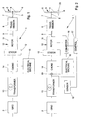
- Fig. 1 is a single line block diagram of a first preferred embodiment example of the new wind power station.
- Fig. 2 is a single line block diagram of a second preferred embodiment example of the new wind power station; and
- Fig. 3 is a block diagram of a third preferred embodiment of the new wind power station in which three separate lines for three electrical phases are depicted.
-
- Referring now in greater detail to the drawings, Fig. 1 illustrates a wind power station 1 connected to a
power grid 2. The wind power station 1 includes awind rotor 3 having at least one, typically 2 or 3blades 4, each of which being connected to arotatable shaft 5. Generally, therotatable shaft 5 is oriented horizontally at a distance to the ground which is in the order of the diameter of thewind rotor 3. Thus, thetips 6 of theblades 4 keep a distance to the ground of about half of the diameter of thewind rotor 3. Therotatable shaft 5 of thewind rotor 3 is mechanically coupled to aninput shaft 7 of atransmission 8. Thetransmission 8 is a fixed ratio transmission increasing the rotational speed of itsinput shaft 7 into a higher output speed of itsoutput shaft 9. In this way the rotational speed of thewind rotor 3 is raised into an operation range of agenerator 10, arotor 11 of which is mechanically coupled to theoutput shaft 9 of the transmission for rotation therewith. Astator 12 of thegenerator 10 is electrically coupled to thepower grid 2. Thegenerator 10 is an asynchronous generator which is provided with an alternating voltage required for its operation by thepower grid 2 and which provides an alternating currant at the same frequency as the alternating voltage to thepower grid 2. Atransformer 13 and achoke 14 are electrically arranged between thepower grid 2 and thestator 12 of thegenerator 10. Thetransformer 13 serves for transforming the height of the voltage at which thegenerator 10 is operated into a height of the voltage at which thepower grid 2 is operating. Thetransformer 13 does neither affect the frequency of the alternating voltage provided to thegenerator 10 by thepower grid 2, nor does it have a considerable effect on the time at which the alternating voltage to be provided by the power grid is present at thegenerator 10 or not. Thechoke 14 and a synchronouselectrical machine 15 which is coupled to thechoke 14 via a branch line together form a protection unit for thegenerator 10 and thetransmission 8 of the wind power station 1. The protection unit protects thegenerator 10 and thetransmission 8 against breakdowns of the alternating voltage provided by thepower grid 2 for the operation of thegenerator 10. Such sudden drops in the operation voltage of thegenerator 10 may cause a torque reversal at therotor 11 and at theoutput shaft 9 of thetransmission 8 resulting into a shock impact on the shafts and gears in thetransmission 8. Such a shock impact may strongly reduces the lifetime of a transmission. In case of a breakdown of thepower grid 2 thechoke 14 which has a high inductance decouples thegenerator 10 from thepower grid 2 so that the breakdown of thepower grid 2 is strongly retarded at thegenerator 10. At the same time the synchronouselectrical machine 15 which is running with a rotational speed corresponding to the frequency of the alternating voltage previously provided by thegrid 2 provides any reactive power which required for the operation of thegenerator 10 and which is normally provided by thepower grid 2. From this state, in which it is not yet noticeable at thegenerator 10 at all that thepower grid 2 broke down, the alternating voltage and its frequency at thegenerator 10 drop slowly. This slow drop does not result in any shock impact on thetransmission 8. The inductance of thechoke 14 should be ...
The synchronouselectrical machine 15 should be connected to thechoke 14 closer to thegenerator 10 then to thepower grid 2. It is preferred, that the partial inductance of thechoke 14 between the connecting point and thegenerator 10 is about one third of the total inductance of thechoke 14. The nominal capacity of the synchronouselectrical machine 15 should be in the order of about 50 % of the nominal capacity of thegenerator 10. It is not necessary to have a synchronouselectrical machine 15 of the same nominal capacity as thegenerator 10. - Referring now to the embodiment example of Fig. 2, the following differences with regard to Fig. 1 are to be noticed. The
generator 10 is an asynchronous double fed generator. At least onepower converter 16 which is electrically coupled to thepower grid 2 on the generator side of thechoke 14 provides electrical quantities to therotor 11 of thegenerator 10. This allows for operating thegenerator 10 with a high efficiency over a great range of rotational speeds of therotor 11, i.e. of thewind rotor 3. With a simple asynchronous generator like that one of Fig. 1 the operation point of thegenerator 10 can only be adapted to the actual output speed of thetransmission 8 by switching between different pole groups, if thegenerator 10 is a multi pole electrical machine. Thepower converter 16 in Fig. 2 is controlled by acontrol unit 17 adapting the point of operation of thegenerator 10 to the present wind conditions. Further, thecontrol unit 17 receives a signal from asensor 18 surveying the alternating voltage as supplied by thepower grid 2. In case of a breakdown of thepower grid 2 thiscontrol unit 17 opens aswitch 19 disconnecting thechoke 14 from thepower grid 2 to avoid that the broken downpower grid 2 further affects the wind power station 1. Opening theswitch 19 takes some time which is covered by the decoupling effects of thechoke 14. Further, upon a breakdown of thepower grid 2 being signaled, thecontrol unit 17 operates thepower converter 16 in an emergency mode to set down the wind power station 1 in a gentle way. Setting down the wind power station 1 may include switching into a no-load operation of thewind rotor 3 or stopping thewind rotor 3 with abreak 20 operated by thecontrol unit 17. Setting down the wind power station 1 may also include removing any excess electrical energy produced by thegenerator 10 which may no longer be supplied to thepower grid 2 by means of a resistor, i.e. by means of converting it into heat. - Now referring to Fig. 3 in which separate lines are depicted for the separate phases of the
power grid 2, it becomes clear, that thechoke 14 comprises onechoke power grid 2. Thepower converter 16 is also divided up into at least threepower converters generator 10 and the synchronouselectrical machine 15 are both three phase electrical machines. It is common nomenclature to speak of rotary current and rotary voltage in the case of three symmetric phases, i.e. in the case of three symmetrically alternating voltages and currents. The additional feature of the embodiment example according Fig. 3 is acos phi sensor 21 surveying a phase angle between the rotary voltage provided by thepower grid 2 and the rotary current provided by thegenerator 10 to thepower grid 2 in the normal operation of the wind power station 1. Any deviation of phi from zero, i.e. of cos phi from 1, results into reactive power to be compensated by thepower grid 2. To avoid this need of compensation thesensor 21 is connected to afurther control unit 22 providing appropriate electrical quantities to the synchronouselectrical machine 15 to use it as a phase shifter for keeping the value of cos phi within a desired range. This means, it is made use of the capability of the synchronouselectrical machine 15 to provide reactive power also in the normal operation of the wind power station 1. Cos phi can be separately surveyed for all three different phases. It may, however, often be sufficient to only survey cos phi for one of the phases as a representative of all three phases. Beside theses details, the wind power station according to Fig. 3 generally operates in the same way as those of Figs. 1 and 2. - Now, typical inductance values of the
choke 14 will be given for a wind power station according to any of the Figs. 1 to 3. The inductance of thechoke 14 has two components: the first component L1 is the inductance of thechoke 14 between its end at the power grid side and the coupling point of theelectrical machine 15 to thechoke 14 which is the so-called power grid side tap of thechoke 14; and the second component L2 is the inductance of the choke between the coupling point of theelectrical machine 15 to thechoke 14 and its end at the generator side which is the so-called generator side tap of thechoke 14. The value of L1 is about 50 % of a nominal reactance of thegenerator 10 under its actual operation conditions. With agenerator 10 having a nominal capacity of 1500 kW, and operating at a voltage of 690 V and at a current frequency of 50 Hz, for example, the nominal reactance is 1.011 mH. Thus, L1 is about 0.505 mH in this example. L2 is to be selected according to L2 = (L")2/L1 based on L1 and a subtransient reactance of theelectrical machine 15. The subtransient reactance L" depends on the actual design of theelectrical machine 15. Typically, it is in a range of 6 to 15 % of the nominal reactance of the electrical machine at its actual operation conditions. When measures are taken to reduce the subtransient reactance L" of theelectrical machine 15 to keep L2 low, while maintaining the nominal capacity of theelectrical machine 15, the production costs of theelectrical machine 15 are increased. In the following examples (a) to (d), a subtransient reactance being 10 % of the nominal reactance of theelectrical machine 15 is assumed, which is a suitable compromise with regard to the production costs. For indicating total values of L2 in mH, it is further assumed that thegenerator 10 is the generator stated above having a nominal capacity of 1500 kW, and operating at a voltage of 690 V and at a current frequency of 50 Hz. - Example (a): If the nominal capacity of the
electrical machine 15 is one third of the nominal capacity of thegenerator 10, i.e. 500 kW, the value of L2 is about 18 % of the nominal reactance of thegenerator 10 under its actual operation conditions, i.e. 0.182 mH. - Example (b): If the nominal capacity of the
electrical machine 15 is one half of the nominal capacity of thegenerator 10, i.e. 750 kW, the value of L2 is about to 8 % of the nominal reactance of thegenerator 10 under its actual operation conditions, i.e. 0.081 mH. - Example (c): If the nominal capacity of the
electrical machine 15 is two thirds of the nominal capacity of thegenerator 10, i.e. 1.000 kW, the value of L2 is about 4,5 % of the nominal reactance of thegenerator 10 under its actual operation conditions, i.e. 0.045 mH. - Example (d): If the nominal capacity of the
electrical machine 15 is equal to the nominal capacity of thegenerator 10, i.e. 1.500 kW, the value of L2 is about 2 % of the nominal reactance of thegenerator 10 under its actual operation conditions, i.e. 0.020 mH. -
- Many variations and modifications may be made to the preferred embodiments of the invention without departing substantially from the spirit and principles of the invention. All such modifications and variations are intended to be included herein within the scope of the present invention, as defined by the following claims.
Claims (12)
- A wind power station comprising:wherein a protection unit protecting the generator and the transmission against accidental breakdowns of the at least one alternating voltage provided by the power grid includes:a wind rotor including at least one blade mounted to a rotatable shaft;a transmission having an input shaft mechanically coupled to the rotatable shaft for rotation therewith at a variable input speed, and an output shaft rotating at a variable output speed which is increased at a fixed ratio as compared to the input speed; andan asynchronous generator having a generator rotor mechanically coupled to the output shaft of the transmission for rotation therewith, and a generator stator electrically coupled to a power grid which provides at least one alternating voltage having a grid frequency to the generator, the generator supplying at least one alternating current to the power grid at the grid frequency;at least one choke electrically arranged between the power grid and the generator stator, anda synchronous electrical machine electrically coupled to the choke.
- The wind power station of claim 1, wherein the generator is an asynchronous double fed generator, the generator being electrically coupled to the power grid via at least one power converter, the at least one power converter being electrically arranged on the same side of the choke as the generator stator.
- The wind power station of claim 1 or 2, wherein a nominal capacity of the electrical machine is between 20 and 100 % of a nominal capacity of the generator.
- The wind power station of any of the claims 1 to 3, wherein a nominal capacity of the electrical machine is between 30 and 80 % of a nominal capacity of the generator.
- The wind power station of any of the claims 1 to 4, wherein a partial inductance of the choke between the power grid and a coupling point of the electrical machine to the choke is about 50 % of a nominal reactance of the asynchronous generator under its actual operation conditions.
- The wind power station of claim 5, wherein a partial inductance of the choke between the coupling point of the electrical machine to the choke and the generator stator is about (L")2/L1, wherein L1 is the partial inductance of the choke between the power grid and the coupling point of the electrical machine to the choke, and wherein L" is a subtransient reactance of the electrical machine.
- The wind power station of any of the claims 1 to 6, wherein the generator is a multiphase generator, one choke being provided for each phase of the generator.
- The wind power station of claim 6, wherein the synchronous electrical machine is a multiphase machine having one phase per phase of the asynchronous generator, each phase being coupled to one of the chokes.
- The wind power station of claim 2, wherein a sensor is provided for surveying the alternating voltage provided by the power grid on the power grid side of the choke, the sensor signaling a breakdown of the voltage to a control unit controlling the at least one power converter.
- The wind power station of claim 1, wherein a sensor is provided for surveying a phase angle between the at least one alternating voltage provided by the power grid and the at least one alternating current supplied by the generator, the sensor signaling the phase angle to a control unit controlling the phase angle within predetermined threshold values by supplying electrical quantities to the electrical machine.
- The wind power station of claim 1, wherein a transformer is electrically arranged between the choke and the power grid.
- A protection unit for a wind power station comprising:wherein the protection unit protects the generator, the power converters and the transmission against accidental breakdowns of the rotary voltage provided by the power grid, and includes:a wind rotor including at least one blade mounted to a rotatable shaft;a transmission having an input shaft mechanically coupled to the rotatable shaft for rotation therewith at a variable input speed, and an output shaft rotating at a variable output speed which is increased at a fixed ratio as compared to the input speed; andan asynchronous double fed three phase generator having a generator rotor mechanically coupled to the output shaft of the transmission for rotation therewith and electrically coupled to a three phase power grid via at least one power converter per phase of the power grid, and a generator stator electrically coupled to a power grid which provides a rotary voltage having a grid frequency to the generator, the generator supplying a rotary current to the power grid at the grid frequency;one choke per phase of the power grid electrically arranged between the power grid on the one hand, and the generator stator and at least one of the power converters of the generator rotor on the other hand, anda three phase synchronous electrical machine electrically coupled to the chokes.
Applications Claiming Priority (2)
| Application Number | Priority Date | Filing Date | Title |
|---|---|---|---|
| US10/830,626 US7038330B2 (en) | 2004-04-23 | 2004-04-23 | Protection for wind power station |
| US830626 | 2004-04-23 |
Publications (2)
| Publication Number | Publication Date |
|---|---|
| EP1589630A2 true EP1589630A2 (en) | 2005-10-26 |
| EP1589630A3 EP1589630A3 (en) | 2009-07-08 |
Family
ID=34935492
Family Applications (1)
| Application Number | Title | Priority Date | Filing Date |
|---|---|---|---|
| EP05008695A Withdrawn EP1589630A3 (en) | 2004-04-23 | 2005-04-21 | Protection for wind power station |
Country Status (2)
| Country | Link |
|---|---|
| US (1) | US7038330B2 (en) |
| EP (1) | EP1589630A3 (en) |
Cited By (5)
| Publication number | Priority date | Publication date | Assignee | Title |
|---|---|---|---|---|
| WO2007107158A1 (en) * | 2006-03-17 | 2007-09-27 | Vestas Wind Systems A/S | Protection system for an electric generator, wind turbine and use hereof |
| CN102646991A (en) * | 2012-04-12 | 2012-08-22 | 山东电力研究院 | Low-voltage ride-through switch and dynamic resistor for double-fed type wind driven generator set |
| CN102723727A (en) * | 2012-04-27 | 2012-10-10 | 江苏吉泰科电气股份有限公司 | Grid connection control method of double-fed wind-driven generator |
| CN104504605A (en) * | 2014-05-08 | 2015-04-08 | 广东电网公司阳江供电局 | Method of risk evaluation of electrical power system containing wind power integration |
| WO2019049102A1 (en) * | 2017-09-11 | 2019-03-14 | Ks Research, Société Anonyme | Protection system for limiting the impact of the disruptions of an external electrical network on the local network of a site connected to the external network |
Families Citing this family (18)
| Publication number | Priority date | Publication date | Assignee | Title |
|---|---|---|---|---|
| JP4168252B2 (en) * | 2002-12-27 | 2008-10-22 | 株式会社安川電機 | Power generation system and control method thereof |
| PT1499009E (en) * | 2003-07-15 | 2008-01-14 | Gamesa Innovation & Tech Sl | Control and protection of a doubly-fed induction generator system |
| DE102004028530B4 (en) * | 2004-06-11 | 2015-05-21 | Alstom Technology Ltd. | Method for operating a power plant |
| US7288921B2 (en) * | 2004-06-25 | 2007-10-30 | Emerson Process Management Power & Water Solutions, Inc. | Method and apparatus for providing economic analysis of power generation and distribution |
| US7215035B2 (en) * | 2005-02-22 | 2007-05-08 | Xantrex Technology, Inc. | Method and apparatus for converting wind generated electricity to constant frequency electricity for a utility grid |
| DK1752660T3 (en) * | 2005-08-12 | 2013-06-17 | Gen Electric | Overvoltage protection device for a wind turbine |
| US7425771B2 (en) * | 2006-03-17 | 2008-09-16 | Ingeteam S.A. | Variable speed wind turbine having an exciter machine and a power converter not connected to the grid |
| CN101401294B (en) * | 2006-03-17 | 2013-04-17 | 英捷电力技术有限公司 | Variable speed wind turbine having an exciter machine and a power converter not connected to the grid |
| DE102006040930A1 (en) * | 2006-08-31 | 2008-03-20 | Nordex Energy Gmbh | Method for operating a wind turbine with a synchronous generator and a superposition gear |
| US7622815B2 (en) * | 2006-12-29 | 2009-11-24 | Ingeteam Energy, S.A. | Low voltage ride through system for a variable speed wind turbine having an exciter machine and a power converter not connected to the grid |
| DE102007008761B4 (en) * | 2007-02-22 | 2010-10-07 | Schuler Pressen Gmbh & Co. Kg | Wind turbine with braced gear |
| DE102007060958A1 (en) * | 2007-12-14 | 2009-06-25 | Repower Systems Ag | Control device for wind turbines with power failure detection |
| US8188610B2 (en) * | 2008-09-08 | 2012-05-29 | General Electric Company | Wind turbine having a main power converter and an auxiliary power converter and a method for the control thereof |
| ES2607118T3 (en) * | 2009-02-27 | 2017-03-29 | Acciona Windpower S.A. | Wind turbine control method to dampen vibrations |
| CN101958683B (en) * | 2010-08-09 | 2012-05-23 | 重庆科凯前卫风电设备有限责任公司 | Method for acquiring redundant stator voltage signal of double-fed wind turbine |
| US8941961B2 (en) | 2013-03-14 | 2015-01-27 | Boulder Wind Power, Inc. | Methods and apparatus for protection in a multi-phase machine |
| CN104836251A (en) * | 2015-04-20 | 2015-08-12 | 沈阳工程学院 | Multifunctional wind turbine power generation system |
| US10075114B2 (en) * | 2016-03-03 | 2018-09-11 | General Electric Company | System and method for controlling DC link voltage of a power converter |
Family Cites Families (12)
| Publication number | Priority date | Publication date | Assignee | Title |
|---|---|---|---|---|
| US4439823A (en) * | 1982-01-11 | 1984-03-27 | Westinghouse Electric Corp. | Converting multiphase power from one frequency to another using current waveforms |
| US4525633A (en) * | 1982-09-28 | 1985-06-25 | Grumman Aerospace Corporation | Wind turbine maximum power tracking device |
| US4994684A (en) * | 1989-01-30 | 1991-02-19 | The State Of Oregon Acting By And Through The State Board Of Higher Education On Behalf Of Oregon State University | Doubly fed generator variable speed generation control system |
| US4992721A (en) * | 1990-01-26 | 1991-02-12 | Sundstrand Corporation | Inverter for starting/generating system |
| US5083039B1 (en) * | 1991-02-01 | 1999-11-16 | Zond Energy Systems Inc | Variable speed wind turbine |
| JP2553319B2 (en) * | 1994-06-17 | 1996-11-13 | 株式会社東芝 | Variable speed generator motor |
| US5798631A (en) * | 1995-10-02 | 1998-08-25 | The State Of Oregon Acting By And Through The State Board Of Higher Education On Behalf Of Oregon State University | Performance optimization controller and control method for doubly-fed machines |
| ATE207668T1 (en) * | 1996-12-20 | 2001-11-15 | Ponte Manuel Dos Santos Da | HYBRID GENERATOR DEVICE |
| AU2001274396A1 (en) * | 2000-05-23 | 2001-12-03 | Vestas Wind Systems A/S | Variable speed wind turbine having a matrix converter |
| US6670721B2 (en) * | 2001-07-10 | 2003-12-30 | Abb Ab | System, method, rotating machine and computer program product for enhancing electric power produced by renewable facilities |
| AU2002341849A1 (en) * | 2001-10-01 | 2003-04-14 | Bruce H. Colley | Induction generator power supply |
| US7015595B2 (en) * | 2002-02-11 | 2006-03-21 | Vestas Wind Systems A/S | Variable speed wind turbine having a passive grid side rectifier with scalar power control and dependent pitch control |
-
2004
- 2004-04-23 US US10/830,626 patent/US7038330B2/en not_active Expired - Fee Related
-
2005
- 2005-04-21 EP EP05008695A patent/EP1589630A3/en not_active Withdrawn
Non-Patent Citations (6)
| Title |
|---|
| A.J. TSITSOVITS, L.L. FRERIS: "Dynamics of an isolated power system supplied from diesel and wind" IEE PROCEEDINGS, vol. 130, no. A, December 1983 (1983-12), pages 587-595, XP002529538 * |
| CARDENAS R ET AL: "Power smoothing in a variable speed wind-diesel system" PESC'03. 2003 IEEE 34TH. ANNUAL POWER ELECTRONICS SPECIALISTS CONFERENCE. CONFERENCE PROCEEDINGS. ACAPULCO, MEXICO, JUNE 15 - 19, 2003; [ANNUAL POWER ELECTRONICS SPECIALISTS CONFERENCE], NEW YORK, NY :; IEEE, US, vol. 2, 15 June 2003 (2003-06-15), pages 754-759, XP010648903 ISBN: 978-0-7803-7754-7 * |
| DARRELMANN H: "Comparison of high power short time flywheel storage systems" TELECOMMUNICATION ENERGY CONFERENCE, 1999. INTELEC '99. THE 21ST INTER NATIONAL COPENHAGEN, DENMARK 6-9 JUNE 1999, PISCATAWAY, NJ, USA,IEEE, US, 6 June 1999 (1999-06-06), page 492pp, XP010351426 ISBN: 978-0-7803-5624-5 * |
| PENA R S ET AL: "Vector controlled induction machines for stand-alone wind energy applications" INDUSTRY APPLICATIONS CONFERENCE, 2000. CONFERENCE RECORD OF THE 2000 IEEE 8-12 OCTOBER 2000, PISCATAWAY, NJ, USA,IEEE, vol. 3, 8 October 2000 (2000-10-08), pages 1409-1415, XP010521302 ISBN: 978-0-7803-6401-1 * |
| RICHARD A EPPERLY ET AL: "Considerations When Applying ASD's in Continuous Processes" IEEE TRANSACTIONS ON INDUSTRY APPLICATIONS, IEEE SERVICE CENTER, PISCATAWAY, NJ, US, vol. 33, no. 2, 1 April 1997 (1997-04-01), XP011022165 ISSN: 0093-9994 * |
| RICHARD T ET AL: "Power quality improvement - case study of the connection of four 1.6 MVA flywheel dynamic UPS systems to a medium voltage distribution network" 2001 IEEE/PES TRANSMISSION AND DISTRIBUTION CONFERENCE AND EXPOSITION. ATLANTA, CA, OCT. 28 - NOV. 2, 2001; [IEEE/PES TRANSMISSION AND DISTRIBUTION CONFERENCE AND EXPOSITION], NEW YORK, NY : IEEE, US, vol. 1, 28 October 2001 (2001-10-28), pages 253-258, XP010568538 ISBN: 978-0-7803-7285-6 * |
Cited By (11)
| Publication number | Priority date | Publication date | Assignee | Title |
|---|---|---|---|---|
| WO2007107158A1 (en) * | 2006-03-17 | 2007-09-27 | Vestas Wind Systems A/S | Protection system for an electric generator, wind turbine and use hereof |
| AU2007229157B2 (en) * | 2006-03-17 | 2010-01-07 | Vestas Wind Systems A/S | Protection system for an electric generator, wind turbine and use hereof |
| US7830031B2 (en) | 2006-03-17 | 2010-11-09 | Vestas Wind Systems A/S | Protection system for an electric generator, wind turbine and use hereof |
| CN102646991A (en) * | 2012-04-12 | 2012-08-22 | 山东电力研究院 | Low-voltage ride-through switch and dynamic resistor for double-fed type wind driven generator set |
| CN102646991B (en) * | 2012-04-12 | 2014-10-15 | 山东电力研究院 | Low-voltage ride-through switch and dynamic resistor for double-fed type wind driven generator set |
| CN102723727A (en) * | 2012-04-27 | 2012-10-10 | 江苏吉泰科电气股份有限公司 | Grid connection control method of double-fed wind-driven generator |
| CN102723727B (en) * | 2012-04-27 | 2014-10-29 | 江苏吉泰科电气股份有限公司 | Grid connection control method of double-fed wind-driven generator |
| CN104504605A (en) * | 2014-05-08 | 2015-04-08 | 广东电网公司阳江供电局 | Method of risk evaluation of electrical power system containing wind power integration |
| WO2019049102A1 (en) * | 2017-09-11 | 2019-03-14 | Ks Research, Société Anonyme | Protection system for limiting the impact of the disruptions of an external electrical network on the local network of a site connected to the external network |
| BE1025533B1 (en) * | 2017-09-11 | 2019-04-08 | KS RESEARCH société anonyme | Protection system to limit the impact of disturbances of an external electrical network on the local network of a site connected to the external network |
| US11594890B2 (en) | 2017-09-11 | 2023-02-28 | Ks Research, Société Anonyme | Protection system for limiting an impact of disruptions of an external electrical network on a local network |
Also Published As
| Publication number | Publication date |
|---|---|
| EP1589630A3 (en) | 2009-07-08 |
| US7038330B2 (en) | 2006-05-02 |
| US20050236838A1 (en) | 2005-10-27 |
Similar Documents
| Publication | Publication Date | Title |
|---|---|---|
| EP1589630A2 (en) | Protection for wind power station | |
| EP0939993B1 (en) | Isolated electrical system including asynchronous machine with prime mover and inverter/rectifier | |
| US7709972B2 (en) | Wind turbine system for satisfying low-voltage ride through requirement | |
| US8084875B2 (en) | Wind energy installation with an extended rotation speed range | |
| US8013461B2 (en) | Power conversion system and method for a rotary power generation system | |
| JP5014437B2 (en) | Low voltage ride-through system for a variable speed wind turbine having an exciter and a power converter not connected to the transmission system | |
| CN101304234B (en) | Power converters | |
| EP2280166A1 (en) | Wind turbine operation method and system | |
| US5406190A (en) | Device for generating electrical energy having an A.C. generator coupled to a turbine | |
| KR101751063B1 (en) | Control of heavy machines | |
| EP1192702B1 (en) | Wind power plant and method for operating it | |
| US4652807A (en) | Starting method for induction motors | |
| EP3599376B1 (en) | Wind turbines and methods | |
| EP1638199A1 (en) | Motor drive system | |
| US20110156390A1 (en) | Method for controlling a wind turbine | |
| KR102590813B1 (en) | Wind power generator and method for operating thereof | |
| JP2001178195A (en) | Generator equipment | |
| AU2015200109B2 (en) | Electric drive shaft and vehicle comprising such an electric drive shaft | |
| EP1104090A2 (en) | Electric generator and method for operating the same | |
| WO2021219610A1 (en) | Wind turbine electrical power generating system | |
| CN111490708A (en) | Double-shaft excitation device of synchronous phase modulator and adjusting method | |
| GB2276022A (en) | Frequency stabilised A.C.power supply system | |
| JP2004222392A (en) | Connection device for counteracting variation in instantaneous voltage | |
| JPH0382339A (en) | Synchronous phase modifying equipment |
Legal Events
| Date | Code | Title | Description |
|---|---|---|---|
| PUAI | Public reference made under article 153(3) epc to a published international application that has entered the european phase |
Free format text: ORIGINAL CODE: 0009012 |
|
| AK | Designated contracting states |
Kind code of ref document: A2 Designated state(s): AT BE BG CH CY CZ DE DK EE ES FI FR GB GR HU IE IS IT LI LT LU MC NL PL PT RO SE SI SK TR |
|
| AX | Request for extension of the european patent |
Extension state: AL BA HR LV MK YU |
|
| PUAL | Search report despatched |
Free format text: ORIGINAL CODE: 0009013 |
|
| AK | Designated contracting states |
Kind code of ref document: A3 Designated state(s): AT BE BG CH CY CZ DE DK EE ES FI FR GB GR HU IE IS IT LI LT LU MC NL PL PT RO SE SI SK TR |
|
| AX | Request for extension of the european patent |
Extension state: AL BA HR LV MK YU |
|
| RAP1 | Party data changed (applicant data changed or rights of an application transferred) |
Owner name: PILLER GROUP GMBH |
|
| 17P | Request for examination filed |
Effective date: 20090826 |
|
| STAA | Information on the status of an ep patent application or granted ep patent |
Free format text: STATUS: THE APPLICATION HAS BEEN WITHDRAWN |
|
| 17Q | First examination report despatched |
Effective date: 20091130 |
|
| 18W | Application withdrawn |
Effective date: 20091110 |