EP1589539A2 - Grid insert for the lowermost grid in a fuel assembly - Google Patents
Grid insert for the lowermost grid in a fuel assembly Download PDFInfo
- Publication number
- EP1589539A2 EP1589539A2 EP05008025A EP05008025A EP1589539A2 EP 1589539 A2 EP1589539 A2 EP 1589539A2 EP 05008025 A EP05008025 A EP 05008025A EP 05008025 A EP05008025 A EP 05008025A EP 1589539 A2 EP1589539 A2 EP 1589539A2
- Authority
- EP
- European Patent Office
- Prior art keywords
- grid
- lowermost
- insert
- straps
- assembly
- Prior art date
- Legal status (The legal status is an assumption and is not a legal conclusion. Google has not performed a legal analysis and makes no representation as to the accuracy of the status listed.)
- Withdrawn
Links
Images



Classifications
-
- G—PHYSICS
- G21—NUCLEAR PHYSICS; NUCLEAR ENGINEERING
- G21C—NUCLEAR REACTORS
- G21C3/00—Reactor fuel elements and their assemblies; Selection of substances for use as reactor fuel elements
- G21C3/30—Assemblies of a number of fuel elements in the form of a rigid unit
- G21C3/32—Bundles of parallel pin-, rod-, or tube-shaped fuel elements
- G21C3/33—Supporting or hanging of elements in the bundle; Means forming part of the bundle for inserting it into, or removing it from, the core; Means for coupling adjacent bundles
- G21C3/332—Supports for spacer grids
-
- F—MECHANICAL ENGINEERING; LIGHTING; HEATING; WEAPONS; BLASTING
- F16—ENGINEERING ELEMENTS AND UNITS; GENERAL MEASURES FOR PRODUCING AND MAINTAINING EFFECTIVE FUNCTIONING OF MACHINES OR INSTALLATIONS; THERMAL INSULATION IN GENERAL
- F16F—SPRINGS; SHOCK-ABSORBERS; MEANS FOR DAMPING VIBRATION
- F16F15/00—Suppression of vibrations in systems; Means or arrangements for avoiding or reducing out-of-balance forces, e.g. due to motion
- F16F15/02—Suppression of vibrations of non-rotating, e.g. reciprocating systems; Suppression of vibrations of rotating systems by use of members not moving with the rotating systems
- F16F15/04—Suppression of vibrations of non-rotating, e.g. reciprocating systems; Suppression of vibrations of rotating systems by use of members not moving with the rotating systems using elastic means
- F16F15/06—Suppression of vibrations of non-rotating, e.g. reciprocating systems; Suppression of vibrations of rotating systems by use of members not moving with the rotating systems using elastic means with metal springs
- F16F15/067—Suppression of vibrations of non-rotating, e.g. reciprocating systems; Suppression of vibrations of rotating systems by use of members not moving with the rotating systems using elastic means with metal springs using only wound springs
-
- F—MECHANICAL ENGINEERING; LIGHTING; HEATING; WEAPONS; BLASTING
- F16—ENGINEERING ELEMENTS AND UNITS; GENERAL MEASURES FOR PRODUCING AND MAINTAINING EFFECTIVE FUNCTIONING OF MACHINES OR INSTALLATIONS; THERMAL INSULATION IN GENERAL
- F16F—SPRINGS; SHOCK-ABSORBERS; MEANS FOR DAMPING VIBRATION
- F16F1/00—Springs
- F16F1/02—Springs made of steel or other material having low internal friction; Wound, torsion, leaf, cup, ring or the like springs, the material of the spring not being relevant
- F16F1/04—Wound springs
- F16F1/12—Attachments or mountings
-
- G—PHYSICS
- G21—NUCLEAR PHYSICS; NUCLEAR ENGINEERING
- G21C—NUCLEAR REACTORS
- G21C3/00—Reactor fuel elements and their assemblies; Selection of substances for use as reactor fuel elements
- G21C3/30—Assemblies of a number of fuel elements in the form of a rigid unit
- G21C3/32—Bundles of parallel pin-, rod-, or tube-shaped fuel elements
- G21C3/334—Assembling, maintenance or repair of the bundles
-
- Y—GENERAL TAGGING OF NEW TECHNOLOGICAL DEVELOPMENTS; GENERAL TAGGING OF CROSS-SECTIONAL TECHNOLOGIES SPANNING OVER SEVERAL SECTIONS OF THE IPC; TECHNICAL SUBJECTS COVERED BY FORMER USPC CROSS-REFERENCE ART COLLECTIONS [XRACs] AND DIGESTS
- Y02—TECHNOLOGIES OR APPLICATIONS FOR MITIGATION OR ADAPTATION AGAINST CLIMATE CHANGE
- Y02E—REDUCTION OF GREENHOUSE GAS [GHG] EMISSIONS, RELATED TO ENERGY GENERATION, TRANSMISSION OR DISTRIBUTION
- Y02E30/00—Energy generation of nuclear origin
- Y02E30/30—Nuclear fission reactors
Definitions
- the present invention relates to grid assemblies for fuel assemblies within a nuclear power plant. More specifically, the invention provides a lowermost grid assembly having a grid insert secured therein for removably securing the lowermost grid between the guide tubes and lower nozzle of the fuel assembly.
- a typical fuel assembly for a nuclear reactor has a plurality of fuel rods held in place by a plurality of grids.
- the grids are distributed along the length of the fuel assembly, and are held in place by guide tubes extending lengthwise through the fuel assembly.
- the guide tubes are structured to receive devices such as control rods or instrumentation.
- the top and bottom of the fuel assembly each include a nozzle.
- a typical grid includes a first plurality of grid straps substantially parallel to each other, and a second plurality of grid straps substantially parallel to each other and substantially perpendicular to the first grid straps.
- a perimeter strap surrounds the grid.
- a plurality of substantially square cells are thereby defined within each grid.
- Each cell includes one or more springs and one or more dimples which engage the fuel rod, thereby holding it in place within the cell.
- the grid assembly may also include mixing vanes for the coolant which flows from the bottom to the top of the fuel assembly.
- the lowermost grid assembly further includes debris-trapping features.
- the lowermost grid assembly within the fuel assembly is typically secured to the lower nozzle by a continuous perimeter weld of the perimeter strap of the grid to the lower nozzle.
- this method of attachment of the lower nozzle requires that fuel rods be installed after completion of the welding, because there is no access to the fuel rods from the bottom of the fuel assembly once the lower nozzle is in place. Therefore, the fuel rods must be inserted into the fuel assembly by pushing them through the top of the fuel assembly, instead of the preferred method of pulling the fuel rods through from the bottom of the fuel assembly.
- the present invention provides a lowermost grid for a fuel assembly having a grid insert secured therein.
- the grid insert is structured so that a guide tube may be mechanically secured therein, with a lower nozzle secured to the lower grid assembly and guide tube.
- the grid assembly includes a first and second plurality of metal straps, with the first plurality arranged substantially parallel to each other, and the second plurality arranged substantially parallel to each other and substantially perpendicular to the first plurality of metal straps, thereby forming an egg crate pattern of substantially square cells within the grid assembly.
- Each of the first and second plurality of metal straps have spring and/or dimple elements projecting therefrom into the cells reserved for fuel rods within the matrix, so that a fuel rod may be secured within each of these cells.
- a plurality of larger cells are provided within the matrix for receiving the guide tubes and an instrument tube.
- the grid insert comprises a tube having a retention lip projecting inwardly from its lower end.
- the grid insert is dimensioned and configured to receive a guide tube therein, with the end of the guide tube abutting the grid insert retention lip.
- the guide tube itself includes a fashioned lower end for receiving a mechanical fastener therethrough. Fashioned is defined herein as being dimensioned and configured to mate with a mechanical fastener in a secure fashion.
- An example of a fashioned lower end includes one having a threaded bore for receiving a bolt or screw, or having an end fitting that is so threaded.
- the lower nozzle includes an opening corresponding to each of the grid inserts, with one preferred embodiment including an opening corresponding to each corner, and a fifth opening in the center.
- a mechanical fastener such as a bolt or screw may be passed through the opening, being threadedly secured to the end of the guide tube, and may possibly have a locking disk placed over the screw slot.
- the prior art step of continuous perimeter welding the perimeter strap to the nozzle is avoided. Additionally, the prior continuous perimeter weld required fuel rods to be pushed through the top of the fuel assembly, rather than pulling the fuel rods from the bottom. Once the lower nozzle is welded in place, there is no access to the fuel rods from the bottom of the fuel assembly.
- the present invention therefore provides a precise, secure alignment of the lowermost grid to the lower nozzle.
- the invention further provides a grid insert structured to facilitate securing the grid assembly and lower nozzle together by sandwiching the retention lip of the grid insert between the guide tube end fitting and the lower nozzle when the guide tube is bolted or screwed into place.
- the invention provides a method of securing the lowermost grid assembly to the lower nozzle that is less expensive, less time-consuming, and simpler than previous methods.
- the present invention additionally provides a method of assembling a fuel assembly that permits rods to be pulled from the bottom.
- It is another object of the present invention provide a method of assembling a fuel assembly that permits fuel rods to be installed by pulling them from the bottom instead of pushing them in from the top.
- the present invention provides a lowermost grid for a fuel cell having a grid insert to facilitate securing the lowermost grid to the fuel assembly's lower nozzle.
- the support means 10 for the fuel rods within a fuel assembly are illustrated.
- the support means 10 include a plurality of grid assemblies, for example, the grid assemblies 12-32 in Figure 1. Intermediate grid assemblies 12-32 are secured in place relative to each other by the guide tubes 34, 36, 38. Though only three guide tubes are visible in Figure 1, it will be understood by those skilled in the art that a fourth guide tube is located directly behind guide tube 34, and a fifth guide tube is located directly behind the guide tube 38. It will also be understood by those skilled in the art that a number of guide tubes other than five may be selected, depending on the design of the reactor.
- the guide tubes 38 are structured to permit the insertion of control rods, instrumentation, or other devices therein.
- the bottom of the fuel assembly includes a lowermost grid 40, and a lower nozzle 42 secured directly below the lowermost grid 40.
- the lowermost grid assembly 40 includes a first plurality of metal straps 44, with each of the metal straps 44 being substantially parallel to each other, and a second plurality of metal straps 46, with each of the plurality of metal straps 46 being substantially parallel to each other.
- the intersecting metal straps 44, 46 are interleaved in an egg-crate pattern to form a matrix of substantially square cells 48.
- the lowermost grid 40 may also include a perimeter strap 50.
- Each of the straps 44, 46, 50 includes spring elements 52 and dimples 53 protruding into each of the cells 48 adjacent to and defined by that particular strap 44, 46, 50.
- a plurality of larger cells 56,57 are also defined within the lowermost grid 40, with the illustrated example including one cell 56 corresponding to each corner, and one central cell 57.
- Each of the larger cells 56 is dimensioned and configured to receive a guide tube 34, 36, 38.
- the cells 56 corresponding to the corners of the fuel assembly 40 each include a grid insert 58.
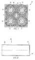
- the grid insert 58 is illustrated.
- the grid insert 58 is tubular, having a top end 60 and lower end 62.
- the lower end 62 includes a retention lip 64 depending inwardly about the periphery of the lower end 62.
- the grid insert 58 may be formed by a punch press, with the die forming the tubing and rolling the bottom lip of the tube to form the retention lip 64.
- the grid inserts 58 are secured within the cells 56, such as by welding, and more preferably by four intersection welds either at the bottom and/or the top of the grid insert where it mates with the grid strap, with each intersection weld being formed between the grid insert and one of the four grid straps 44,46 forming the cell 56.
- the lower nozzle 42 includes a top surface 66 and a bottom surface 68.
- the nozzle 42 defines a plurality of guide tube securing apertures 70 therein, corresponding to the cells 56, and a central aperture 71, corresponding to the cell 57.
- Each of the apertures 70 is surrounded by a downwardly depending hollow cylinder 72.
- the central aperture 71 is counterbored, with a smaller diameter top portion 74, and a larger diameter lower portion 76.
- the lower nozzle 42 also includes a plurality of apertures 78 structured to permit coolant flow therethrough.
- the lower nozzle 42 further defines a perimeter wall 80 depending downward from the bottom surface 68.
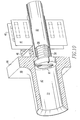
- FIG. 9-10 the method of securing the lowermost grid assembly 40 to the lower nozzle 42 is illustrated.
- the grid insert 58 is secured within the cells 56 of the lowermost grid 40.
- the guide tube 82 having end fitting 84 is inserted into the grid insert 58 until the end fitting 84 abuts the retention lip 64.
- a mechanical fastener such as the screw 86 is inserted through the aperture 70 in the lower nozzle 42 and into the threaded bore 88 to be threadedly secured therein, thereby sandwiching the retention lip 64 between the end fitting 84 and lower nozzle 42.
- a locking disk 90 may then be installed below the screw 86, and welded in place.
- a bolt or screw is illustrated to mechanically secure the retention lip 64 between the guide tube 82 and lower nozzle 42, other mechanical fasteners could be employed for the purpose.
Landscapes
- Engineering & Computer Science (AREA)
- Physics & Mathematics (AREA)
- General Engineering & Computer Science (AREA)
- Plasma & Fusion (AREA)
- High Energy & Nuclear Physics (AREA)
- Mechanical Engineering (AREA)
- Acoustics & Sound (AREA)
- Aviation & Aerospace Engineering (AREA)
- Fuel Cell (AREA)
- Monitoring And Testing Of Nuclear Reactors (AREA)
Abstract
Description
Claims (11)
- A lowermost grid for a fuel assembly, the fuel assembly having a plurality of fuel rods held in place by a plurality of grid assemblies including the lowermost grid assembly and by a plurality of guide tubes, the guide tubes having fashioned lower ends for receiving a mechanical fastener therethrough, the lowermost grid comprising:a first plurality of grid straps arranged substantially parallel to each other;a second plurality of grid straps arranged substantially parallel to each other and substantially perpendicular to the first plurality of grid straps, said first and second plurality of grid straps intersecting each other to form a matrix of substantially square-shaped cells;a perimeter grid strap; andmeans for mechanically securing the grid assembly to a lower nozzle of a fuel cell, the means being structured to be sandwiched between a guide tube and the lower nozzle.
- The lowermost grid according to claim 1, wherein the means for securing the grid assembly to a lower nozzle of a fuel cell comprises a grid insert secured within at least one of the cells, the grid insert being tube-shaped and having an upper end and lower end, the lower end having an internally projecting retention lip disposed thereon, the grid insert being structured to receive a guide tube secured therethrough by a mechanical fastener passing into the bottom end and secured to the guide tube, the retention lip being structured to permit passage of the mechanical fastener but not the guide tube therethrough, whereby the retention lip is held between the guide tube and lower nozzle.
- The lowermost grid according to claim 2, wherein the grid insert is secured within the cell by welding.
- The lowermost grid according to claim 3, wherein the grid insert is secured within the cell by an intersection weld with each of the four grid straps forming the cell.
- The lowermost grid according to claim 1, wherein:the fashioned lower ends of the guide tubes are threaded; andthe mechanical fastener is selected from the group consisting of a bolt and a screw.
- A method of assembling a fuel assembly, the method comprising:providing a first plurality of grid straps arranged substantially parallel to each other;providing a second plurality of grid straps arranged substantially parallel to each other and substantially perpendicular to the first plurality of grid straps, said first and second plurality of grid straps intersecting each other to form a matrix of substantially square-shaped cells;providing a perimeter grid strap; andproviding a grid insert secured within at least one of the cells, the grid insert being tube-shaped and having an upper end and lower end, the lower end having an internally projecting retention lip disposed thereon, the grid insert being structured to receive a guide tube secured therethrough by a mechanical fastener passing into the bottom end and secured to the guide tube.
- The method according to claim 6, wherein the grid insert is secured within the cell by welding.
- The method according to claim 7, wherein the grid insert is welded within the cell by an intersection weld with each of the four grid straps forming the cell.
- The method according to claim 6, further comprising:providing a plurality of intermediate grid assemblies, each intermediate grid assembly having a first plurality of grid straps arranged substantially parallel to each other, and a second plurality of grid straps arranged substantially parallel to each other and substantially perpendicular to the first plurality of grid straps, said first and second plurality of grid straps intersecting each other to form a matrix of substantially square-shaped cells;providing a guide tube secured within each grid insert by a mechanical fastener passing into the bottom end and secured to the guide tube; andinstalling a plurality of fuel rods within the cells of the lowermost grid and the intermediate grids by pulling the fuel rods through from the bottom of the fuel assembly.
- The method according to claim 6, further comprising:providing internal threads within a lower end of the guide tubes; andwherein the mechanical fastener is a bolt or screw.
- A fuel assembly, comprising:a plurality of guide tubes having fashioned lower ends;a lowermost grid assembly, having
a first plurality of grid straps arranged substantially parallel to each other;
a second plurality of grid straps arranged substantially parallel to each other and substantially perpendicular to the first plurality of grid straps, said first and second plurality of grid straps intersecting each other to form a matrix of substantially square-shaped cells;
a perimeter grid strap; and
means for securing the grid assembly to a lower nozzle of a fuel cell, the means being structured to be sandwiched between one of the guide tubes and the lower nozzle; anda plurality of intermediate grid assemblies, each intermediate grid assembly having:a first plurality of grid straps arranged substantially parallel to each other; anda second plurality of grid straps arranged substantially parallel to each other and substantially perpendicular to the first plurality of grid straps, said first and second plurality of grid straps intersecting each other to form a matrix of substantially square-shaped cells, anda plurality of fuel rods held in place by the lowermost grid assembly and the intermediate grid assemblies.
Applications Claiming Priority (2)
| Application Number | Priority Date | Filing Date | Title |
|---|---|---|---|
| US828979 | 1997-03-31 | ||
| US10/828,979 US20050238131A1 (en) | 2004-04-21 | 2004-04-21 | Grid insert for the lowermost grid in a fuel assembly |
Publications (2)
| Publication Number | Publication Date |
|---|---|
| EP1589539A2 true EP1589539A2 (en) | 2005-10-26 |
| EP1589539A3 EP1589539A3 (en) | 2008-03-19 |
Family
ID=34935076
Family Applications (1)
| Application Number | Title | Priority Date | Filing Date |
|---|---|---|---|
| EP05008025A Withdrawn EP1589539A3 (en) | 2004-04-21 | 2005-04-13 | Grid insert for the lowermost grid in a fuel assembly |
Country Status (4)
| Country | Link |
|---|---|
| US (1) | US20050238131A1 (en) |
| EP (1) | EP1589539A3 (en) |
| JP (1) | JP2005308750A (en) |
| KR (1) | KR100758446B1 (en) |
Cited By (3)
| Publication number | Priority date | Publication date | Assignee | Title |
|---|---|---|---|---|
| WO2007012380A1 (en) * | 2005-07-26 | 2007-02-01 | Areva Np Gmbh | Fuel element for a pressurized water nuclear reactor |
| CN101303905B (en) * | 2008-05-14 | 2012-04-25 | 中科华核电技术研究院有限公司 | Fuel assembly and nuclear reactor core using same |
| RU2566674C1 (en) * | 2014-08-05 | 2015-10-27 | Публичное акционерное общество "Машиностроительный завод" (ПАО "МСЗ") | Fuel assembly of nuclear reactor |
Families Citing this family (9)
| Publication number | Priority date | Publication date | Assignee | Title |
|---|---|---|---|---|
| US9620249B2 (en) * | 2007-08-31 | 2017-04-11 | Global Nuclear Fuel—Americas, LLC | Debris shield upper tie plate for nuclear fuel assembly and method to shield assembly from debris |
| AU2007363064B2 (en) | 2007-12-26 | 2014-02-13 | Thorium Power Inc. | Nuclear reactor (variants), fuel assembly consisting of driver-breeding modules for a nuclear reactor (variants) and a fuel cell for a fuel assembly |
| US8116423B2 (en) | 2007-12-26 | 2012-02-14 | Thorium Power, Inc. | Nuclear reactor (alternatives), fuel assembly of seed-blanket subassemblies for nuclear reactor (alternatives), and fuel element for fuel assembly |
| JP5755568B2 (en) | 2008-12-25 | 2015-07-29 | トリウム・パワー、インクThorium Power,Inc. | Light water reactor nuclear fuel assembly and light water reactor |
| US9053826B2 (en) * | 2010-03-03 | 2015-06-09 | Westinghouse Electric Company Llc | Protective grid attachment |
| US10170207B2 (en) | 2013-05-10 | 2019-01-01 | Thorium Power, Inc. | Fuel assembly |
| WO2011143172A1 (en) | 2010-05-11 | 2011-11-17 | Thorium Power, Inc. | Fuel assembly with metal fuel alloy kernel and method of manufacturing thereof |
| US10192644B2 (en) | 2010-05-11 | 2019-01-29 | Lightbridge Corporation | Fuel assembly |
| RU2715387C1 (en) * | 2019-05-27 | 2020-02-27 | федеральное государственное бюджетное образовательное учреждение высшего образования "Нижегородский государственный технический университет им. Р.Е. Алексеева" (НГТУ) | Separation and mixing grid of nuclear reactor fuel assembly |
Family Cites Families (26)
| Publication number | Priority date | Publication date | Assignee | Title |
|---|---|---|---|---|
| US3791466A (en) * | 1969-05-19 | 1974-02-12 | Westinghouse Electric Corp | Low parasitic capture fuel assembly structure |
| DE2350700C3 (en) * | 1973-10-09 | 1978-06-08 | Kraftwerk Union Ag, 4330 Muelheim | Fuel assembly skeleton |
| FR2465295A1 (en) * | 1979-09-06 | 1981-03-20 | Commissariat Energie Atomique | ANTI-ENVOL DEVICE FOR NUCLEAR REACTOR COMBUSTIBLE ELEMENT |
| US4323428A (en) * | 1979-11-07 | 1982-04-06 | Westinghouse Electric Corp. | Reconstitutable fuel assembly for a nuclear reactor |
| FR2514188B1 (en) * | 1981-10-05 | 1985-08-16 | Framatome Sa | FUEL ASSEMBLY FOR A NUCLEAR REACTOR |
| US4576786A (en) * | 1983-12-21 | 1986-03-18 | Westinghouse Electric Corp. | Partial grid for a nuclear reactor fuel assembly |
| US4692302A (en) * | 1983-12-30 | 1987-09-08 | Westinghouse Electric Corp. | Coolant flow mixer grid for a nuclear reactor fuel assembly |
| US4659542A (en) * | 1984-10-03 | 1987-04-21 | Westinghouse Electric Corp. | Grid structure for nuclear fuel assembly |
| US4709909A (en) * | 1985-12-17 | 1987-12-01 | Westinghouse Electric Corp. | Retention strap in a grid assembly fixture |
| US4980121A (en) * | 1989-07-28 | 1990-12-25 | Westinghouse Electric Corp. | Protective device for lower end portion of a nuclear fuel rod cladding |
| JPH03115896A (en) * | 1990-04-20 | 1991-05-16 | Niigata Eng Co Ltd | Processing method for solidification of radioactive waste |
| JP3115300B2 (en) * | 1990-05-21 | 2000-12-04 | 富士電機株式会社 | Load current detection method in power converter |
| US5068083A (en) * | 1990-05-29 | 1991-11-26 | Westinghouse Electric Corp. | Dashpot construction for a nuclear reactor rod guide thimble |
| SE468264B (en) * | 1991-04-11 | 1992-11-30 | Asea Atom Ab | BRAINSLEPATRON FOR A NUCLEAR REACTOR |
| US5303276A (en) * | 1992-10-29 | 1994-04-12 | Westinghouse Electric Corp. | Fuel assembly including deflector vanes for deflecting a component of a fluid stream flowing past such fuel assembly |
| JP3414435B2 (en) * | 1993-04-20 | 2003-06-09 | 三菱原子燃料株式会社 | How to attach the upper nozzle of the fuel assembly |
| US5434898A (en) * | 1994-03-14 | 1995-07-18 | Siemens Power Corporation | Nuclear fuel assembly |
| US5444748A (en) * | 1994-04-04 | 1995-08-22 | Westinghouse Electric Corporation | Grid structure for supporting fuel rods in a nuclear reactor |
| JP3568637B2 (en) * | 1995-07-13 | 2004-09-22 | 三菱原子燃料株式会社 | Method of manufacturing insert for fuel assembly |
| SE506819C2 (en) * | 1996-06-20 | 1998-02-16 | Asea Atom Ab | Fuel cartridge with top and bottom plate which includes side supports for supporting fuel rods. Fuel cartridge where the top and bottom plate includes mixing fins. Fuel cartridge where the top and bottom plate has a wavy cross section |
| FR2750529B1 (en) * | 1996-06-28 | 1998-09-04 | Framatome Sa | GUIDE TUBE FOR NUCLEAR FUEL ASSEMBLY |
| JPH10142366A (en) * | 1996-11-11 | 1998-05-29 | Mitsubishi Heavy Ind Ltd | Fixing structure of lower nozzle of nuclear fuel assembly |
| US6526116B1 (en) * | 1997-07-02 | 2003-02-25 | Westinghouse Electric Company Llc | Nuclear fuel assembly with hydraulically balanced mixing vanes |
| SE521687C2 (en) * | 1998-09-18 | 2003-11-25 | Westinghouse Atom Ab | Sprayer and fuel cartridge for a nuclear boiler water reactor |
| KR100415149B1 (en) * | 2001-03-21 | 2004-01-14 | 한국전력공사 | Double strip mixing grid for a nuclear fuel assembly |
| US6606369B1 (en) * | 2002-03-06 | 2003-08-12 | Westinghouse Electric Company Llc | Nuclear reactor with improved grid |
-
2004
- 2004-04-21 US US10/828,979 patent/US20050238131A1/en not_active Abandoned
-
2005
- 2005-04-13 EP EP05008025A patent/EP1589539A3/en not_active Withdrawn
- 2005-04-15 KR KR1020050031402A patent/KR100758446B1/en not_active Expired - Lifetime
- 2005-04-21 JP JP2005123490A patent/JP2005308750A/en active Pending
Cited By (6)
| Publication number | Priority date | Publication date | Assignee | Title |
|---|---|---|---|---|
| WO2007012380A1 (en) * | 2005-07-26 | 2007-02-01 | Areva Np Gmbh | Fuel element for a pressurized water nuclear reactor |
| CN101228591B (en) * | 2005-07-26 | 2012-04-25 | 阿利发Np有限公司 | Fuel assembly for a pressurized water reactor |
| US9390817B2 (en) | 2005-07-26 | 2016-07-12 | Areva Gmbh | Fuel assembly for a pressurized water reactor |
| CN101303905B (en) * | 2008-05-14 | 2012-04-25 | 中科华核电技术研究院有限公司 | Fuel assembly and nuclear reactor core using same |
| RU2566674C1 (en) * | 2014-08-05 | 2015-10-27 | Публичное акционерное общество "Машиностроительный завод" (ПАО "МСЗ") | Fuel assembly of nuclear reactor |
| WO2016022043A1 (en) * | 2014-08-05 | 2016-02-11 | Публичное акционерное общество "Машиностроительный завод" | Nuclear reactor fuel assembly |
Also Published As
| Publication number | Publication date |
|---|---|
| EP1589539A3 (en) | 2008-03-19 |
| KR20060045760A (en) | 2006-05-17 |
| KR100758446B1 (en) | 2007-09-14 |
| JP2005308750A (en) | 2005-11-04 |
| US20050238131A1 (en) | 2005-10-27 |
Similar Documents
| Publication | Publication Date | Title |
|---|---|---|
| US20050238131A1 (en) | Grid insert for the lowermost grid in a fuel assembly | |
| US7668284B2 (en) | Tube-in-tube threaded dashpot end plug | |
| US4795608A (en) | Nuclear fuel assembly | |
| US5289514A (en) | Fuel assembly for a boiling water reactor with a sealing spring between the foot part and the fuel assembly channel | |
| US20070133734A1 (en) | Rod assembly for nuclear reactors | |
| DE3641974A1 (en) | CORE REACTOR FUEL AND FASTENING DEVICE FOR A LARGE COOLANT PIPE | |
| DE3325749A1 (en) | SPACER FOR A CORE FUEL UNIT | |
| US4716015A (en) | Modular nuclear fuel assembly design | |
| US4203038A (en) | High density spent fuel storage rack | |
| DE69301325T2 (en) | Low pressure loss spacers for nuclear fuel assemblies | |
| US20070183556A1 (en) | Terminal end-piece for a fuel assembly having an arrangement for maintaining the ends of the rods and corresponding assembly | |
| US8576972B2 (en) | Radioisotope production structures, fuel assemblies having the same, and methods of using the same | |
| US9202598B2 (en) | Fail-free fuel bundle assembly | |
| KR940003705B1 (en) | Universal fuel assembly construction for a nuclear reactor | |
| US6118838A (en) | Frame-held neutron-absorbing fuel rod assembly storage rack | |
| US20130272479A1 (en) | Lower end fitting for nuclear fuel assembly made from intersecting metal strips | |
| EP0458202B1 (en) | Fuel assembly for a nuclear reactor | |
| US4522782A (en) | Fuel assembly for a nuclear reactor | |
| US4738820A (en) | Nuclear fuel assembly bottom nozzle attachment system allowing reconstitution | |
| US20030007590A1 (en) | Fastened spacer for grid of a nuclear reactor with associated method | |
| DE2839211C2 (en) | ||
| DE1464284A1 (en) | Nuclear reactor | |
| JPS60111989A (en) | Fuel assembly for nuclear reactor | |
| SK279650B6 (en) | DIVERSIBLE NUCLEAR FUEL ARTICLE | |
| DE29520871U1 (en) | Fuel assembly with a modular structure for a nuclear reactor |
Legal Events
| Date | Code | Title | Description |
|---|---|---|---|
| PUAI | Public reference made under article 153(3) epc to a published international application that has entered the european phase |
Free format text: ORIGINAL CODE: 0009012 |
|
| AK | Designated contracting states |
Kind code of ref document: A2 Designated state(s): AT BE BG CH CY CZ DE DK EE ES FI FR GB GR HU IE IS IT LI LT LU MC NL PL PT RO SE SI SK TR |
|
| AX | Request for extension of the european patent |
Extension state: AL BA HR LV MK YU |
|
| PUAL | Search report despatched |
Free format text: ORIGINAL CODE: 0009013 |
|
| AK | Designated contracting states |
Kind code of ref document: A3 Designated state(s): AT BE BG CH CY CZ DE DK EE ES FI FR GB GR HU IE IS IT LI LT LU MC NL PL PT RO SE SI SK TR |
|
| AX | Request for extension of the european patent |
Extension state: AL BA HR LV MK YU |
|
| RIC1 | Information provided on ipc code assigned before grant |
Ipc: G21C 3/334 20060101ALI20080213BHEP Ipc: G21C 3/332 20060101AFI20050621BHEP |
|
| 17P | Request for examination filed |
Effective date: 20080514 |
|
| AKX | Designation fees paid |
Designated state(s): DE ES FR SE |
|
| 17Q | First examination report despatched |
Effective date: 20090703 |
|
| STAA | Information on the status of an ep patent application or granted ep patent |
Free format text: STATUS: THE APPLICATION IS DEEMED TO BE WITHDRAWN |
|
| 18D | Application deemed to be withdrawn |
Effective date: 20100114 |