EP1589338A2 - Method of reducing the damage on heating installations and liquid, low-sulphur fuel - Google Patents
Method of reducing the damage on heating installations and liquid, low-sulphur fuel Download PDFInfo
- Publication number
- EP1589338A2 EP1589338A2 EP05013646A EP05013646A EP1589338A2 EP 1589338 A2 EP1589338 A2 EP 1589338A2 EP 05013646 A EP05013646 A EP 05013646A EP 05013646 A EP05013646 A EP 05013646A EP 1589338 A2 EP1589338 A2 EP 1589338A2
- Authority
- EP
- European Patent Office
- Prior art keywords
- fuel
- oil
- sulfur
- heating
- combustion
- Prior art date
- Legal status (The legal status is an assumption and is not a legal conclusion. Google has not performed a legal analysis and makes no representation as to the accuracy of the status listed.)
- Pending
Links
Images


Classifications
-
- G—PHYSICS
- G01—MEASURING; TESTING
- G01N—INVESTIGATING OR ANALYSING MATERIALS BY DETERMINING THEIR CHEMICAL OR PHYSICAL PROPERTIES
- G01N33/00—Investigating or analysing materials by specific methods not covered by groups G01N1/00 - G01N31/00
- G01N33/26—Oils; viscous liquids; paints; inks
- G01N33/28—Oils, i.e. hydrocarbon liquids
- G01N33/2817—Oils, i.e. hydrocarbon liquids using a test engine
-
- G—PHYSICS
- G01—MEASURING; TESTING
- G01N—INVESTIGATING OR ANALYSING MATERIALS BY DETERMINING THEIR CHEMICAL OR PHYSICAL PROPERTIES
- G01N17/00—Investigating resistance of materials to the weather, to corrosion, or to light
-
- G—PHYSICS
- G01—MEASURING; TESTING
- G01N—INVESTIGATING OR ANALYSING MATERIALS BY DETERMINING THEIR CHEMICAL OR PHYSICAL PROPERTIES
- G01N31/00—Investigating or analysing non-biological materials by the use of the chemical methods specified in the subgroup; Apparatus specially adapted for such methods
- G01N31/12—Investigating or analysing non-biological materials by the use of the chemical methods specified in the subgroup; Apparatus specially adapted for such methods using combustion
Definitions
- low-sulfur heating oils have come on the market, the one Having a sulfur content of 0.05 to 0.001%.
- Such low-sulfur heating oils occur previously unknown damage to the Metal parts in the boiler room and the oil burner, especially on the flame cup on.
- the damage also occurs in condensing heating systems, which the Use condensation heat and with low-temperature burners, so-called fan blue burners are equipped.
- the damage pictures show sharply outlined, crater-shaped eroded areas with a finely grained surface and distinguish distinct from high-temperature corrosion. Such damage can within a few weeks of start-up of the heating system arise.
- the choice of more corrosion-resistant materials has only limited Influence on the damage pictures.
- the liquid, low-sulfur fuel e.g. batch through a neutral body or in the refinery, to its potential erosive To test the effect of burning in heating systems.
- To examine the Fuel will advantageously be the fuel in combustion air near one Test area fogged and the fuel mist an electric field of tension exposed and inflamed.
- Temperature range is necessary. This temperature range is safe between 350 and 600 ° C. A limited temperature range is between 370 and 550 ° C. In this temperature range, the processes occur, the damage pattern cause. Due to further investigations this temperature range is possibly even more precise restrictable. It could be further observed that the damage patterns accelerate in places that occur due to the fuel be wetted.
- the one has suitable temperature for starting.
- Once the combustion process heat developed, is advantageously converted to cooled fuel oil.
- the cooled fuel oil may advantageously be mixed with a flow improver to keep it as cool as possible, e.g. can be used at minus 10 ° C. Thanks to a cooled fuel will wetted the test area as long as possible.
- the above sequence can be advantageously supplemented with a further process step in which existing test areas are cooled.
- To cool down Turning off the fuel supply is advantageously used air.
- a metal test surface used. This is expediently from a suitable for burner construction Material, eg. B. Alloy 601 manufactured.
- the test surface is advantageously in a burner, e.g. used in an evaporator.
- the test surface may be the inner surface of a Flammbechers be. It can also be the surface of an evaporator. she can in particular also be a surface of a conventional burner.
- the ignition is advantageously carried out by a spark.
- the electrodes can be supplied with an AC voltage, or a constant potential difference exhibit.
- the stress field can be built up between two electrodes, while the test area is grounded. It can also be between an electrode and the Test surface are constructed so that the test surface forms an electrode.
- These the Test surface forming electrode is advantageously made of flat material.
- an oil supply is done according to regulations only after one Pre-ignition time of 10 to 15 seconds. This can in the inventive Test methods are handled as well. It is essential that the plasma one are exposed to electrical stress. Preferably, the stress field already built up during the emergence of the flame.
- the electrodes or the electrode is advantageous in a distance of less than 50 mm, advantageously at a distance of less than 15 mm, or even at a distance of 3 to 7 mm from the metal test surface, or the location of the test area near which the ionization of the fuel occurs.
- the Voltage and the distance between the voltage potentials are each other Accordingly, reciprocally to choose such that the largest possible volume of the Plasma is exposed to the highest possible voltage.
- the plasma advantageously becomes a voltage of 2 times 7500 V and more, preferably at least 2 times 10'000 V, especially preferably exposed to at least 2 times 15,000 volts. It could be determined, however be that individual fuels already at voltages of 200 V or 230 V. Cause damage.
- the test method an advantageous in Flame area arranged metal surface sprayed with the fuel oil or even wetted. So that the ionization of the fuel as long as possible near the test area occurs, the Flammbecher or another test area before the beginning of a new sequence advantageous to a temperature below 250 ° C, preferably below 220 ° C, more preferably cooled below 200 ° C. A cooling happens preferably by post-ventilation for a few seconds or minutes.
- the Test surface is advantageously arranged axially in the fresh air flow for the purpose of cooling.
- the test surface is cooled during the entire burning time.
- the cooling between the sequences below 250 degrees is achieved at the Next, the test area has a temperature range of 350 to 550 or 600 ° C has to go through.
- the sequence length is achieved that the Test area reached 550 to 600 degrees, however, the process did not last unnecessarily long Higher and therefore less efficient temperatures continue.
- a sequence is chosen short so that it takes less than 15 minutes advantageously less than 10 minutes, more preferably less than 5 Minutes. As a result, the erosion-effective time share per hour can be increased.
- a fuel oil sample can be within a maximum of 30 to 40 operating hours (burning time) to be checked for their eroding effect. It It is expected that by optimizing the test procedure this operating time can be shortened even further. Depending on the properties of the sample, a first occurs erosion visible to the naked eye after only a few hours of operation.
- test area An eroded or after e.g. 40 hours still not eroded test area is conveniently archived as a record of the fuel oil quality of a batch. For everyone too testing batch will therefore be beneficial to a new test area in one Test device arranged.
- This test surface can be preceded by a Coal layer be provided. But it can also start the process Combustion be influenced so that a layer of carbon on the Test surface forms.
- a Device having at least the following: One Fuel tank for a fuel sample, one to the fuel tank connected fuel pump, one arranged after the fuel pump Nozzle for spraying fuel, a voltage converter, at least one connected to the voltage converter electrode, a fan for a Fresh air supply, a control for controlling the fuel pump, the Voltage converter and the fan, as well as a simple out of the device Removable and applicable in the device test surface.
- a Device may lack a firebox or boiler altogether.
- a temperature sensor for measuring the temperature of the test area available.
- the test surface is advantageously metallic and preferably with a Provided carbon film.
- test area becomes advantageous before the test procedure treated with a metal oxide.
- the test area can also be treated with metal dust which then oxidizes upon combustion of fuel.
- the controller is advantageously designed so that it a variety of automatically controls the sequences described.
- the voltage converter is advantageously dimensioned such that it has a Voltage of twice more than 7,500 V, preferably twice more than 10,000 V, particularly preferably generated by twice more than 15,000 volts.
- conventional Voltage transformers for heating systems are at a voltage of twice 7500 Volts, a pre-ignition of 12 sec. And a Nachzündzeit of about 20 sec. Designed.
- the Voltage can also be built up against the earth as the second potential. It may also, at most in addition to the voltage between the electrodes, a constant potential difference between a separate electrode and grounded or under tensioned test surface. It can also the test surface is put under tension with respect to the earth.
- the electrode is, or the electrodes are advantageously at a distance of less than 50 mm, advantageously at a distance of less than 15 mm from one metal test surface arranged.
- a temperature sensor is available with which the temperature of the test area can be monitored.
- the nozzle and the test surface are advantageously arranged and the nozzle has a such characteristic that it is ensured that the fuel is resistant to the Area of flame arranged test surface sprays and the fuel the test surface wetted and passes into a plasma near the test area. It can be a first nozzle for a flame maintaining fuel supply to the flame and a second Nozzle for spraying or wetting the test surface be present.
- the metal ones Test surface is advantageously made of a stainless steel, e.g. Alloy 601, DIN 2.4851, which ensures that no high-temperature corrosion occurs. This is one damage pattern clearly reflects the erosion and quality of the tested Attributable to fuel.
- antioxidants are added. Prevent antioxidants, like also a sulfur content of over 0.4 to 0.5% m / m, the formation of carboxylic acid.
- an additive can be added to the heating oil, which ensures that the Electrostatic charges remain low during combustion.
- Such a "static Dissipator additives” is for example the so far used in Klibezin" Stadis 450 ". Whether the dosage of the additives is sufficient is advantageous by means of the tested test method.
- Another measure to prevent the erosion described is to to ignite the fuel with a glow ignition and so the electric Keep voltage in the combustion chamber as low as possible.
- An advantageous blue flame burner is therefore with a glow ignition, in particular with a low-voltage glow ignition equipped. This prevents large numbers of ions in one Stress field can be accelerated, impact the metal and thereby its Erode surface.
- the burner 11 according to Figure 1 has a fuel pump 13, with the Fuel from a container, not shown, the fuel nozzle 15 is pumped becomes.
- the fuel nozzle 15 is with its nozzle opening approximately in the plane of a Baffle plate 17 arranged.
- In the baffle plate 17 is a central opening present, through which the fuel can be injected into an evaporator 19.
- the evaporator 19 is arranged in a flame tube 21.
- the burner 11 also has a fan 23. With the fan 23 can Fresh air with a certain pressure to the baffle plate 17 are introduced. The fresh air enters the sequence in the interior of the evaporator 19, where they are mixed with vaporized fuel and with recirculated combustion gases. Not shown are temperature sensors for monitoring the temperature of the Fuel and the test area. Not shown is a combustion chamber, in which the flame is burning.
- Recognizable are two ignition electrodes 25 near the Vergaserwandung. These are on a voltage transformer, not shown, connected to the electrodes with an alternating potential difference of twice 7500 volts supplied.
- the evaporator 19 is shown in FIGS. 2 to 4. He instructs Evaporator tube 31 and a flame divider 33 on.
- the flame divider 33 is with three legs 35 attached to the evaporator tube.
- the attachment happens over Sheet metal tabs 37, which are formed on the legs 35 and in slots on Insert evaporator tube 31. These inserted metal tabs 37 can be 20 to 30 ° are rotated and are thus mechanically fixed to the evaporator tube 31 connected.
- the evaporator tube 31 to the baffle plate 39 by means of three in Slot stuck and twisted metal tabs 37 attached. That's it Evaporator tube 31 very easy to insert into the baffle plate 39 and again from the Baffle plate 39 removable.
- baffle plate 39 For the ignition of the fuel, two electrodes 25 are provided by the Baffle plate 39 are passed. In the baffle plate 39 is also an opening 43 for a temperature sensor available.
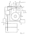
- FIG. 5 schematically shows an advantageous device for testing liquid fuel, especially fuel oil on its potential erosive effect when burning in a heating system shown.
- This one has one Fuel tank 45 for a fuel sample, one to the fuel tank 45th connected fuel pump 13 and two after the fuel pump 13th arranged nozzles 15, 16.
- the first nozzle 15 has a cone characteristic a common angle for spraying fuel.
- the second nozzle 16 Fuel injects fuel specifically to the test area 31. It has a characteristic with it a sharp cone angle of a few degrees.
- a Voltage converter 47 and one connected to the voltage converter 47 Electrode 25 available.
- a fan 23 for a fresh air supply and a Control 51 for controlling the fuel pump 13, the voltage converter 47th and the fan 23 complete the testing apparatus.
- a replaceable metal test surface 31 in FIG Arranged area of the flame This is grounded.
- a temperature sensor 49 the oil temperature can be monitored.
- an infrared sensor 50 the Temperature of the test area 31 are monitored.
- the flame is a combustion chamber within a combustion chamber wall 53 present, whose design is of minor importance. So that Flame burns quietly, a flame tube 55 is available.
- the fresh air is through the Blower 23 is blown against a baffle plate 57.
- This has a central Air opening in which the first nozzle is arranged such that around the first nozzle 15 there is a ring opening.
- Axial in the flow direction of the air is the Test area 31 is arranged. Near and in front of the test area 31 is an electrode 25 arranged with, for example, 12,000 volts DC or AC voltage the current transformer 47 can be provided.
- the second nozzle 16 is on the Test surface 31 directed, in such a way that the injected through the second nozzle Fuel approximately centrally impinges on the test surface 31 and wets them. Thus is this location of the test area 31 by the air flow and the wetting fuel cooled. It is in the immediate vicinity of or in the field of tension strong exposed area of the plasma. This spot is also illuminated by the infrared sensor supervised.
- the controller 51 may after a timer regularly the fan 23, the Oil pump 13, possibly an unillustrated valve for controlling the nozzles 15,16 and drive the current transformer 47. You can also do this because of Control fair values.
- the measured value is in particular the temperature of the Test area 31 in question. So the test procedure sequence can be started as soon as the temperature sensor of the test area, for example 250, 300, 350 or 380 degrees measures. The sequence can be terminated if the test area is 550, 600 or 650 Degree measures.
- the fuel may also be applied to a test area be applied, which is electrically preheated.
- the test area can be off consist of an Alloy strip, which is connected to a power source and so on directly heated or indirectly heated with a heating coil.
- the fuel can be poured onto the test surface, dropped or sprayed on.
- the Evaporation or evaporation of the fuel takes place thanks to the Heat energy supply to the test area. This allows the test surface to be controlled to run repeatedly through the desired temperature profile.
- a fuel sample checked.
- the fuel with the nozzle 15 in the Carburetor tube 31 sprayed.
- the fuel becomes thanks to existing Residual heat or the energy supplied to the electrodes gassed and am Spark ignited.
- the plasma is a electrical voltage field of twice 7500 volts alternating voltage exposed. Thanks to the low sulfur content, the presence of the blower are injected oxygen-rich fresh air and the electric field the combustion conditions such that eroded at the carburetor 31 very quickly Jobs arise.
- a preferred sequence has 2 minutes burn time, that of 3 minutes Afterbreathing is followed.
- the Vorzündzeit overlaps the Nachlstructurezeit and is short, for example 2 seconds.
- the fuel pump will start for 2 minutes, during which the grounded test surface is sprayed.
- the oil supply is a voltage of about 15,000 volts from the earth on the given only electrode.
- the errosivity of the fuel can be at this Test equipment to be assessed after about 3 days of the trial period.
Abstract
Description
In jüngster Zeit sind schwefelarme Heizöle auf den Markt gekommen, die einen Massenanteil an Schwefel von 0,05 bis 0,001 % aufweisen. Bei der Verwendung solcher schwefelarmer Heizöle treten bisher unbekannte Schadensbilder an den Metallteilen im Kesselraum und am Ölbrenner, insbesondere am Flammbecher auf. Die Schadensbilder treten auch in Brennwert-Heizanlagen auf, die die Kondensationswärme nutzen und mit Niedertemperatur-Brennern, sog. Gebläse-Blaubrennern ausgerüstet sind. Die Schadensbilder zeigen scharf umrissene, kraterförmig erodierte Stellen mit einer fein gekörnten Oberfläche und unterscheiden sich deutlich von einer Hochtemperaturkorrosion. Derartige Schadensbilder können bereits innerhalb weniger Wochen nach Inbetriebnahme der Heizungsanlage entstehen. Die Wahl von korrosionsbeständigeren Materialien hat nur bedingt Einfluss auf die Schadensbilder.Recently, low-sulfur heating oils have come on the market, the one Having a sulfur content of 0.05 to 0.001%. When using Such low-sulfur heating oils occur previously unknown damage to the Metal parts in the boiler room and the oil burner, especially on the flame cup on. The damage also occurs in condensing heating systems, which the Use condensation heat and with low-temperature burners, so-called fan blue burners are equipped. The damage pictures show sharply outlined, crater-shaped eroded areas with a finely grained surface and distinguish distinct from high-temperature corrosion. Such damage can within a few weeks of start-up of the heating system arise. The choice of more corrosion-resistant materials has only limited Influence on the damage pictures.
Es ist daher Aufgabe der Erfindung Mittel und Wege zu finden, die neuartigen Schadensbilder an Heizungsanlagen bei der Verwendung von Heizöl mit einem Schwefelgehalte von 0,05 und weniger zu verhindern oder zu vermindern.It is therefore an object of the invention to find ways and means, the novel Damage to heating systems when using fuel oil with a Sulfur levels of 0.05 and less to prevent or reduce.
In einer Versuchsreihe mit sieben Brennstoffmarken unterschiedlicher Herkunft konnte festgestellt werden, dass die Herkunft des Brennstoffs entscheidenden Einfluss hat auf seine erosive Wirkung. Heizöle mit identischem Schwefelgehalt, jedoch unterschiedlicher Herkunft zeigten unterschiedliche Erosivität. Vergleiche der chemischen und physikalischen Analysen der unterschiedlichen Brennstoffe ergaben bisher keine schlüssigen Resultate über die Ursache der unterschiedlichen Erosivität. Es wird vermutet, dass der Raffinerieprozess oder die Ölquelle die Heizölqualität derart beeinflusst, dass eine Erosion auftritt oder nicht auftritt.In a test series with seven fuel brands of different origin could be determined that the origin of the fuel is crucial Influence on its erosive effect. Fuel oils with identical sulfur content, However, different origins showed different erosivity. Comparisons of chemical and physical analyzes of different fuels so far, no conclusive results on the cause of the different erosivity. It is believed that the refinery process or the oil well is the fuel oil quality influenced so that erosion occurs or does not occur.
Erfindungsgemäss wird daher vorgeschlagen, zur Vermeidung der Erosionsschäden in Heizungsanlagen den flüssigen, schwefelarmen Brennstoff, z.B. chargenweise durch eine neutrale Stelle oder in der Raffinerie, auf seine potentielle erosive Wirkung beim Verbrennen in Heizungsanlagen zu prüfen. Zur Prüfung des Brennstoffes wird vorteilhaft der Brennstoff in Verbrennungsluft nahe einer Prüffläche vernebelt und der Brennstoffnebel einem elektrischen Spannungsfeld ausgesetzt und entflammt.According to the invention is therefore proposed to avoid the erosion damage in heating systems, the liquid, low-sulfur fuel, e.g. batch through a neutral body or in the refinery, to its potential erosive To test the effect of burning in heating systems. To examine the Fuel will advantageously be the fuel in combustion air near one Test area fogged and the fuel mist an electric field of tension exposed and inflamed.
Weshalb dabei an metallischen Prüfflächen eine von blossem Auge sichtbare Erosion bereits nach kurzer Zeit auftritt, ist im Detail nicht bekannt. Es kann dies jedoch folgendermassen erklärt werden: Bekanntlich entsteht bei der Verbrennung von schwefelarmem Heizöl in der Dampf/Flüssigphase und bei Anwesenheit von Sauerstoff Carbonsäure. Es wird vermutet, dass diese Carbonsäure die Metalloxidschicht (überwiegend Eisenoxid), die das Metall schützt, angreift und zerstört und an diesen Stellen ohne Metalloxidschicht das blanke Metall erodiert wird. Es wird weiter angenommen, dass bei der Zündung solch erosiven Heizöls in Gegenwart des elektrischen Spannungsfeldes des Zündfunkens Ionen des Plasmas, gleich anschliessend an deren Entstehung, gegen die Metallfläche schiessen und bei ihrem Aufprall diese erodieren.Which is why metallic erosion surfaces cause erosion visible to the naked eye already occurs after a short time, is not known in detail. It can, however be explained as follows: As is known in the combustion of Low sulfur fuel oil in the vapor / liquid phase and in the presence of Oxygen carboxylic acid. It is believed that this carboxylic acid the Metal oxide layer (predominantly iron oxide), which protects the metal, attacks and destroyed and eroded in these places without metal oxide layer, the bare metal becomes. It is further assumed that at the time of ignition of such erosive fuel oil in Presence of the electric field of ignition of the plasma ions, Immediately after their formation, shoot against the metal surface and at their impact will erode them.
Es konnte festgestellt werden, dass bei einer mit einer Kohlenschicht versehenen Prüffläche Schadensbilder rascher auftreten als bei blanken Prüfflächen. Scheinbar wird die Bildung von Carbonsäure durch die Anwesenheit einer Kohlenschicht auf der metallischen Oberfläche begünstigt. Die Kohlenschicht braucht dabei lediglich einige µ stark zu sein. Eine ausreichende Schichtstärke wird auf 10 bis 15 µ geschätzt.It could be stated that in case of a coal layer Test surface damage patterns occur more quickly than with bare test surfaces. Seemingly The formation of carboxylic acid is due to the presence of a layer of carbon the metallic surface favors. The carbon layer only needs it a few μ to be strong. A sufficient layer thickness is estimated to be 10 to 15 μ.
Es konnte ferner festgestellt werden, dass das Durchfahren eines Temperaturbereiches notwendig ist. Dieser Temperaturbereich liegt sicher zwischen 350 und 600 °C. Ein eingeschränkter Temperaturbereich liegt zwischen 370 und 550 °C. In diesem Temperaturbereich treten die Prozesse auf, die das Schadensbild verursachen. Aufgrund von weiteren Untersuchungen ist dieser Temperaturbereich möglicherweise noch präziser einschränkbar. Es konnte weiter beobachtet werden, dass die Schadensbilder beschleunigt an Stellen auftreten, die durch den Brennstoff benetzt werden.It was also found that driving through a Temperature range is necessary. This temperature range is safe between 350 and 600 ° C. A limited temperature range is between 370 and 550 ° C. In this temperature range, the processes occur, the damage pattern cause. Due to further investigations this temperature range is possibly even more precise restrictable. It could be further observed that the damage patterns accelerate in places that occur due to the fuel be wetted.
Ein Prüfungsverfahren zur Prüfung von flüssigem Brennstoff auf dessen potentielle erosive Wirkung beim Verbrennen in Heizungsanlagen zeichnet sich vorteilhaft durch eine mehrfache Wiederholung einer Sequenz von Verfahrensschritten aus, welche Sequenz folgende Merkmale aufweist:
- Vernebeln von Brennstoff und vermischen von Brennstoffnebel und Verbrennungsluft,
- ein elektrisches Spannungsfeld errichten und den Brennstoffnebel dem Spannungsfeld aussetzen.
- Zünden des versprühten Brennstoffes, so dass ein Plasma entsteht,
- Aufrechterhalten des elektrischen Spannungsfelds und das Plasma dem elektrischen Spannungsfeld aussetzen,
- Abstellen der Brennstoffzufuhr.
- Misting of fuel and mixing of fuel mist and combustion air,
- establish an electric field of tension and expose the fuel mist to the field of tension.
- Igniting the sprayed fuel, creating a plasma,
- Maintain the electric field and expose the plasma to the electric field,
- Stop the fuel supply.
Dabei wird vorteilhaft beim Starten des Prüfverfahrens Heizöl verwendet, das eine zum Starten geeignete Temperatur aufweist. Sobald der Verbrennungsprozess Hitze entwickelt, wird vorteilhaft auf gekühltes Heizöl umgestellt. Das gekühlte Heizöl kann vorteilhaft mit einem Fliessverbesserer versetzt sein, damit es möglichst kühl, z.B. bei minus 10 °C verwendet werden kann. Dank einem gekühlten Brennstoff wird die Prüffläche möglichst lange benetzt.It is advantageous when starting the test method used heating oil, the one has suitable temperature for starting. Once the combustion process heat developed, is advantageously converted to cooled fuel oil. The cooled fuel oil may advantageously be mixed with a flow improver to keep it as cool as possible, e.g. can be used at minus 10 ° C. Thanks to a cooled fuel will wetted the test area as long as possible.
Obige Sequenz kann vorteilhaft mit einem weiteren Verfahrensschritt ergänzt werden, in welchem vorhandene Prüfflächen gekühlt werden. Zum Kühlen nach Abstellen der Brennstoffzufuhr wird vorteilhaft Luft verwendet.The above sequence can be advantageously supplemented with a further process step in which existing test areas are cooled. To cool down Turning off the fuel supply is advantageously used air.
Zur Überprüfung des Ionenbeschusses wird vorteilhaft eine metallene Prüffläche verwendet. Diese ist zweckmässigerweise aus einem für den Brennerbau geeigneten Material, z. B. Alloy 601, gefertigt. Die Prüffläche ist vorteilhaft in einen Brenner, z.B. in einen Verdampfer eingesetzt. Die Prüffläche kann die innere Oberfläche eines Flammbechers sein. Sie kann auch die Oberfläche eines Verdampfers sein. Sie kann insbesondere auch eine Oberfläche eines herkömmlichen Brenners sein.To check the ion bombardment is advantageously a metal test surface used. This is expediently from a suitable for burner construction Material, eg. B. Alloy 601 manufactured. The test surface is advantageously in a burner, e.g. used in an evaporator. The test surface may be the inner surface of a Flammbechers be. It can also be the surface of an evaporator. she can in particular also be a surface of a conventional burner.
Die Zündung erfolgt vorteilhaft durch einen Zündfunken. Dadurch können für die Zündung die Elektroden verwendet werden, die zur Errichtung eines Spannungsfelds ohnehin benötigt werden, und das Spannungsfeld ist in diesem Fall mit Sicherheit schon vorhanden, wenn das Plasma entsteht. Die Elektroden können mit einer Wechselspannung versorgt sein, oder eine konstante Potentialdifferenz aufweisen. Das Spannungsfeld kann zwischen zwei Elektroden aufgebaut werden, während die Prüffläche geerdet ist. Es kann auch zwischen einer Elektrode und der Prüffläche aufgebaut werden, so dass die Prüffläche eine Elektrode bildet. Diese die Prüffläche bildende Elektrode ist vorteilhaft aus Flachmaterial gefertigt.The ignition is advantageously carried out by a spark. This allows for the Ignition the electrodes are used to build a Tension field are needed anyway, and the field of tension is in this case certainly already present when the plasma is created. The electrodes can be supplied with an AC voltage, or a constant potential difference exhibit. The stress field can be built up between two electrodes, while the test area is grounded. It can also be between an electrode and the Test surface are constructed so that the test surface forms an electrode. These the Test surface forming electrode is advantageously made of flat material.
In einer Heizanlage erfolgt eine Ölzufuhr vorschriftsmässig erst nach einer Vorzündzeit von 10 bis 15 Sekunden. Dies kann beim erfindungsgemässen Prüfverfahren ebenso gehandhabt werden. Wesentlich ist, dass das Plasma einem elektrischen Spannungsfeld ausgesetzt sind. Vorzugsweise ist das Spannungsfeld während dem Entstehen der Flamme bereits aufgebaut. In a heating system, an oil supply is done according to regulations only after one Pre-ignition time of 10 to 15 seconds. This can in the inventive Test methods are handled as well. It is essential that the plasma one are exposed to electrical stress. Preferably, the stress field already built up during the emergence of the flame.
Es wurde gefunden, dass je länger in einer Heizanlage die Nachzündzeit eingestellt ist und der Zündfunken bzw. das Spannungsfeld gleichzeitig mit der Flamme aufrechterhalten bleibt, desto grösser ist die erodierende Wirkung eines Schadenbilder hervorrufenden Brennstoffes an benachbarten Metallteilen. Vorteilhaft wird daher beim Prüfverfahren in einer Sequenz während mehr als 35 sec., vorteilhaft bis zum Abstellen der Ölzufuhr, ein elektrisches Spannungsfeld aufrechterhalten.It was found that the longer in a heating system, the Nachzündzeit set is and the spark or the voltage field simultaneously with the flame is maintained, the greater is the eroding effect of a Damage causing fuel to adjacent metal parts. Advantageous is therefore used in the test procedure in a sequence for more than 35 sec., advantageous until the shutdown of the oil supply, an electric field of tension maintained.
Da die Erosion nahe der Elektrode oder Elektroden grösser ist als an entfernteren Stellen, sind beim Prüfverfahren die Elektroden oder ist die Elektrode vorteilhaft in einem Abstand von weniger als 50 mm, vorteilhaft in einem Abstand von weniger als 15 mm, oder gar in einem Abstand von 3 bis 7 mm von der metallenen Prüffläche, bzw. der Stelle der Prüffläche, nahe der die Ionisation des Brennstoffes geschieht. Die Spannung und der Abstand zwischen den Spannungspotentialen sind einander reziprok entsprechend derart zu wählen, dass ein möglichst grosses Volumen des Plasmas einer möglichst hohen Spannung ausgesetzt ist.Because erosion is greater near the electrode or electrodes than at more distant ones Make, are in the test method, the electrodes or the electrode is advantageous in a distance of less than 50 mm, advantageously at a distance of less than 15 mm, or even at a distance of 3 to 7 mm from the metal test surface, or the location of the test area near which the ionization of the fuel occurs. The Voltage and the distance between the voltage potentials are each other Accordingly, reciprocally to choose such that the largest possible volume of the Plasma is exposed to the highest possible voltage.
Je höher die Spannung des Spannungsfeldes ist, desto höher ist die Wahrscheinlichkeit, dass der Schadenbilder hervorrufende Brennstoff ein solches Schadenbild hervorruft. Daher wird das Plasma vorteilhaft einer Spannung von 2 mal 7500 V und mehr, vorzugsweise von wenigstens 2 mal 10'000 V, besonders bevorzugt von wenigstens 2 mal 15'000 Volt ausgesetzt. Es konnte jedoch festgestellt werden, dass einzelne Brennstoffe schon bei Spannungen von 200 V oder 230 V Schadenbilder hervorrufen.The higher the voltage field voltage, the higher the voltage Likelihood that the fuel-causing fuel is one such Causes damage. Therefore, the plasma advantageously becomes a voltage of 2 times 7500 V and more, preferably at least 2 times 10'000 V, especially preferably exposed to at least 2 times 15,000 volts. It could be determined, however be that individual fuels already at voltages of 200 V or 230 V. Cause damage.
Es konnte an Heizungsanlagen für schwefelarmes Heizöl extra leicht (Schwefelgehalt < 0.5 ppm) beobachtet werden, dass im Sprühschatten der Zündelektroden weniger Schadensbilder auftreten. Daher wird beim Prüfverfahren vorteilhaft eine im Flammenbereich angeordnete Metallfläche mit dem Heizöl besprüht oder gar benetzt. Damit die Ionisation des Brennstoffes möglichst lange nahe der Prüffläche eintritt, wird der Flammbecher oder eine andere Prüffläche vor dem Beginn einer neuen Sequenz vorteilhaft auf eine Temperatur unter 250°C, vorzugsweise unter 220°C, besonders bevorzugt unter 200°C abgekühlt. Eine Kühlung geschieht vorzugsweise durch Nachlüften während einigen Sekunden oder Minuten. Die Prüffläche ist zwecks Kühlung vorteilhaft axial im Frischluftstrom angeordnet. Vorteilhaft wird die Prüffläche während der gesamten Brenndauer gekühlt. Durch die Abkühlung zwischen den Sequenzen unter 250 Grad wird erreicht, dass bei der nächsten Sequenz die Prüffläche einen Temperaturbereich von 350 bis 550 oder 600 °C durchlaufen muss. Durch die Wahl der Sequenzlänge wird erreicht, dass die Prüffläche 550 bis 600 Grad erreicht, jedoch der Prozess nicht unnötig lange bei heisseren und daher weniger effizienten Temperaturen weitergeführt wird.It could be used on heating systems for low-sulfur fuel oil extra light (sulfur content <0.5 ppm) observed that in the spray shadow of the ignition electrodes less Damage pictures occur. Therefore, in the test method, an advantageous in Flame area arranged metal surface sprayed with the fuel oil or even wetted. So that the ionization of the fuel as long as possible near the test area occurs, the Flammbecher or another test area before the beginning of a new sequence advantageous to a temperature below 250 ° C, preferably below 220 ° C, more preferably cooled below 200 ° C. A cooling happens preferably by post-ventilation for a few seconds or minutes. The Test surface is advantageously arranged axially in the fresh air flow for the purpose of cooling. Advantageously, the test surface is cooled during the entire burning time. By the cooling between the sequences below 250 degrees is achieved at the Next, the test area has a temperature range of 350 to 550 or 600 ° C has to go through. By choosing the sequence length is achieved that the Test area reached 550 to 600 degrees, however, the process did not last unnecessarily long Higher and therefore less efficient temperatures continue.
Je kürzer die Verbrennungsphase einer Sequenz dauert, desto weniger erhitzt sich die Umgebung der Flamme. Je länger das Prüfverfahren bei niedriger Temperatur des Flammbechers oder einer anderen Prüffläche abläuft, desto grösser ist der Zeitanteil, während dem die erodierende Metallfläche benetzt wird und die Bedingungen für die erodierende Wirkung des Brennstoffes optimal sind. Daher wird vorteilhaft eine Sequenz kurz gewählt, so dass sie weniger als 15 Minuten dauert, vorteilhaft weniger als 10 Minuten, besonders bevorzugt weniger als 5 Minuten. Dadurch kann der erosionswirksame Zeitanteil pro Stunde erhöht werden.The shorter the combustion phase of a sequence, the less it heats up the environment of the flame. The longer the test procedure at low temperature of the flame cup or other test surface, the greater is the Time proportion during which the eroding metal surface is wetted and the Conditions for the eroding effect of the fuel are optimal. Therefore Advantageously, a sequence is chosen short so that it takes less than 15 minutes advantageously less than 10 minutes, more preferably less than 5 Minutes. As a result, the erosion-effective time share per hour can be increased.
Mit einem solchen Verfahren kann eine Heizöl-Probe innerhalb von höchstens 30 bis 40 Betriebsstunden (Brenndauer) auf ihre erodierende Wirkung überprüft werden. Es ist zu erwarten, dass durch eine Optimierung des Prüfverfahrens diese Betriebszeit noch weiter verkürzt werden kann. Je nach Eigenschaften der Probe tritt eine erste von blossem Auge sichtbare Erosion bereits nach wenigen Betriebsstunden auf.With such a method, a fuel oil sample can be within a maximum of 30 to 40 operating hours (burning time) to be checked for their eroding effect. It It is expected that by optimizing the test procedure this operating time can be shortened even further. Depending on the properties of the sample, a first occurs erosion visible to the naked eye after only a few hours of operation.
Eine erodierte oder nach z.B. 40 Stunden noch immer nicht erodierte Prüffläche wird zweckmässigerweise als Beleg der Heizölqualität einer Charge archiviert. Für jede zu prüfende Charge wird daher vorteilhaft eine neue Prüffläche in einer Prüfvorrichtung angeordnet. Diese Prüffläche kann vorgängig mit einer Kohlenschicht versehen werden. Es kann aber auch beim Starten des Prozesses die Verbrennung derart beeinflusst werden, dass sich eine Kohlenschicht auf der Prüffläche bildet.An eroded or after e.g. 40 hours still not eroded test area is conveniently archived as a record of the fuel oil quality of a batch. For everyone too testing batch will therefore be beneficial to a new test area in one Test device arranged. This test surface can be preceded by a Coal layer be provided. But it can also start the process Combustion be influenced so that a layer of carbon on the Test surface forms.
Zur Prüfung von Heizöl oder anderen flüssigen Brennstoffen auf deren potentielle erosive Wirkung beim Verbrennen in Heizungsanlagen, insbesondere in Brennwert-Heizungsanlagen, d.h. bei Heizanlagen, in denen bei der Verbrennung entstehender Wasserdampf an der Kesselwandung kondensiert, wird erfindungsgemäss eine Vorrichtung verwendet, welche wenigstens folgendes aufweist: Einen Brennstoffbehälter für eine Brennstoffprobe, eine an den Brennstoffbehälter angeschlossenen Brennstoffpumpe, eine nach der Brennstoffpumpe angeordnete Düse zum Versprühen von Brennstoff, einen Spannungswandler, wenigstens eine mit dem Spannungswandler verbundene Elektrode, einen Ventilator für eine Frischluftzufuhr, eine Steuerung zur Steuerung der Brennstoffpumpe, des Spannungswandlers und des Ventilators, sowie eine einfach aus der Vorrichtung entfernbare und in die Vorrichtung einsetzbare Prüffläche. Bei einer solchen Vorrichtung kann ein Feuerungsraum oder Kessel gänzlich fehlen. Vorteilhaft ist jedoch ein Temperaturfühler zum Messen der Temperatur der Prüffläche vorhanden. Vorteilhaft ist ferner die Prüffläche metallisch und bevorzugt mit einem Kohlenstofffilm versehen.For testing heating oil or other liquid fuels for their potential erosive effect when burning in heating systems, in particular in condensing heating systems, i.e. in heating systems where combustion occurs Steam condenses on the boiler wall, according to the invention a Device having at least the following: One Fuel tank for a fuel sample, one to the fuel tank connected fuel pump, one arranged after the fuel pump Nozzle for spraying fuel, a voltage converter, at least one connected to the voltage converter electrode, a fan for a Fresh air supply, a control for controlling the fuel pump, the Voltage converter and the fan, as well as a simple out of the device Removable and applicable in the device test surface. In such a Device may lack a firebox or boiler altogether. Is advantageous However, a temperature sensor for measuring the temperature of the test area available. Furthermore, the test surface is advantageously metallic and preferably with a Provided carbon film.
Es wurde gefunden, dass eine Erosion der Prüffläche an Stellen, die Spuren von Filzstiften aufwiesen oder an Prüfflächen, die mit Werkzeugen aus Buntmetall bearbeitet wurden rascher auftrat. Es wird daraus geschlossen, dass Metalloxide, insbesondere Oxide von Nicht-Eisen-Metallen, an der Oberfläche der Prüffläche die Erosion begünstigen. Daher wird die Prüffläche vor dem Prüfverfahren vorteilhaft mit einem Metalloxid behandelt. Die Prüffläche kann auch mit Metallstaub behandelt werden, der dann bei der Verbrennung von Brennstoff oxidiert.It was found that erosion of the test area in places containing traces of Felt pens or test surfaces made with non-ferrous metal tools were processed faster occurred. It is concluded that metal oxides, especially oxides of non-ferrous metals, on the surface of the test area the Favor erosion. Therefore, the test area becomes advantageous before the test procedure treated with a metal oxide. The test area can also be treated with metal dust which then oxidizes upon combustion of fuel.
Die Steuerung ist vorteilhaft derart ausgelegt, dass sie eine Vielzahl der beschriebenen Sequenzen automatisch steuert.The controller is advantageously designed so that it a variety of automatically controls the sequences described.
Der Spannungswandler ist dabei vorteilhaft derart dimensioniert, dass er eine Spannung von zweimal mehr als 7'500 V, vorzugsweise zweimal mehr als 10'000 V, besonders bevorzugt von zweimal mehr als 15'000 Volt generiert. Herkömmliche Spannungswandler für Heizungsanlagen sind auf eine Spannung von zweimal 7500 Volt, eine Vorzündzeit von 12 sec. und eine Nachzündzeit von ca. 20 sec. ausgelegt. Für eine Prüfvorrichtung ist er jedoch vorteilhaft derart ausgelegt, dass er die Spannung über einen Zeitraum von mehr als 35 sec., vorzugsweise mehr als einer Minute, besonders bevorzugt praktisch unbegrenzt aufrecht erhalten kann. Die Spannung kann auch gegenüber der Erde als zweitem Potential aufgebaut werden. Es kann auch, allenfalls zusätzlich zur Spannung zwischen den Elektroden, eine konstante Potenzialdifferenz zwischen einer separaten Elektrode und der geerdeten oder unter Spannung gesetzten Prüffläche aufrecht erhalten werden. Es kann auch die Prüffläche gegenüber der Erde unter Spannung gesetzt werden. Durch eine dadurch erreichte Spannungsdifferenz zwischen der Prüffläche und anderen Teilen in der Umgebung des Plasmas kann der Ionenfluss gesteuert werden.The voltage converter is advantageously dimensioned such that it has a Voltage of twice more than 7,500 V, preferably twice more than 10,000 V, particularly preferably generated by twice more than 15,000 volts. conventional Voltage transformers for heating systems are at a voltage of twice 7500 Volts, a pre-ignition of 12 sec. And a Nachzündzeit of about 20 sec. Designed. For a tester, however, it is advantageously designed so that it Voltage over a period of more than 35 sec., Preferably more than one Minute, particularly preferably practically unlimited can sustain. The Voltage can also be built up against the earth as the second potential. It may also, at most in addition to the voltage between the electrodes, a constant potential difference between a separate electrode and grounded or under tensioned test surface. It can also the test surface is put under tension with respect to the earth. By a This achieved voltage difference between the test area and other parts in the vicinity of the plasma, the ion flux can be controlled.
Die Elektrode ist, bzw. die Elektroden sind vorteilhaft in einem Abstand von weniger als 50 mm, vorteilhaft in einem Abstand von weniger als 15 mm von einer metallenen Prüffläche angeordnet. Vorteilhaft ist ein Temperaturfühler vorhanden, mit dem die Temperatur der Prüffläche überwacht werden kann. The electrode is, or the electrodes are advantageously at a distance of less than 50 mm, advantageously at a distance of less than 15 mm from one metal test surface arranged. Advantageously, a temperature sensor is available with which the temperature of the test area can be monitored.
Die Düse und die Prüffläche sind vorteilhaft so angeordnet und die Düse weist eine derartige Charakteristik auf, dass gewährleistet ist, dass der Brennstoff gegen die im Bereich der Flamme angeordnete Prüffläche spritzt und der Brennstoff die Prüffläche benetzt und nahe der Prüffläche in ein Plasma übergeht. Es kann eine erste Düse für eine die Flamme aufrechterhaltende Brennstoffzufuhr zur Flamme und eine zweite Düse zur Besprühung oder Benetzung der Prüffläche vorhanden sein. Die metallene Prüffläche ist vorteilhaft aus einem Edelstahl gefertigt, z.B. Alloy 601, DIN 2.4851, der gewährleistet, dass keine Hochtemperaturkorrosion auftritt. Dadurch ist ein auftretendes Schadensbild eindeutig der Erosion und der Qualität des geprüften Brennstoffs zuzuordnen.The nozzle and the test surface are advantageously arranged and the nozzle has a such characteristic that it is ensured that the fuel is resistant to the Area of flame arranged test surface sprays and the fuel the test surface wetted and passes into a plasma near the test area. It can be a first nozzle for a flame maintaining fuel supply to the flame and a second Nozzle for spraying or wetting the test surface be present. The metal ones Test surface is advantageously made of a stainless steel, e.g. Alloy 601, DIN 2.4851, which ensures that no high-temperature corrosion occurs. This is one damage pattern clearly reflects the erosion and quality of the tested Attributable to fuel.
Zur Vermeidung des Schadens kann nicht nur die Erosivität des Brennstoffs überprüft werden. Es können dem Brennstoff bei Bedarf, d.h. bei zu hoher Erosivität einer Charge, Antioxidantien beigemischt werden. Antioxidatien verhindern, wie auch ein Schwefelgehalt von über 0,4 bis 0,5%m/m, die Bildung von Carbonsäure. Ferner kann dem Heizöl ein Additiv zugesetzt werden, das gewährleistet, dass die elektrostatischen Ladungen bei der Verbrennung gering bleiben. Ein solches "Static Dissipator Additive" ist beispielsweise das bisher in Flugbezin verwendete "Stadis 450". Ob die Dosierung der Additive ausreicht wird vorteilhaft mittels des beschriebenen Prüfverfahrens überprüft.To avoid the damage can not only the erosiveness of the fuel be checked. If required, i. with too much erosivity a batch, antioxidants are added. Prevent antioxidants, like also a sulfur content of over 0.4 to 0.5% m / m, the formation of carboxylic acid. Furthermore, an additive can be added to the heating oil, which ensures that the Electrostatic charges remain low during combustion. Such a "static Dissipator additives "is for example the so far used in Flugbezin" Stadis 450 ". Whether the dosage of the additives is sufficient is advantageous by means of the tested test method.
Es wird auf Grund der Feststellung der erhöhten Erosivität des Brennstoffes bei Anwesenheit von Metalloxiden auch vermutet, dass zur Entschwefelung des Brennstoffes eingesetzte Metalloxide in Spuren im Brennstoff verbleiben und eine Erosion begünstigen. Daher kann zur Verhinderung der Erosion der Metalloxidgehalt der im Brennstoff reduziert oder deren Aggressivität durch eine Zugabe von Antioxidantien neutralisiert werden. Es wird daher angenommen, dass die Bemessung der Zugabemenge von Antioxidantien aufgrund einer Messung des Metalloxidgehalts des Brennstoffes vorgenommen werden kann.It is due to the finding of increased erosivity of the fuel Presence of metal oxides also suspected that desulfurization of the Fuel used metal oxides remain in traces in the fuel and a Favor erosion. Therefore, to prevent erosion of Metal oxide content reduced in the fuel or its aggressiveness by a Addition of antioxidants are neutralized. It is therefore assumed that the measurement of the added amount of antioxidants based on a measurement of the Metalloxidgehalts of the fuel can be made.
Eine weitere Massnahme zur Verhinderung der beschriebenen Erosion besteht darin, den Brennstoff mit einer Glühzündung zu entzünden und so die elektrische Spannung im Brennraum möglichst gering zu halten. Ein vorteilhafter Blaubrenner ist daher mit einer Glühzündung, insbesondere mit einer Niedervolt-Glühzündung ausgerüstet. Dadurch wird verhindert, dass Ionen in grosser Zahl in einem Spannungsfeld beschleunigt werden, auf das Metall aufprallen und dadurch dessen Oberfläche erodieren. Another measure to prevent the erosion described is to to ignite the fuel with a glow ignition and so the electric Keep voltage in the combustion chamber as low as possible. An advantageous blue flame burner is therefore with a glow ignition, in particular with a low-voltage glow ignition equipped. This prevents large numbers of ions in one Stress field can be accelerated, impact the metal and thereby its Erode surface.
Alle diese Massnahmen basieren auf der Erkenntnis, dass auf den die zu vermeidenden Schadensbilder verursachenden Prozess in zweierlei Hinsicht Einfluss genommen werden kann, nämlich: 1. durch Verminderung einer elektrischen Spannung im Verbrennungsraum, und 2. durch die Verminderung der Bildung von Carbonsäure. Fehlt lediglich einer der genannten Faktoren, so ist das Schadensrisiko bereits wesentlich vermindert. Wie und weshalb die Brennstoffeigenschaften, die in jeder Charge wieder anders sein können, bei dem schadenden Prozess beteiligt sind, ist noch nicht erkennbar.All of these measures are based on the knowledge that they are based on avoiding damage-causing process in two ways influence can be taken, namely: 1. by reducing an electrical Stress in the combustion chamber, and 2. by reducing the formation of Carboxylic acid. If only one of these factors is missing, then the risk of damage is already significantly reduced. How and why the fuel properties in each batch may be different again, involved in the damaging process, is not recognizable yet.
Es zeigt:
- Fig. 1
- eine teilweise geschnittene Seitenansicht eines Brenners für eine erfindungsgemässe Prüfvorrichtung,
- Fig. 2
- Seitenansicht des Brennerkopfes,
- Fig. 3
- Frontalansicht des Brennerkopfes,
- Fig. 4
- eine geschnittenen Darstellung des Brennerkopfes,
- Fig. 5
- eine schematische Darstellung einer Prüfvorrichtung.
- Fig. 1
- a partially sectioned side view of a burner for a test device according to the invention,
- Fig. 2
- Side view of the burner head,
- Fig. 3
- Frontal view of the burner head,
- Fig. 4
- a sectional view of the burner head,
- Fig. 5
- a schematic representation of a tester.
Der Brenner 11 gemäss Figur 1 weist eine Brennstoffpumpe 13 auf, mit der der
Brennstoff aus einem nicht dargestellten Behälter der Brennstoffdüse 15 zugepumpt
wird. Die Brennstoffdüse 15 ist mit ihrer Düsenöffnung etwa in der Ebene einer
Stauscheibe 17 angeordnet. In der Stauscheibe 17 ist eine zentrale Öffnung
vorhanden, durch die der Brennstoff in einen Verdampfer 19 gespritzt werden kann.
Der Verdampfer 19 ist in einem Flammrohr 21 angeordnet.The
Der Brenner 11 weist zudem einen Ventilator 23 auf. Mit dem Ventilator 23 kann
Frischluft mit einem bestimmten Druck an die Stauscheibe 17 herangeführt werden.
Die Frischluft tritt in der Folge in den Innenraum des Verdampfers 19 ein, wo sie sich
mit verdampftem Brennstoff und mit rezirkulierten Verbrennungsgasen vermischt.
Nicht dargestellt sind Temperaturfühler zur Überwachung der Temperatur des
Brennstoffes und der Prüffläche. Nicht dargestellt ist ein Verbrennungsraum, in
welchem die Flamme brennt.The
Erkennbar sind zwei Zündelektroden 25 nahe der Vergaserwandung. Diese sind an
einen nicht dargestellten Spannungswandler angeschlossen, der die Elektroden mit
einer alternierenden Potentialdifferenz von zweimal 7500 Volt versorgt. Recognizable are two
Der Verdampfer 19 ist in den Figuren 2 bis 4 dargestellt. Er weist ein
Verdampferrohr 31 und einen Flammenteiler 33 auf. Der Flammenteiler 33 ist mit
drei Beinen 35 am Verdampferrohr befestigt. Die Befestigung geschieht über
Blechlappen 37, die an den Beinen 35 ausgeformt sind und in Schlitzen am
Verdampferrohr 31 stecken. Diese eingesteckten Blechlappen 37 können um 20 bis
30° verdreht werden und sind dadurch mit dem Verdampferrohr 31 mechanisch fest
verbunden. Ebenso ist das Verdampferrohr 31 an der Stauscheibe 39 mittels drei in
Schlitzen steckenden und verdrehten Blechlappen 37 befestigt. Dadurch ist das
Verdampferrohr 31 sehr einfach in die Stauscheibe 39 einsetzbar und wieder von der
Stauscheibe 39 entfernbar.The
Im Verdampferrohr sind Abgasrezirkulationsöffnungen 41 vorhanden. Der vom
Verdampferrrohr umschlossene Raum dient der Durchmischung von
Brennstoffdampf, Frischluft und rezirkulierten, sauerstoffarmen Verbrennungsgasen.
Der durch die Düse 15 in diesen Raum eingespritze Brennstoff vergast in diesem
Raum und brennt danach mit einer blauen Flamme mit relativ niedriger Temperatur
und schadstoffarm.In the
Für die Zündung des Brennstoffes sind zwei Elektroden 25 vorhanden, die durch die
Stauscheibe 39 hindurchgeführt sind. In der Stauscheibe 39 ist zudem eine Öffnung
43 für einen Temperaturfühler vorhanden.For the ignition of the fuel, two
In der Figur 5 ist schematisch eine vorteilhafte Vorrichtung zur Prüfung von
flüssigem Brennstoff, insbesondere Heizöl auf dessen potentielle erosive Wirkung
beim Verbrennen in einer Heizungsanlage dargestellt. Diese weist einen
Brennstoffbehälter 45 für eine Brennstoffprobe, eine an den Brennstoffbehälter 45
angeschlossene Brennstoffpumpe 13 und zwei nach der Brennstoffpumpe 13
angeordnete Düsen 15, 16 auf. Die erste Düse 15 weist eine Kegelcharakteristik mit
einem üblichen Winkel zum Versprühen von Brennstoff auf. Die zweite Düse 16
spritzt Brennstoff gezielt auf die Prüffläche 31. Sie weist dazu eine Charakteristik mit
einem spitzen Kegelwinkel von wenigen Graden auf. Ferner ist ein
Spannungswandler 47 und eine mit dem Spannungswandler 47 verbundene
Elektrode 25 vorhanden. Ein Ventilator 23 für eine Frischluftzufuhr und eine
Steuerung 51 zur Steuerung der Brennstoffpumpe 13, des Spannungswandlers 47
und des Ventilators 23 komplettieren den Prüfapparat. Weiter ist in der Vorrichtung
zum Prüfen von flüssigem Brennstoff eine ersetzbare, metallene Prüffläche 31 im
Bereich der Flamme angeordnet. Diese ist geerdet. Mit einem Temperaturfühler 49
kann die Öltemperatur überwacht werden. Mit einem Infrarotfühler 50 kann die
Temperatur der Prüffläche 31 überwacht werden.FIG. 5 schematically shows an advantageous device for testing
liquid fuel, especially fuel oil on its potential erosive effect
when burning in a heating system shown. This one has one
Für die Flamme ist ein Brennraum innerhalb einer Brennraumwandung 53
vorhanden, dessen Ausgestaltung von untergeordneter Bedeutung ist. Damit die
Flamme ruhig brennt, ist ein Flammrohr 55 vorhanden. Die Frischluft wird durch das
Gebläse 23 gegen eine Stauscheibe 57 geblasen. Diese besitzt zentral eine
Luftöffnung, in der die erste Düse derart angeordnet ist, dass rings um die erste Düse
15 eine Ringöffnung vorliegt. Axial in der Strömungsrichtung der Luft ist die
Prüffläche 31 angeordnet. In der Nähe und vor der Prüffläche 31 ist eine Elektrode 25
angeordnet, die mit beispielsweise 12'000 Volt Gleich- oder Wechselspannung aus
dem Stromwandler 47 versehen werden kann. Die zweite Düse 16 ist auf die
Prüffläche 31 gerichtet, und zwar so, dass der durch die zweite Düse eingespritzte
Brennstoff etwa zentral auf die Prüffläche 31 auftrifft und diese benetzt. Somit ist
diese Stelle der Prüffläche 31 durch den Luftstrom und den benetzenden Brennstoff
gekühlt. Sie liegt in unmittelbarer Nähe zum bzw. im dem Spannungsfeld stark
ausgesetzten Bereich des Plasmas. Diese Stelle wird auch durch den Infrarotfühler
überwacht.For the flame is a combustion chamber within a
Die Steuerung 51 kann nach einem Zeitgeber regelmässig den Ventilator 23, die
Ölpumpe 13, eventuell ein nicht dargestelltes Ventil zur Regelung der Düsen 15,16
und den Stromwandler 47 ansteuern. Sie kann diese aber auch aufgrund von
Messewerten ansteuern. Als Messwert kommt insbesondere die Temperatur der
Prüffläche 31 in Frage. So kann die Prüfverfahrens-Sequenz gestartet werden, sobald
der Temperaturfühler der Prüffläche beispielsweise 250, 300, 350 oder 380 Grad
misst. Die Sequenz kann beendet werden, wenn die Prüffläche 550, 600 oder 650
Grad misst.The
Wesentlich an der Prüfungsvorrichtung ist ihre konstant gleichbleibende Ausbildung, die eine Vergleichbarkeit der Resultate gewährleistet.Essential to the testing device is their constant constant Training that ensures comparability of results.
In einer Prüfungsvorrichtung kann auch der Brennstoff auf eine Prüffläche aufgebracht werden, die elektrisch vorgewärmt ist. Dazu kann die Prüffläche aus einem Alloy-Streifen bestehen, der an eine Stromquelle angeschlossen ist und so direkt geheizt ist oder mit einer Heizwicklung indirekt geheizt ist. Der Brennstoff kann auf die Prüffläche aufgegossen, aufgetropft oder aufgesprüht werden. Die Verdunstung oder Verdampfung des Brennstoffes erfolgt dank der Wärmeenergiezufuhr zur Prüffläche. Dies erlaubt, die Prüffläche kontrolliert einen gewünschten Temperaturverlauf wiederholt durchlaufen zu lassen.In an inspection device, the fuel may also be applied to a test area be applied, which is electrically preheated. For this, the test area can be off consist of an Alloy strip, which is connected to a power source and so on directly heated or indirectly heated with a heating coil. The fuel can be poured onto the test surface, dropped or sprayed on. The Evaporation or evaporation of the fuel takes place thanks to the Heat energy supply to the test area. This allows the test surface to be controlled to run repeatedly through the desired temperature profile.
Mit einem in den Figuren dargestellten Brenner 11 wird eine Brennstoffprobe
geprüft. Es sind jedoch auch andere Prüfungsvorrichtungen möglich und sinnvoll.
Zur Prüfung des Brennstoffes wird der Brennstoff mit der Düse 15 in das
Vergaserrohr 31 gesprüht. Im Vergaserrohr wird der Brennstoff dank vorhandener
Restwärme oder der mit den Elektroden zugeführten Energie vergast und am
Zündfunken entflammt. Mit den Zündelektroden wird das Plasma einem
elektrischen Spannungsfeld von zweimal 7500 Volt Wechselspannung ausgesetzt.
Dank dem niedrigen Schwefelgehalt, der Gegenwart der mit dem Gebläse
eingeblasenen sauerstoffreichen Frischluft und dem elektrischen Spannungsfeld sind
die Verbrennungsbedingungen derart, dass am Vergaserrohr 31 sehr rasch erodierte
Stellen entstehen.With a
In der Versuchsphase werden Zyklen von 15 Minuten gewählt, um eine Reproduzierbarkeit der Versuchsreihe zu gewährleisten. Der Versuch wird mit dem Brenner gemäss Figuren 1 bis 4 ausgeführt. Es wird während etwa 15 Sekunden vorgezündet. Danach wird bei laufender Frischluftzufuhr das zu prüfende Heizöl eingespritzt. Es benetzt die innere Oberfläche des Vergaserrohrs. Sofort entzündet es sich am Zündfunken. Das entstehende Plasma wird während der gesamten Brenndauer dem elektrischen Spannungsfeld zwischen den Elektroden ausgesetzt. Während 5 Minuten wird die Flamme so aufrechterhalten und einer Potenzialdifferenz zwischen der Prüffläche und der Elektrode ausgesetzt. Danach wird die Ölzufuhr abgestellt und nachgelüftet. Die Nachlüftzeit beträgt 10 Minuten. Dann beginnt der Zyklus von vorne.In the experimental phase, cycles of 15 minutes are chosen to produce a To ensure reproducibility of the test series. The experiment is with the Burner according to Figures 1 to 4 executed. It will last for about 15 seconds vorgezündet. Thereafter, when the fresh air supply is running, the fuel oil to be tested injected. It wets the inner surface of the carburetor tube. It ignites immediately at the spark. The resulting plasma is released throughout Burning exposed to the electric field between the electrodes. During 5 minutes, the flame is sustained and one Potential difference between the test area and the electrode exposed. After that the oil supply is shut off and relieved. The post-ventilation time is 10 minutes. Then the cycle starts again.
Mit diesem Zyklus sind 20 Minuten Brenndauer innerhalb einer Stunde der
Versuchszeit erosionswirksam. Nach spätestens 120 Stunden oder 5 Tagen
Versuchszeit liegt ein zuverlässiges Prüfungsergebnis vor. Das Verdampferrohr 31
wird ausgebaut und überprüft. Das Ausmass der Erosion gibt Aufschluss über die
erosive Wirkung des Heizöls der geprüften Charge in Heizungsanlagen. Das
Verdampferrohr wird zum Beleg der Brennstoffqualität beschriftet und archiviert.With this cycle, 20 minutes of burning time within one hour are the
Test time erosion effective. After 120 hours or 5 days at the latest
Test time is a reliable test result. The
Es ist zu erwarten, dass mit kürzeren Zyklen von 3 Minuten Brenndauer und 6 Minuten Nachlüftzeit die Versuchszeit verkürzt werden kann. Dies ist darauf zurückzuführen, dass die Erosion in der kühleren Startphase stärker auftritt, solange der Brennstoff die Prüffläche noch flüssig erreicht. Durch geeignete Massnahmen zur Verkürzung der Nachlüftzeit kann die Versuchszeit zusätzlich verkürzt werden.It is expected that with shorter cycles of 3 minutes burning time and 6 Minutes Nachlüftzeit the trial period can be shortened. This is on it attributed to the fact that erosion occurs more in the cooler starting phase, as long as the fuel still reaches the test area liquid. Through suitable measures for Shortening the post-ventilation time can additionally shorten the test time.
Eine bevorzugte Sequenz weist 2 Minuten Brenndauer auf, die von 3 Minuten Nachlüften gefolgt ist. Die Vorzündzeit übergreift die Nachlüftzeit und ist kurz, beispielsweise 2 Sekunden. Danach setzt die Brennstoffpumpe für 2 Minuten ein, während denen die geerdete Prüffläche besprüht wird. Während der gesamten Zeit der Ölzufuhr wird eine Spannung von ca. 15'000 Volt gegenüber der Erde auf die einzige Elektrode gegeben. Die Erosivität des Brennstoffes kann bei dieser Prüfungsanlage nach ca. 3 Tagen der Versuchsdauer beurteilt werden.A preferred sequence has 2 minutes burn time, that of 3 minutes Afterbreathing is followed. The Vorzündzeit overlaps the Nachlüftzeit and is short, for example 2 seconds. After that, the fuel pump will start for 2 minutes, during which the grounded test surface is sprayed. Throughout the time The oil supply is a voltage of about 15,000 volts from the earth on the given only electrode. The errosivity of the fuel can be at this Test equipment to be assessed after about 3 days of the trial period.
Claims (10)
Priority Applications (1)
| Application Number | Priority Date | Filing Date | Title |
|---|---|---|---|
| EP05013646A EP1589338A2 (en) | 2001-09-21 | 2002-09-23 | Method of reducing the damage on heating installations and liquid, low-sulphur fuel |
Applications Claiming Priority (4)
| Application Number | Priority Date | Filing Date | Title |
|---|---|---|---|
| EP01810927 | 2001-09-21 | ||
| EP01810927 | 2001-09-21 | ||
| EP05013646A EP1589338A2 (en) | 2001-09-21 | 2002-09-23 | Method of reducing the damage on heating installations and liquid, low-sulphur fuel |
| EP02762199A EP1466171B1 (en) | 2001-09-21 | 2002-09-23 | Method for reducing damage to heating plants and device for carrying out said method |
Related Parent Applications (2)
| Application Number | Title | Priority Date | Filing Date |
|---|---|---|---|
| EP02762199.4 Division | 2002-09-23 | ||
| EP02762199A Division EP1466171B1 (en) | 2001-09-21 | 2002-09-23 | Method for reducing damage to heating plants and device for carrying out said method |
Publications (1)
| Publication Number | Publication Date |
|---|---|
| EP1589338A2 true EP1589338A2 (en) | 2005-10-26 |
Family
ID=8184153
Family Applications (2)
| Application Number | Title | Priority Date | Filing Date |
|---|---|---|---|
| EP02762199A Expired - Lifetime EP1466171B1 (en) | 2001-09-21 | 2002-09-23 | Method for reducing damage to heating plants and device for carrying out said method |
| EP05013646A Pending EP1589338A2 (en) | 2001-09-21 | 2002-09-23 | Method of reducing the damage on heating installations and liquid, low-sulphur fuel |
Family Applications Before (1)
| Application Number | Title | Priority Date | Filing Date |
|---|---|---|---|
| EP02762199A Expired - Lifetime EP1466171B1 (en) | 2001-09-21 | 2002-09-23 | Method for reducing damage to heating plants and device for carrying out said method |
Country Status (4)
| Country | Link |
|---|---|
| EP (2) | EP1466171B1 (en) |
| AT (1) | ATE326696T1 (en) |
| DE (1) | DE50206846D1 (en) |
| WO (1) | WO2003027668A1 (en) |
Families Citing this family (3)
| Publication number | Priority date | Publication date | Assignee | Title |
|---|---|---|---|---|
| WO2005033253A1 (en) * | 2003-10-07 | 2005-04-14 | Swiss E-Technic Ag | Low-sulfur oil and method for lowering the aggressiveness thereof |
| EP1697735A1 (en) | 2003-12-15 | 2006-09-06 | Swiss E-Technik AG | Method and device for electrically testing fuels and combustibles by generating a plasma |
| DE102009006319B3 (en) * | 2009-01-27 | 2010-10-14 | Chemin Gmbh | Corrosion potential determining method for e.g. coal in fossil-fueled power station, involves analyzing measured process parameters and filling probe, and timely-resolved evaluating corrosion potential of fuel based on analysis |
Family Cites Families (5)
| Publication number | Priority date | Publication date | Assignee | Title |
|---|---|---|---|---|
| JPS5740652A (en) * | 1980-08-22 | 1982-03-06 | Mitsubishi Electric Corp | Corrosion property testing method for insulating oil |
| US5332961A (en) * | 1986-11-06 | 1994-07-26 | Ford Motor Company | Resistive oil quality sensor |
| US5641841A (en) * | 1995-01-10 | 1997-06-24 | International Business Machines Corporation | Conductive lubricant for magnetic disk drives |
| EP0761863B1 (en) * | 1995-08-21 | 2002-02-06 | Miele & Cie. GmbH & Co. | Drier with a gas heating device |
| DE10045642A1 (en) * | 2000-09-15 | 2002-04-25 | Heatec Thermotechnik Gmbh | Gas-operated real-flame fire especially for living rooms has flame monitor monitoring blue (non-illuminating) ignition flame and main burner which burns with illuminating flame |
-
2002
- 2002-09-23 AT AT02762199T patent/ATE326696T1/en not_active IP Right Cessation
- 2002-09-23 DE DE50206846T patent/DE50206846D1/en not_active Expired - Fee Related
- 2002-09-23 EP EP02762199A patent/EP1466171B1/en not_active Expired - Lifetime
- 2002-09-23 EP EP05013646A patent/EP1589338A2/en active Pending
- 2002-09-23 WO PCT/CH2002/000532 patent/WO2003027668A1/en not_active Application Discontinuation
Also Published As
| Publication number | Publication date |
|---|---|
| EP1466171B1 (en) | 2006-05-17 |
| EP1466171A1 (en) | 2004-10-13 |
| DE50206846D1 (en) | 2006-06-22 |
| WO2003027668A1 (en) | 2003-04-03 |
| ATE326696T1 (en) | 2006-06-15 |
Similar Documents
| Publication | Publication Date | Title |
|---|---|---|
| DE102011087599A1 (en) | Pressure measuring device and pressure measuring method for a flow engine | |
| EP2313687A2 (en) | Method and device for igniting and operating burners when gasifying carbon-containing fuels | |
| DE102008031979A1 (en) | Method for fuel gas-air adjustment for a fuel gas powered burner | |
| DE3330509C1 (en) | Process for controlling combustion processes | |
| DE102019117331A1 (en) | Burner for generating a flame for the combustion of process gas and exhaust gas treatment device with a burner | |
| EP1466171B1 (en) | Method for reducing damage to heating plants and device for carrying out said method | |
| DE19903305C5 (en) | Method of flame monitoring in a vehicle heater | |
| DE851863C (en) | Combustion chamber with spark plug arrangement for gas turbines with constant pressure combustion | |
| DE102017118095A1 (en) | Apparatus and method for ignition and flame detection for a fuel gas powered burner | |
| DE2802196A1 (en) | Ion stream probe in exhaust manifold - detects state of ionisation of burnt mixt. in IC engine and has two electrodes intermittently connected to ignition voltage | |
| DE1451610B2 (en) | Device for igniting and monitoring the flames of a pilot burner and a main burner | |
| EP0080184B1 (en) | Apparatus for controlling the potential danger of a gaseous mixture made of gas and/or vapor | |
| AT412419B (en) | METHOD AND DEVICE FOR CHECKING THE IGNITION FIRING OF AN IGNITION DEVICE | |
| DE102009012249A1 (en) | Ignition device for use in gas engine, has hollow body co-operating with pre-chamber of cylinder, and ignition triggering device increasing ignitability and/or combustibility of gas mixture, so that gas mixture burns under flame formation | |
| DE19937921B4 (en) | Method and apparatus for vaporizing a liquid fuel for a burner | |
| DE2043137A1 (en) | Process for reducing smoke | |
| DE102012017241A1 (en) | Oil burner and method for controlling the mixing zone temperature thereto | |
| DE10312111A1 (en) | Method of igniting an oil burner and igniter for an oil burner assembly | |
| DE2912102C2 (en) | Liquid fuel burners | |
| DE102022124819A1 (en) | Method for safely igniting a hydrogen-air mixture | |
| DE102020117348A1 (en) | Method for monitoring a flame in a combustion chamber of a burner | |
| DE102006010237A1 (en) | Combustion method and fuel boiler assembly therefor | |
| DE2360187A1 (en) | Burning out noxious gases from process off-gases - by passing through gas-turbine combustion chamber | |
| DE2600263A1 (en) | METHOD AND DEVICE FOR DISASSEMBLING AMMONIA GAS | |
| DE202007018747U1 (en) | Apparatus for burning fossil fuels |
Legal Events
| Date | Code | Title | Description |
|---|---|---|---|
| PUAI | Public reference made under article 153(3) epc to a published international application that has entered the european phase |
Free format text: ORIGINAL CODE: 0009012 |
|
| 17P | Request for examination filed |
Effective date: 20050624 |
|
| AC | Divisional application: reference to earlier application |
Ref document number: 1466171 Country of ref document: EP Kind code of ref document: P |
|
| AK | Designated contracting states |
Kind code of ref document: A2 Designated state(s): AT BE BG CH CY CZ DE DK EE ES FI FR GB GR IE IT LI LU MC NL PT SE SK TR |
|
| STAA | Information on the status of an ep patent application or granted ep patent |
Free format text: STATUS: THE APPLICATION IS DEEMED TO BE WITHDRAWN |