EP1589334A1 - Body fluid component analyzing system - Google Patents
Body fluid component analyzing system Download PDFInfo
- Publication number
- EP1589334A1 EP1589334A1 EP04704724A EP04704724A EP1589334A1 EP 1589334 A1 EP1589334 A1 EP 1589334A1 EP 04704724 A EP04704724 A EP 04704724A EP 04704724 A EP04704724 A EP 04704724A EP 1589334 A1 EP1589334 A1 EP 1589334A1
- Authority
- EP
- European Patent Office
- Prior art keywords
- parameter
- sensor chip
- measuring instrument
- body fluid
- analyzing system
- Prior art date
- Legal status (The legal status is an assumption and is not a legal conclusion. Google has not performed a legal analysis and makes no representation as to the accuracy of the status listed.)
- Granted
Links
Images


Classifications
-
- G—PHYSICS
- G01—MEASURING; TESTING
- G01N—INVESTIGATING OR ANALYSING MATERIALS BY DETERMINING THEIR CHEMICAL OR PHYSICAL PROPERTIES
- G01N33/00—Investigating or analysing materials by specific methods not covered by groups G01N1/00 - G01N31/00
- G01N33/48—Biological material, e.g. blood, urine; Haemocytometers
- G01N33/483—Physical analysis of biological material
- G01N33/487—Physical analysis of biological material of liquid biological material
- G01N33/4875—Details of handling test elements, e.g. dispensing or storage, not specific to a particular test method
- G01N33/48771—Coding of information, e.g. calibration data, lot number
Definitions
- the present invention relates to a body fluid component analyzing system for quantitatively or qualitatively analyzing components of a body fluid, such as glucose, hemoglobin, etc. More specifically, the present invention is concerned with a body fluid component analyzing system including a measuring instrument having processing means, which is connected to a sensor chip having a reactive member for reacting with a component of a body fluid depending on characteristics thereof, for processing the characteristics of the component, a sensor storage unit such as a sensor container or the like for storing or packaging sensor chips, and a storage case for storing the measuring instrument and the sensor storage unit.
- a body fluid component analyzing system including a measuring instrument having processing means, which is connected to a sensor chip having a reactive member for reacting with a component of a body fluid depending on characteristics thereof, for processing the characteristics of the component, a sensor storage unit such as a sensor container or the like for storing or packaging sensor chips, and a storage case for storing the measuring instrument and the sensor storage unit.
- Blood glucose levels are often measured using the reaction of an enzyme such as glucose oxidase, glucose dehydrogenase, or the like to oxidize glucose.
- an enzyme such as glucose oxidase, glucose dehydrogenase, or the like to oxidize glucose.
- the measurement of a blood glucose level is performed by a blood glucose measuring device according to a colorimetric process for setting in place a test paper which produces a color depending on the amount of blood glucose brought into contact therewith, supplying the test paper with the blood to cause the test paper to give a color, and optically measuring the grade of the color to quantify the blood glucose level (see, for example, Japanese Patent Laid-open No. Sho 63-101757), or an electrode process for electrically measuring a product resulting from the enzymatic reaction referred to above (see, for example, Japanese Patent Laid-open No. Sho 60-17344).
- a dedicated skin-piercing tool i.e., a needle-like or knife-like piercing means known as a lancet
- a body fluid such as the blood to bleed
- the body fluid is transferred to a separately prepared test chip having a test paper or an electrode sensor or the like, and then measured by the blood glucose measuring device (see, for example, Japanese Patent Laid-open No. Hei 7-167786).
- the memory key If the memory key is used, however, the memory key needs to be replaced each time a sensor chip of a different production lot is employed. Therefore, it is awkward for the user to use the memory key.
- the present invention solves the problems of the above prior art. It is an object of the present invention to provide a simple body fluid component analyzing system which does not require the user to replace a memory key each time a sensor chip of a different production lot is employed.
- the parameter of the sensor chip is automatically transferred from the parameter recording means applied to or indicated on the sensor storage unit to the parameter receiving means of the measuring instrument by the transfer means, and the parameter of the measuring instrument is automatically calibrated. Therefore, the parameter can be calibrated without the need for loading the sensor chip into the measuring instrument each time the lot for the sensor chip is changed.
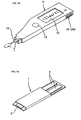
- FIGS. 1A and 1B schematically show a sensor chip 1 and a measuring instrument 11 such as a blood glucose level measuring instrument or the like.
- the sensor chip 1 has a reactive member 2 for reacting with a component such as a blood glucose level or the like and electrode terminals 3.
- the measuring instrument 11 has a sensor chip mount 12 such as a slit or the like for removably mounting the sensor chip 1 therein, a component display unit 13 such as a liquid crystal panel or the like for digitally displaying a component such as a blood glucose level or the like, and a switch 14 such as a switch button or the like.
- the electrode terminals 3 of the sensor chip 1 are removably mounted in the sensor chip mount 12 of the measuring instrument 11.
- the drawn body fluid such as the blood or the like is applied as a dot or drop to the reactive member 2 of the sensor chip 1 mounted in the tip end of the measuring instrument 11.
- the switch 14 is turned on to digitally display the value of a component such as a blood glucose level or the like in the body fluid on the component display unit 13.
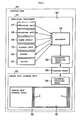
- FIG. 2 is a block diagram showing a general arrangement of the body fluid component analyzing system.
- the body fluid component analyzing system performs an automatic calibrating process automatically in a storage case 31 for correcting performance variations due to different manufacturing lots of sensor chips 1.
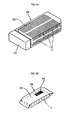
- FIG. 3A shows a sensor chip storage unit 22 which is a container with an openable/closable lid 21 for storing a number of (e.g., 20 to 50) sensor chips 1 of one production lot in a sensor chip storage space 20 formed as an inner space.
- FIG. 3B shows a sensor chip storage unit 24 having a small number of (one to several) sensor chips 1 packaged in a package 23.
- a bar code 44 is used to acquire parameters with an optical parameter transmission arrangement described later on.
- the body fluid component analyzing system shown in FIG. 2 may be implemented with either one of the two sensor chip storage units 22, 24. In this embodiment described below, the sensor chip storage unit 22 is used.
- the storage case 31 has a positioning unit 32 for the measuring instrument 11 and a positioning unit 33 for the sensor chip storage unit 22.
- the two positioning unit 32, 33 are disposed adjacent to each other in the storage case 31.
- the measuring instrument 11 and the sensor chip storage unit 22 are stored and positioned respectively in the positioning units 32, 33.
- a parameter recording means 34 for recording at least one parameter which represents calibrating information (a calibrating coefficient for sensor output, etc.) for correcting variations of the performance of the sensor chips 1 stored in the sensor chip storage unit 22 is applied to or indicated on one of the side faces of the sensor chip storage unit 22.
- a parameter receiving means 35 is applied to a confronting side face of the measuring instrument 11.
- the parameter stored in the parameter recording means is common among the sensor chips stored in the storage case 31. Thus, the parameter is identical in each lot.
- the parameter recording means 34 and the parameter receiving means 35 are brought into contact with each other or closely to each other.
- a transfer means 36 then automatically transfers the at least one parameter of the sensor chips 1 from the parameter recording means 34 of the sensor chip storage unit 22 to the parameter receiving means 35 of the measuring instrument 11, and the transferred parameter is input to a processor 15.
- the processor 15 automatically corrects a performance variation of the sensor chips 1 due to a production lot difference or the like, and stores the corrected performance variation into a memory 16.
- the measuring instrument 11 comprises, in addition to other features, a measuring unit 17, a power supply 18, and a buzzer 19 serving as alarm means.
- the switch 14 is turned on to enable the processor 15 to process characteristics of a component of a body fluid that is measured by the measuring unit 17, store the processed characteristics in the memory 16, and digitally display the processed characteristics on the display unit 13. If a measurement error occurs or the characteristics exceed a reference value, then the processor 15 controls the buzzer 19 to give an alarm.
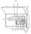
- a body fluid component analyzing system shown in FIG. 4 employs an electric transfer arrangement as the transfer means 36.
- the parameter recording means 34 of the sensor chip storage unit 22 and the parameter receiving means 35 of the measuring instrument 11 include at least a pair of electric contacts 41, 42.
- the positioning units 32, 33, which are cut out along the profiles of the measuring instrument 11 and the sensor chip storage unit 22 respectively are disposed adjacent to each other in the storage case 31.
- An insertion unit 37 for inserting the transfer means 36 therein is formed as a recess in the region across which the positioning units 32, 33 are disposed adjacent to each other.
- a detection switch 43 is disposed on the bottom of the positioning unit 32, for example.
- the detection switch 43 serves as a switch for detecting when the measuring instrument 11 is placed in the storage case 31.
- the detection switch 43 may be any switch such as a mechanical switch, an electrical switch, or the like insofar as it can detect when the measuring instrument 11 is placed in the storage case 31.
- the electric contacts 441, 42 are brought into contact with each other in the insertion unit 37.
- the detection switch 43 detects when the measuring instrument 11 is set in the positioning unit 32, for example. Then, the process of automatically transferring the parameter from the sensor chip storage unit 22 to the measuring instrument 11 is performed.
- the automatic parameter transfer process is performed successively at certain time intervals (e.g., in every hour). According to the present invention, simply when the measuring instrument 11 and the sensor chip storage unit 22 are mounted in the storage case 31, the parameter is thereafter automatically periodically transferred from the sensor chip 22 to the measuring instrument 11.
- the body fluid component analyzing system is convenient to use.
- the automatic parameter transfer may be stopped until the measuring instrument 11 and/or the sensor chip storage unit 22 is removed (the detection switch 43 also detects when the measuring instrument 11 and/or the sensor chip storage unit 22 is removed), thereby simplifying the entire process.
- FIG. 5 shows a body fluid component analyzing system wherein an optical transfer arrangement is employed as the transfer means 36.
- the parameter recording means 34 of the sensor chip storage unit 22 includes optically readable indicating means such as the bar code 44 (see FIG. 3B) or the like.
- the parameter receiving means 35 of the measuring instrument 11 is constructed as light-reflecting reading means including a light-emitting element 45 such as an LED or the like and a light-detecting element 46 such as a phototransistor or the like.
- the bar code 44 is illuminated by the light-emitting element 45 across the insertion unit 37, and reflects light which is detected by the light-detecting element 46.
- the parameter represented by the bar code 44 is automatically transferred from the sensor chip storage unit 22 to the measuring instrument 11 as described above.
- the bar code 44 can be used by the optical transfer arrangement, it is sufficiently possible to employ the sensor chip storage unit 24 which has the small number of (one to several) sensor chips 1 packaged in the package 23, as shown in FIG. 3B, as the sensor chip storage unit.
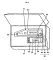
- FIG. 6 shows a body fluid component analyzing system wherein an acoustic transfer arrangement is employed as the transfer means 36.
- the parameter recording means 34 of the sensor chip storage unit 22 includes an acoustic oscillating means 47 which oscillates acoustically.
- the parameter receiving means 35 of the measuring instrument 11 is constructed as an acoustic transmitting and receiving means (e.g., means using a high-frequency wave such as a telephonic pulse or push-tone wave) 48 for transmitting and receiving acoustic energy.
- acoustic transmitting and receiving means e.g., means using a high-frequency wave such as a telephonic pulse or push-tone wave
- the acoustic transmitting and receiving means 48 oscillates a high-frequency wave, and the acoustic oscillating means 47 is vibrated thereby across the insertion unit 37, whereupon the parameter is automatically transferred from the sensor chip storage unit 22 to the measuring instrument 11 in the same manner as described above.
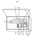
- FIG. 7 shows a body fluid component analyzing system wherein a radio-wave transfer arrangement is employed as the transfer means 36.
- the parameter recording means 34 of the sensor chip storage unit 22 includes a radio-wave transmitting means 49, and the parameter receiving means 35 of the measuring instrument 11 is constructed as a radio-wave transmitting and receiving means 50.
- the radio-wave transmitting and receiving means 49 sends radio-wave information to the radio-wave transmitting and receiving means 50 across the insertion unit 37 due to the reflection of a radio wave transmitted from the radio-wave transmitting and receiving means 50, whereupon the parameter is automatically transferred from the sensor chip storage unit 22 to the measuring instrument 11 in the same manner as described above.
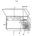
- FIG. 8 shows a body fluid component analyzing system wherein a contactless proximity transfer arrangement is employed as the transfer means 36.
- a storage region 31a which is widely open in the storage case 31 has no positioning units disposed therein for the measuring instrument 11 and the sensor chip storage unit 22. Therefore, the measuring instrument 11 and the sensor chip storage unit 22 are housed in the storage region 31a without being positionally limited.
- a contactless transfer means 51 such as the radio-wave (electromagnetic) transfer arrangement, the acoustic transfer arrangement, or the like as described above is disposed on the bottom of the storage region 31a.
- the parameter of the parameter recording means 34 is read by the contactless transfer means 51, and automatically transferred to the parameter receiving means 35 of the measuring instrument 11.
- the measuring instrument 11 and the sensor chip storage unit 22 are not required to be positioned at particular places, but may be moved within the storage case 31, as indicated by the arrows A, B.
- both the measuring instrument 11 and the sensor chip storage unit 22 as they are placed in the storage case 31 have to be detected by something like the detection switch 43, if the detection switch 43 includes a contact-type switch, then it is desirable that either one of the measuring instrument 11 and the sensor chip storage unit 22 be disposed for contact with the detection switch 43.
- FIG. 9 shows a body fluid component analyzing system wherein an indirect transfer arrangement is employed which uses the storage case 31 as a medium.
- a transmitter 53 and a receiver 54 of an indirect transfer means 52 such as the electric transfer arrangement, the optical transfer arrangement, the acoustic transfer arrangement, the radio-wave (electromagnetic) transfer arrangement, or the like as described above are disposed on the bottoms of the positioning units 32, 33 of the measuring instrument 11 and the sensor chip storage unit 22 in the storage case 31.
- the parameter recording means 34 disposed on the bottoms of the sensor chip storage unit 22 and the measuring instrument 11 contact or approach the transmitter 53 and the receiver 54 of the indirect transfer means 52.
- the parameter of the parameter recording means 34 of the sensor chip storage unit 22 is read by the transmitter 53, and transferred by the indirect transfer means 52 to the parameter receiving means 35 of the measuring instrument 11 through the receiver 54.
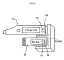
- FIG. 10 shows a transfer function section detached from the indirect transfer arrangement according to the embodiment shown in FIG. 9.
- the transfer means of the indirect transfer arrangement is detachable from the storage case. This structure allows the parameter to be calibrated outside of the storage case.
- both the measuring instrument 11 and the sensor chip storage unit are stored in the storage case 31 for automatically transferring the parameter.
- only the measuring instrument 11 may be stored (set) in the storage case, and the sensor chip storage unit 22 may be brought close to the storage case to automatically transfer the parameter from the sensor chip storage unit 22 to the measuring instrument 11.
- the body fluid component analyzing system thus constructed according to the present invention is capable of automatically transferring the parameter from the sensor chip to the measuring instrument, the parameter can automatically be calibrated when the lot for the parameter is changed without the need for the user to replace a memory key or to load the parameter into the measuring instrument each time the lot for the parameter is changed.
- the diabetic patient can measure a blood glucose level at ease.
- the user Since the user is not required to be conscious, the user can use the body fluid component analyzing system in substantially the same manner as when no parameter is calibrated, so that the diabetic patient is less troubled by the use of the system.
Landscapes
- Health & Medical Sciences (AREA)
- Engineering & Computer Science (AREA)
- Life Sciences & Earth Sciences (AREA)
- Biomedical Technology (AREA)
- Physics & Mathematics (AREA)
- Chemical & Material Sciences (AREA)
- Biochemistry (AREA)
- General Health & Medical Sciences (AREA)
- Molecular Biology (AREA)
- Urology & Nephrology (AREA)
- Optics & Photonics (AREA)
- Food Science & Technology (AREA)
- Medicinal Chemistry (AREA)
- Analytical Chemistry (AREA)
- Hematology (AREA)
- General Physics & Mathematics (AREA)
- Biophysics (AREA)
- Immunology (AREA)
- Pathology (AREA)
- Measurement Of The Respiration, Hearing Ability, Form, And Blood Characteristics Of Living Organisms (AREA)
- Investigating Or Analysing Biological Materials (AREA)
- Sampling And Sample Adjustment (AREA)
- Automatic Analysis And Handling Materials Therefor (AREA)
Abstract
Description
Claims (11)
- A body fluid component analyzing system comprising:a sensor chip for detecting characteristics of at least one component of a body fluid;a measuring instrument having processing means, to which said sensor chip is adapted to be connected, for processing the characteristics of said component;a sensor chip storage unit for storing or packaging at least one said sensor chip;a storage case for storing at least said measuring instrument;parameter recording means applied to or indicated on said sensor chip storage unit, for recording at least one parameter used when said processing means of said measuring instrument processes the characteristics;parameter receiving means provided in said measuring instrument, for receiving said parameter recorded at said parameter recording means; andtransfer means for transferring said parameter recorded at said parameter recording means to said parameter receiving means of said measuring instrument while at least said measuring instrument is stored in said storage case.
- A body fluid component analyzing system comprising:a sensor chip for detecting characteristics of at least one component of a body fluid;a measuring instrument having processing means, to which said sensor chip is adapted to be connected for processing the characteristics of said component;a sensor chip storage unit for storing or packaging at least one said sensor chip;a storage case for storing said measuring instrument and said sensor chip storage unit;parameter recording means applied to or indicated on said sensor chip storage unit, for recording at least one parameter used when said processing means of said measuring instrument processes the characteristics;parameter receiving means disposed in said measuring instrument, for receiving said parameter recorded at said parameter recording means; andtransfer means disposed in said storage case, for reading and transferring said parameter recorded at said parameter recording means to said parameter receiving means disposed in said measuring instrument while said measuring instrument and said sensor chip storage unit are stored in said storage case.
- A body fluid component analyzing system according to claim 2, wherein said transfer means is detachably disposed in said storage case.
- A body fluid component analyzing system according to claim 1 or 2, wherein said parameter represents calibrating information for correcting variations of the performance of said sensor chip.
- A body fluid component analyzing system according to claim 1 or 2, wherein said transfer means transfers said parameter while said measuring instrument and said sensor chip storage unit are being positioned in said storage case.
- A body fluid component analyzing system according to claim 1 or 2, wherein said transfer means comprises an electric transfer arrangement for transferring said parameter between said parameter recording means and said parameter receiving means through electric contacts.
- A body fluid component analyzing system according to claim 1 or 2, wherein said transfer means comprises an optical transfer arrangement for optically transferring said parameter between said parameter recording means and said parameter receiving means.
- A body fluid component analyzing system according to claim 7, wherein the parameter transferred from said parameter recording means to said parameter receiving means by said optical transfer arrangement comprises optical information represented by a bar code.
- A body fluid component analyzing system according to claim 1 or 2, wherein said transfer means comprises an acoustic transfer arrangement for acoustically transferring said parameter between said parameter recording means and said parameter receiving means.
- A body fluid component analyzing system according to claim 1 or 2, wherein said transfer means comprises a radio-wave transfer arrangement for transferring said parameter between said parameter recording means and said parameter receiving means by way of a radio wave.
- A body fluid component analyzing system according to claim 1 or 2, wherein said transfer means comprises an electromagnetic transfer arrangement for electromagnetically transferring said parameter between said parameter recording means and said parameter receiving means.
Applications Claiming Priority (3)
| Application Number | Priority Date | Filing Date | Title |
|---|---|---|---|
| JP2003016997 | 2003-01-27 | ||
| JP2003016997 | 2003-01-27 | ||
| PCT/JP2004/000580 WO2004068128A1 (en) | 2003-01-27 | 2004-01-23 | Body fluid component analyzing system |
Publications (3)
| Publication Number | Publication Date |
|---|---|
| EP1589334A1 true EP1589334A1 (en) | 2005-10-26 |
| EP1589334A4 EP1589334A4 (en) | 2010-07-21 |
| EP1589334B1 EP1589334B1 (en) | 2014-01-22 |
Family
ID=32820550
Family Applications (1)
| Application Number | Title | Priority Date | Filing Date |
|---|---|---|---|
| EP04704724.6A Expired - Lifetime EP1589334B1 (en) | 2003-01-27 | 2004-01-23 | Body fluid component analyzing system |
Country Status (5)
| Country | Link |
|---|---|
| US (1) | US7481976B2 (en) |
| EP (1) | EP1589334B1 (en) |
| JP (1) | JP4405967B2 (en) |
| CN (1) | CN100401049C (en) |
| WO (1) | WO2004068128A1 (en) |
Families Citing this family (64)
| Publication number | Priority date | Publication date | Assignee | Title |
|---|---|---|---|---|
| US6036924A (en) | 1997-12-04 | 2000-03-14 | Hewlett-Packard Company | Cassette of lancet cartridges for sampling blood |
| US6391005B1 (en) | 1998-03-30 | 2002-05-21 | Agilent Technologies, Inc. | Apparatus and method for penetration with shaft having a sensor for sensing penetration depth |
| DE10057832C1 (en) | 2000-11-21 | 2002-02-21 | Hartmann Paul Ag | Blood analysis device has syringe mounted in casing, annular mounting carrying needles mounted behind test strip and being swiveled so that needle can be pushed through strip and aperture in casing to take blood sample |
| US7981056B2 (en) | 2002-04-19 | 2011-07-19 | Pelikan Technologies, Inc. | Methods and apparatus for lancet actuation |
| US9226699B2 (en) | 2002-04-19 | 2016-01-05 | Sanofi-Aventis Deutschland Gmbh | Body fluid sampling module with a continuous compression tissue interface surface |
| AU2002348683A1 (en) | 2001-06-12 | 2002-12-23 | Pelikan Technologies, Inc. | Method and apparatus for lancet launching device integrated onto a blood-sampling cartridge |
| EP1404232B1 (en) | 2001-06-12 | 2009-12-02 | Pelikan Technologies Inc. | Blood sampling apparatus and method |
| DE60239132D1 (en) | 2001-06-12 | 2011-03-24 | Pelikan Technologies Inc | APPARATUS FOR INCREASING THE SUCCESS RATE IN RESPECT OF BLOOD EXPLOITATION OBTAINED BY A FINGERSTICK |
| JP4209767B2 (en) | 2001-06-12 | 2009-01-14 | ペリカン テクノロジーズ インコーポレイテッド | Self-optimized cutting instrument with adaptive means for temporary changes in skin properties |
| ATE494837T1 (en) | 2001-06-12 | 2011-01-15 | Pelikan Technologies Inc | INTEGRATED SYSTEM FOR BLOOD SAMPLE ANALYSIS WITH MULTIPLE-USE SAMPLING MODULE |
| US8337419B2 (en) | 2002-04-19 | 2012-12-25 | Sanofi-Aventis Deutschland Gmbh | Tissue penetration device |
| US9795747B2 (en) | 2010-06-02 | 2017-10-24 | Sanofi-Aventis Deutschland Gmbh | Methods and apparatus for lancet actuation |
| US7025774B2 (en) | 2001-06-12 | 2006-04-11 | Pelikan Technologies, Inc. | Tissue penetration device |
| ATE485766T1 (en) | 2001-06-12 | 2010-11-15 | Pelikan Technologies Inc | ELECTRICAL ACTUATING ELEMENT FOR A LANCET |
| US7410468B2 (en) | 2002-04-19 | 2008-08-12 | Pelikan Technologies, Inc. | Method and apparatus for penetrating tissue |
| US7491178B2 (en) | 2002-04-19 | 2009-02-17 | Pelikan Technologies, Inc. | Method and apparatus for penetrating tissue |
| US7909778B2 (en) | 2002-04-19 | 2011-03-22 | Pelikan Technologies, Inc. | Method and apparatus for penetrating tissue |
| US7141058B2 (en) | 2002-04-19 | 2006-11-28 | Pelikan Technologies, Inc. | Method and apparatus for a body fluid sampling device using illumination |
| US8267870B2 (en) | 2002-04-19 | 2012-09-18 | Sanofi-Aventis Deutschland Gmbh | Method and apparatus for body fluid sampling with hybrid actuation |
| US7524293B2 (en) | 2002-04-19 | 2009-04-28 | Pelikan Technologies, Inc. | Method and apparatus for penetrating tissue |
| US7717863B2 (en) | 2002-04-19 | 2010-05-18 | Pelikan Technologies, Inc. | Method and apparatus for penetrating tissue |
| US7674232B2 (en) | 2002-04-19 | 2010-03-09 | Pelikan Technologies, Inc. | Method and apparatus for penetrating tissue |
| US7648468B2 (en) | 2002-04-19 | 2010-01-19 | Pelikon Technologies, Inc. | Method and apparatus for penetrating tissue |
| US7901362B2 (en) | 2002-04-19 | 2011-03-08 | Pelikan Technologies, Inc. | Method and apparatus for penetrating tissue |
| US8221334B2 (en) | 2002-04-19 | 2012-07-17 | Sanofi-Aventis Deutschland Gmbh | Method and apparatus for penetrating tissue |
| US7547287B2 (en) | 2002-04-19 | 2009-06-16 | Pelikan Technologies, Inc. | Method and apparatus for penetrating tissue |
| US7297122B2 (en) | 2002-04-19 | 2007-11-20 | Pelikan Technologies, Inc. | Method and apparatus for penetrating tissue |
| US8579831B2 (en) | 2002-04-19 | 2013-11-12 | Sanofi-Aventis Deutschland Gmbh | Method and apparatus for penetrating tissue |
| US7582099B2 (en) | 2002-04-19 | 2009-09-01 | Pelikan Technologies, Inc | Method and apparatus for penetrating tissue |
| US7232451B2 (en) | 2002-04-19 | 2007-06-19 | Pelikan Technologies, Inc. | Method and apparatus for penetrating tissue |
| US7563232B2 (en) | 2002-04-19 | 2009-07-21 | Pelikan Technologies, Inc. | Method and apparatus for penetrating tissue |
| US9795334B2 (en) | 2002-04-19 | 2017-10-24 | Sanofi-Aventis Deutschland Gmbh | Method and apparatus for penetrating tissue |
| US7713214B2 (en) | 2002-04-19 | 2010-05-11 | Pelikan Technologies, Inc. | Method and apparatus for a multi-use body fluid sampling device with optical analyte sensing |
| US8702624B2 (en) | 2006-09-29 | 2014-04-22 | Sanofi-Aventis Deutschland Gmbh | Analyte measurement device with a single shot actuator |
| US7371247B2 (en) | 2002-04-19 | 2008-05-13 | Pelikan Technologies, Inc | Method and apparatus for penetrating tissue |
| US7175642B2 (en) | 2002-04-19 | 2007-02-13 | Pelikan Technologies, Inc. | Methods and apparatus for lancet actuation |
| US7976476B2 (en) | 2002-04-19 | 2011-07-12 | Pelikan Technologies, Inc. | Device and method for variable speed lancet |
| US7331931B2 (en) | 2002-04-19 | 2008-02-19 | Pelikan Technologies, Inc. | Method and apparatus for penetrating tissue |
| US9314194B2 (en) | 2002-04-19 | 2016-04-19 | Sanofi-Aventis Deutschland Gmbh | Tissue penetration device |
| US7229458B2 (en) | 2002-04-19 | 2007-06-12 | Pelikan Technologies, Inc. | Method and apparatus for penetrating tissue |
| US8574895B2 (en) | 2002-12-30 | 2013-11-05 | Sanofi-Aventis Deutschland Gmbh | Method and apparatus using optical techniques to measure analyte levels |
| ES2490740T3 (en) | 2003-06-06 | 2014-09-04 | Sanofi-Aventis Deutschland Gmbh | Apparatus for blood fluid sampling and analyte detection |
| WO2006001797A1 (en) | 2004-06-14 | 2006-01-05 | Pelikan Technologies, Inc. | Low pain penetrating |
| EP1671096A4 (en) | 2003-09-29 | 2009-09-16 | Pelikan Technologies Inc | METHOD AND APPARATUS FOR AN IMPROVED SAMPLING INTERFERENCE DEVICE |
| WO2005037095A1 (en) | 2003-10-14 | 2005-04-28 | Pelikan Technologies, Inc. | Method and apparatus for a variable user interface |
| US8668656B2 (en) | 2003-12-31 | 2014-03-11 | Sanofi-Aventis Deutschland Gmbh | Method and apparatus for improving fluidic flow and sample capture |
| US7822454B1 (en) | 2005-01-03 | 2010-10-26 | Pelikan Technologies, Inc. | Fluid sampling device with improved analyte detecting member configuration |
| US8828203B2 (en) | 2004-05-20 | 2014-09-09 | Sanofi-Aventis Deutschland Gmbh | Printable hydrogels for biosensors |
| MX2007002225A (en) * | 2004-08-24 | 2007-05-04 | Bayer Healthcare Llc | An instrument with a memory card updating measurement algorithms and methods of using the same. |
| DE102004062255B3 (en) * | 2004-12-23 | 2006-02-16 | Roche Diagnostics Gmbh | Portable process and assembly to determine and record blood sugar level for diabetics has test strip container with hinge flip electronic counter |
| US8652831B2 (en) | 2004-12-30 | 2014-02-18 | Sanofi-Aventis Deutschland Gmbh | Method and apparatus for analyte measurement test time |
| US7545272B2 (en) | 2005-02-08 | 2009-06-09 | Therasense, Inc. | RF tag on test strips, test strip vials and boxes |
| WO2006131697A2 (en) * | 2005-06-10 | 2006-12-14 | Hypoguard Limited | Test system |
| CN101051045A (en) * | 2006-02-24 | 2007-10-10 | 生命扫描苏格兰有限公司 | Usability methods of calibrating an analyte measurement meter using RFID |
| US20080274552A1 (en) * | 2007-05-04 | 2008-11-06 | Brian Guthrie | Dynamic Information Transfer |
| US9386944B2 (en) | 2008-04-11 | 2016-07-12 | Sanofi-Aventis Deutschland Gmbh | Method and apparatus for analyte detecting device |
| US8647575B2 (en) * | 2008-11-21 | 2014-02-11 | Terumo Kabushiki Kaisha | Device for measuring blood component |
| KR101689890B1 (en) * | 2009-10-26 | 2016-12-26 | 아크레이 인코퍼레이티드 | Sensor cartridge and measuring device |
| US8965476B2 (en) | 2010-04-16 | 2015-02-24 | Sanofi-Aventis Deutschland Gmbh | Tissue penetration device |
| JP5516289B2 (en) * | 2010-09-30 | 2014-06-11 | 大日本印刷株式会社 | Glucose concentration measuring device system, glucose sensor chip carrying case |
| CN103958376A (en) * | 2011-04-08 | 2014-07-30 | Csp技术公司 | Strip Dispenser and Strips Used With It |
| WO2014115664A1 (en) * | 2013-01-23 | 2014-07-31 | テルモ株式会社 | Calibration method, device, and program, and bodily-fluid component measurement device calibrated using said method |
| JP2014081389A (en) * | 2014-02-10 | 2014-05-08 | Dainippon Printing Co Ltd | Glucose concentration measuring apparatus system and glucose concentration measuring meter |
| WO2016149840A1 (en) * | 2015-03-20 | 2016-09-29 | Uster Technologies Ag | Modular thread testing device |
Family Cites Families (19)
| Publication number | Priority date | Publication date | Assignee | Title |
|---|---|---|---|---|
| CA1226036A (en) | 1983-05-05 | 1987-08-25 | Irving J. Higgins | Analytical equipment and sensor electrodes therefor |
| US4935346A (en) | 1986-08-13 | 1990-06-19 | Lifescan, Inc. | Minimum procedure system for the determination of analytes |
| JP2903273B2 (en) * | 1992-04-20 | 1999-06-07 | 富士写真フイルム株式会社 | Method for transporting dry analytical film pieces and cartridge |
| JP2541081B2 (en) * | 1992-08-28 | 1996-10-09 | 日本電気株式会社 | Biosensor and method of manufacturing and using biosensor |
| EP1130383B1 (en) * | 1993-04-23 | 2004-09-15 | Roche Diagnostics GmbH | Diskette with circular arranged test elements |
| US5366609A (en) | 1993-06-08 | 1994-11-22 | Boehringer Mannheim Corporation | Biosensing meter with pluggable memory key |
| DE4321548A1 (en) | 1993-06-29 | 1995-01-12 | Boehringer Mannheim Gmbh | Method for acquiring and evaluating analog photometric signals in a test carrier analysis system and arrangement for carrying out the method |
| DE4328815A1 (en) * | 1993-08-27 | 1995-03-02 | Boehringer Mannheim Gmbh | System for the storage of test elements |
| JPH08114603A (en) * | 1994-10-17 | 1996-05-07 | Fuji Photo Film Co Ltd | Dry analytical film cartridge and film take-out device |
| US5989917A (en) * | 1996-02-13 | 1999-11-23 | Selfcare, Inc. | Glucose monitor and test strip containers for use in same |
| JPH09250998A (en) | 1996-03-14 | 1997-09-22 | Daikin Ind Ltd | Concentration measuring device |
| US5736103A (en) * | 1996-08-09 | 1998-04-07 | Lifescan, Inc. | Remote-dosing analyte concentration meter |
| EP1258728B1 (en) | 1996-10-30 | 2012-05-30 | F. Hoffmann-La Roche AG | Synchronized analyte testing system |
| GB9708585D0 (en) * | 1997-04-29 | 1997-06-18 | Eastman Kodak Co | Apparatus, magazine and method for electrochemical detection or measurement |
| US6602469B1 (en) * | 1998-11-09 | 2003-08-05 | Lifestream Technologies, Inc. | Health monitoring and diagnostic device and network-based health assessment and medical records maintenance system |
| IL143059A0 (en) * | 1998-11-09 | 2002-04-21 | Lifestream Technologies Inc | Health monitoring and diagnostic device and network-based health assessment and medical records maintenance system |
| CA2365609A1 (en) * | 1999-02-12 | 2000-08-17 | Cygnus, Inc. | Devices and methods for frequent measurement of an analyte present in a biological system |
| JP4471425B2 (en) * | 1999-11-18 | 2010-06-02 | パナソニック株式会社 | Sensor supply device |
| CN2528010Y (en) * | 2002-04-02 | 2002-12-25 | 泰博科技股份有限公司 | biosensor device |
-
2004
- 2004-01-23 EP EP04704724.6A patent/EP1589334B1/en not_active Expired - Lifetime
- 2004-01-23 CN CNB2004800015622A patent/CN100401049C/en not_active Expired - Lifetime
- 2004-01-23 WO PCT/JP2004/000580 patent/WO2004068128A1/en not_active Ceased
- 2004-01-23 US US10/543,498 patent/US7481976B2/en not_active Expired - Lifetime
- 2004-01-23 JP JP2005504686A patent/JP4405967B2/en not_active Expired - Fee Related
Also Published As
| Publication number | Publication date |
|---|---|
| EP1589334B1 (en) | 2014-01-22 |
| JP4405967B2 (en) | 2010-01-27 |
| HK1084730A1 (en) | 2006-08-04 |
| EP1589334A4 (en) | 2010-07-21 |
| CN100401049C (en) | 2008-07-09 |
| US7481976B2 (en) | 2009-01-27 |
| CN1717583A (en) | 2006-01-04 |
| US20060151342A1 (en) | 2006-07-13 |
| WO2004068128A1 (en) | 2004-08-12 |
| JPWO2004068128A1 (en) | 2006-05-25 |
Similar Documents
| Publication | Publication Date | Title |
|---|---|---|
| US7481976B2 (en) | Body fluid component analyzing system | |
| US8721544B2 (en) | System for in-vivo measurement of an analyte concentration | |
| US5507288A (en) | Analytical system for monitoring a substance to be analyzed in patient-blood | |
| US7998407B2 (en) | Measurement system for measuring substance concentrations in liquid media | |
| EP0199484B1 (en) | Medical system | |
| US10238289B2 (en) | Body fluid component measuring system | |
| EP0449525A1 (en) | Medical diagnostic system | |
| US20150286851A1 (en) | Analyte Meter Including an RFID Reader | |
| JP2001017404A (en) | Medical measuring device | |
| JP2012132938A (en) | Test system | |
| KR20070088406A (en) | Usability method to calibrate analyte meter using RFID | |
| WO2011033875A1 (en) | Blood glucose meter | |
| JP5516289B2 (en) | Glucose concentration measuring device system, glucose sensor chip carrying case | |
| HK1084730B (en) | Body fluid component analyzing system | |
| JP5977121B2 (en) | Measuring system | |
| JP2008241410A (en) | Biochemical measuring instrument stand that can display the status of the biochemical measuring instrument | |
| JP2883723B2 (en) | Portable blood glucose measurement system | |
| JP4445276B2 (en) | Blood glucose measuring device | |
| HK40077079A (en) | Wearable devices, wearable device forming methods, and methods of reuse of transmitter units of wearable devices in continuous analyte monitoring systems |
Legal Events
| Date | Code | Title | Description |
|---|---|---|---|
| PUAI | Public reference made under article 153(3) epc to a published international application that has entered the european phase |
Free format text: ORIGINAL CODE: 0009012 |
|
| 17P | Request for examination filed |
Effective date: 20050829 |
|
| AK | Designated contracting states |
Kind code of ref document: A1 Designated state(s): AT BE BG CH CY CZ DE DK EE ES FI FR GB GR HU IE IT LI LU MC NL PT RO SE SI SK TR |
|
| AX | Request for extension of the european patent |
Extension state: AL LT LV MK |
|
| DAX | Request for extension of the european patent (deleted) | ||
| A4 | Supplementary search report drawn up and despatched |
Effective date: 20100617 |
|
| RIC1 | Information provided on ipc code assigned before grant |
Ipc: G01N 27/327 20060101ALI20100611BHEP Ipc: G01N 33/66 20060101ALI20100611BHEP Ipc: G01N 27/416 20060101ALI20100611BHEP Ipc: G01N 27/28 20060101ALI20100611BHEP Ipc: G01N 33/487 20060101AFI20100611BHEP |
|
| 17Q | First examination report despatched |
Effective date: 20110711 |
|
| REG | Reference to a national code |
Ref country code: DE Ref legal event code: R079 Ref document number: 602004044306 Country of ref document: DE Free format text: PREVIOUS MAIN CLASS: G01N0027280000 Ipc: G01N0033487000 |
|
| GRAP | Despatch of communication of intention to grant a patent |
Free format text: ORIGINAL CODE: EPIDOSNIGR1 |
|
| RIC1 | Information provided on ipc code assigned before grant |
Ipc: G01N 33/487 20060101AFI20130722BHEP Ipc: G01N 27/28 20060101ALI20130722BHEP Ipc: G01N 27/416 20060101ALI20130722BHEP Ipc: G01N 27/327 20060101ALI20130722BHEP Ipc: G01N 33/66 20060101ALI20130722BHEP |
|
| INTG | Intention to grant announced |
Effective date: 20130813 |
|
| GRAS | Grant fee paid |
Free format text: ORIGINAL CODE: EPIDOSNIGR3 |
|
| GRAA | (expected) grant |
Free format text: ORIGINAL CODE: 0009210 |
|
| RIN1 | Information on inventor provided before grant (corrected) |
Inventor name: YAGUCHI, YOSHIAKI |
|
| AK | Designated contracting states |
Kind code of ref document: B1 Designated state(s): AT BE BG CH CY CZ DE DK EE ES FI FR GB GR HU IE IT LI LU MC NL PT RO SE SI SK TR |
|
| REG | Reference to a national code |
Ref country code: GB Ref legal event code: FG4D |
|
| REG | Reference to a national code |
Ref country code: CH Ref legal event code: EP |
|
| REG | Reference to a national code |
Ref country code: AT Ref legal event code: REF Ref document number: 651026 Country of ref document: AT Kind code of ref document: T Effective date: 20140215 |
|
| REG | Reference to a national code |
Ref country code: IE Ref legal event code: FG4D |
|
| REG | Reference to a national code |
Ref country code: DE Ref legal event code: R096 Ref document number: 602004044306 Country of ref document: DE Effective date: 20140227 |
|
| PGFP | Annual fee paid to national office [announced via postgrant information from national office to epo] |
Ref country code: DE Payment date: 20140325 Year of fee payment: 11 |
|
| REG | Reference to a national code |
Ref country code: NL Ref legal event code: VDEP Effective date: 20140122 |
|
| REG | Reference to a national code |
Ref country code: AT Ref legal event code: MK05 Ref document number: 651026 Country of ref document: AT Kind code of ref document: T Effective date: 20140122 |
|
| PGFP | Annual fee paid to national office [announced via postgrant information from national office to epo] |
Ref country code: GB Payment date: 20140206 Year of fee payment: 11 |
|
| PG25 | Lapsed in a contracting state [announced via postgrant information from national office to epo] |
Ref country code: SE Free format text: LAPSE BECAUSE OF FAILURE TO SUBMIT A TRANSLATION OF THE DESCRIPTION OR TO PAY THE FEE WITHIN THE PRESCRIBED TIME-LIMIT Effective date: 20140122 Ref country code: CY Free format text: LAPSE BECAUSE OF FAILURE TO SUBMIT A TRANSLATION OF THE DESCRIPTION OR TO PAY THE FEE WITHIN THE PRESCRIBED TIME-LIMIT Effective date: 20140122 Ref country code: ES Free format text: LAPSE BECAUSE OF FAILURE TO SUBMIT A TRANSLATION OF THE DESCRIPTION OR TO PAY THE FEE WITHIN THE PRESCRIBED TIME-LIMIT Effective date: 20140122 Ref country code: AT Free format text: LAPSE BECAUSE OF FAILURE TO SUBMIT A TRANSLATION OF THE DESCRIPTION OR TO PAY THE FEE WITHIN THE PRESCRIBED TIME-LIMIT Effective date: 20140122 Ref country code: NL Free format text: LAPSE BECAUSE OF FAILURE TO SUBMIT A TRANSLATION OF THE DESCRIPTION OR TO PAY THE FEE WITHIN THE PRESCRIBED TIME-LIMIT Effective date: 20140122 Ref country code: PT Free format text: LAPSE BECAUSE OF FAILURE TO SUBMIT A TRANSLATION OF THE DESCRIPTION OR TO PAY THE FEE WITHIN THE PRESCRIBED TIME-LIMIT Effective date: 20140522 Ref country code: FI Free format text: LAPSE BECAUSE OF FAILURE TO SUBMIT A TRANSLATION OF THE DESCRIPTION OR TO PAY THE FEE WITHIN THE PRESCRIBED TIME-LIMIT Effective date: 20140122 |
|
| REG | Reference to a national code |
Ref country code: CH Ref legal event code: PL |
|
| PG25 | Lapsed in a contracting state [announced via postgrant information from national office to epo] |
Ref country code: BE Free format text: LAPSE BECAUSE OF FAILURE TO SUBMIT A TRANSLATION OF THE DESCRIPTION OR TO PAY THE FEE WITHIN THE PRESCRIBED TIME-LIMIT Effective date: 20140122 |
|
| REG | Reference to a national code |
Ref country code: DE Ref legal event code: R097 Ref document number: 602004044306 Country of ref document: DE |
|
| PG25 | Lapsed in a contracting state [announced via postgrant information from national office to epo] |
Ref country code: CZ Free format text: LAPSE BECAUSE OF FAILURE TO SUBMIT A TRANSLATION OF THE DESCRIPTION OR TO PAY THE FEE WITHIN THE PRESCRIBED TIME-LIMIT Effective date: 20140122 Ref country code: CH Free format text: LAPSE BECAUSE OF NON-PAYMENT OF DUE FEES Effective date: 20140131 Ref country code: EE Free format text: LAPSE BECAUSE OF FAILURE TO SUBMIT A TRANSLATION OF THE DESCRIPTION OR TO PAY THE FEE WITHIN THE PRESCRIBED TIME-LIMIT Effective date: 20140122 Ref country code: RO Free format text: LAPSE BECAUSE OF FAILURE TO SUBMIT A TRANSLATION OF THE DESCRIPTION OR TO PAY THE FEE WITHIN THE PRESCRIBED TIME-LIMIT Effective date: 20140122 Ref country code: LI Free format text: LAPSE BECAUSE OF NON-PAYMENT OF DUE FEES Effective date: 20140131 Ref country code: DK Free format text: LAPSE BECAUSE OF FAILURE TO SUBMIT A TRANSLATION OF THE DESCRIPTION OR TO PAY THE FEE WITHIN THE PRESCRIBED TIME-LIMIT Effective date: 20140122 Ref country code: MC Free format text: LAPSE BECAUSE OF FAILURE TO SUBMIT A TRANSLATION OF THE DESCRIPTION OR TO PAY THE FEE WITHIN THE PRESCRIBED TIME-LIMIT Effective date: 20140122 |
|
| REG | Reference to a national code |
Ref country code: IE Ref legal event code: MM4A |
|
| PG25 | Lapsed in a contracting state [announced via postgrant information from national office to epo] |
Ref country code: SK Free format text: LAPSE BECAUSE OF FAILURE TO SUBMIT A TRANSLATION OF THE DESCRIPTION OR TO PAY THE FEE WITHIN THE PRESCRIBED TIME-LIMIT Effective date: 20140122 |
|
| PLBE | No opposition filed within time limit |
Free format text: ORIGINAL CODE: 0009261 |
|
| STAA | Information on the status of an ep patent application or granted ep patent |
Free format text: STATUS: NO OPPOSITION FILED WITHIN TIME LIMIT |
|
| 26N | No opposition filed |
Effective date: 20141023 |
|
| REG | Reference to a national code |
Ref country code: FR Ref legal event code: ST Effective date: 20141208 |
|
| PG25 | Lapsed in a contracting state [announced via postgrant information from national office to epo] |
Ref country code: FR Free format text: LAPSE BECAUSE OF NON-PAYMENT OF DUE FEES Effective date: 20140324 Ref country code: IE Free format text: LAPSE BECAUSE OF NON-PAYMENT OF DUE FEES Effective date: 20140123 |
|
| REG | Reference to a national code |
Ref country code: DE Ref legal event code: R097 Ref document number: 602004044306 Country of ref document: DE Effective date: 20141023 |
|
| PG25 | Lapsed in a contracting state [announced via postgrant information from national office to epo] |
Ref country code: SI Free format text: LAPSE BECAUSE OF FAILURE TO SUBMIT A TRANSLATION OF THE DESCRIPTION OR TO PAY THE FEE WITHIN THE PRESCRIBED TIME-LIMIT Effective date: 20140122 |
|
| REG | Reference to a national code |
Ref country code: DE Ref legal event code: R119 Ref document number: 602004044306 Country of ref document: DE |
|
| GBPC | Gb: european patent ceased through non-payment of renewal fee |
Effective date: 20150123 |
|
| PG25 | Lapsed in a contracting state [announced via postgrant information from national office to epo] |
Ref country code: DE Free format text: LAPSE BECAUSE OF NON-PAYMENT OF DUE FEES Effective date: 20150801 Ref country code: GB Free format text: LAPSE BECAUSE OF NON-PAYMENT OF DUE FEES Effective date: 20150123 |
|
| PG25 | Lapsed in a contracting state [announced via postgrant information from national office to epo] |
Ref country code: BG Free format text: LAPSE BECAUSE OF FAILURE TO SUBMIT A TRANSLATION OF THE DESCRIPTION OR TO PAY THE FEE WITHIN THE PRESCRIBED TIME-LIMIT Effective date: 20140122 |
|
| PG25 | Lapsed in a contracting state [announced via postgrant information from national office to epo] |
Ref country code: IT Free format text: LAPSE BECAUSE OF FAILURE TO SUBMIT A TRANSLATION OF THE DESCRIPTION OR TO PAY THE FEE WITHIN THE PRESCRIBED TIME-LIMIT Effective date: 20140122 Ref country code: GR Free format text: LAPSE BECAUSE OF FAILURE TO SUBMIT A TRANSLATION OF THE DESCRIPTION OR TO PAY THE FEE WITHIN THE PRESCRIBED TIME-LIMIT Effective date: 20140423 |
|
| PG25 | Lapsed in a contracting state [announced via postgrant information from national office to epo] |
Ref country code: LU Free format text: LAPSE BECAUSE OF NON-PAYMENT OF DUE FEES Effective date: 20140123 Ref country code: TR Free format text: LAPSE BECAUSE OF FAILURE TO SUBMIT A TRANSLATION OF THE DESCRIPTION OR TO PAY THE FEE WITHIN THE PRESCRIBED TIME-LIMIT Effective date: 20140122 Ref country code: HU Free format text: LAPSE BECAUSE OF FAILURE TO SUBMIT A TRANSLATION OF THE DESCRIPTION OR TO PAY THE FEE WITHIN THE PRESCRIBED TIME-LIMIT; INVALID AB INITIO Effective date: 20040123 |