EP1589330A1 - Audio packet vanishment concealing device, audio packet vanishment concealing method, reception terminal, and audio communication system - Google Patents
Audio packet vanishment concealing device, audio packet vanishment concealing method, reception terminal, and audio communication system Download PDFInfo
- Publication number
- EP1589330A1 EP1589330A1 EP03815584A EP03815584A EP1589330A1 EP 1589330 A1 EP1589330 A1 EP 1589330A1 EP 03815584 A EP03815584 A EP 03815584A EP 03815584 A EP03815584 A EP 03815584A EP 1589330 A1 EP1589330 A1 EP 1589330A1
- Authority
- EP
- European Patent Office
- Prior art keywords
- voice
- packet
- loss
- pitch
- section
- Prior art date
- Legal status (The legal status is an assumption and is not a legal conclusion. Google has not performed a legal analysis and makes no representation as to the accuracy of the status listed.)
- Granted
Links
Images


Classifications
-
- G—PHYSICS
- G10—MUSICAL INSTRUMENTS; ACOUSTICS
- G10L—SPEECH ANALYSIS OR SYNTHESIS; SPEECH RECOGNITION; SPEECH OR VOICE PROCESSING; SPEECH OR AUDIO CODING OR DECODING
- G10L19/00—Speech or audio signals analysis-synthesis techniques for redundancy reduction, e.g. in vocoders; Coding or decoding of speech or audio signals, using source filter models or psychoacoustic analysis
- G10L19/005—Correction of errors induced by the transmission channel, if related to the coding algorithm
-
- H—ELECTRICITY
- H04—ELECTRIC COMMUNICATION TECHNIQUE
- H04L—TRANSMISSION OF DIGITAL INFORMATION, e.g. TELEGRAPHIC COMMUNICATION
- H04L65/00—Network arrangements, protocols or services for supporting real-time applications in data packet communication
- H04L65/1066—Session management
- H04L65/1101—Session protocols
-
- H—ELECTRICITY
- H04—ELECTRIC COMMUNICATION TECHNIQUE
- H04L—TRANSMISSION OF DIGITAL INFORMATION, e.g. TELEGRAPHIC COMMUNICATION
- H04L65/00—Network arrangements, protocols or services for supporting real-time applications in data packet communication
- H04L65/60—Network streaming of media packets
- H04L65/70—Media network packetisation
-
- H—ELECTRICITY
- H04—ELECTRIC COMMUNICATION TECHNIQUE
- H04L—TRANSMISSION OF DIGITAL INFORMATION, e.g. TELEGRAPHIC COMMUNICATION
- H04L65/00—Network arrangements, protocols or services for supporting real-time applications in data packet communication
- H04L65/80—Responding to QoS
-
- H—ELECTRICITY
- H04—ELECTRIC COMMUNICATION TECHNIQUE
- H04M—TELEPHONIC COMMUNICATION
- H04M7/00—Arrangements for interconnection between switching centres
- H04M7/006—Networks other than PSTN/ISDN providing telephone service, e.g. Voice over Internet Protocol (VoIP), including next generation networks with a packet-switched transport layer
Definitions
- the present invention relates to a voice packet loss concealment device, a voice packet loss concealment method, a receiving terminal, and a voice communication system, which are suitable for use in compensating for the deterioration of voice quality caused by voice packet loss in, for example, a receiving terminal in a voice packet communication system in which voice data is packetized and transmitted.
- transmission rate is used as a criterion for evaluating the quality of access networks.
- Classifying networks based on transmission band knows band assurance type and best effort type ones.
- band assurance type network a network operator always assures users of a constant transmission band regardless of the number of users, while in a best effort type network not always assure users of a constant transmission band.
- VoIP Voice over IP
- IP Internet Protocol
- the receiving terminal accumulates received voice packets sequentially into a receive-packet buffer (receive buffer), and then a voice reproducing device provided in the receiving terminal receives data for one voice packet to reproduce the voice.
- a receive-packet buffer receive buffer
- a voice reproducing device provided in the receiving terminal receives data for one voice packet to reproduce the voice.
- An example of data for one voice packet is N (representing a natural number) samples of PCM (Pulse Coded Modulation) data.
- receive-packet buffers of receiving terminals are adapted to absorb voice packet transmission delay fluctuation.
- Fig. 12 is an illustrative view of voice packet transmission delay fluctuation.
- a receive-packet buffer 50 shown in Fig.12 receives voice packets that arrive on an irregular interval and accumulates each voice packet at the point, and then outputs the accumulated voice packets to a voice reproducing device 51 regularly or on a constant interval. Then, the voice reproducing device 51 reads out voice packets regularly to reproduce the voice.
- voice packets that arrive at the receiving terminal irregularly are accumulated into the receive-packet buffer 50 temporarily, which allows transmission delay fluctuation to be absorbed to compensate for the impact due to transmission delay.
- the capacity of the receive-packet buffer 50 has a limitation. Also, voice packets having a transmission delay more than the capacity of the receive-packet buffer 50 are too late for readout. Consequently, the voice reproducing device 51 reproduces voice with some voice packets being lost, resulting in the deterioration of voice quality.
- Figs. 13(a) and 13(b) are illustrative views of a voice packet loss concealment method. Partial loss in a voice packet stream as shown in Fig. 13(a) causes the deterioration of voice quality such as voice interruption.
- the receiving terminal inserts a voice packet for concealing the loss (hereinafter referred to as "loss concealment packet") into a lost segment (packet loss segment) shown in Fig. 13(b), and thereby suppresses the deterioration of voice quality. That is, the receiving terminal replaces a packet that is meant to be received originally with a loss concealment packet, and the voice reproducing device 51 reproduces the voice using the loss concealment packet.
- Pitch cycle represents the vibration cycle of vocal cords, which corresponds to the interval between "peaks" (or “troughs") of the repeating unit of a repeating waveform as shown, for example, in Fig. 10(a).
- voiced sounds such as vowels are produced by the vibration of vocal cords, and the vibration of vocal cords has a constant cycle. For this reason, the waveform of voiced sounds appears at a substantially constant cycle repeatedly. Further, the vibration cycle of vocal cords fluctuates slightly, which is observed as a pitch cycle fluctuation (pitch fluctuation).
- the voice packet loss concealment method described in the publicly known document 1 above comprises the following steps (X1) to (X3):
- An alternative replacement method for lost voice packet disclosed in the publicly known document 2 comprises the following steps (Y1) to (Y3):
- the alternative replacement method for lost voice packet described in the publicly known document 2 generates the loss concealment signal in consideration of the pitch fluctuation and the signal power fluctuation and thereby allows the problems of the publicly known document 1 to be solved, the method also being adapted to estimate the pitch fluctuation and the signal power fluctuation of the lost segment using a preceding voice packet before the lost voice packet.
- Fig. 14 is an illustrative view of a voice packet estimation method using preceding voice packets.
- a receiving terminal receives voice packets normally in the segments 1 to 4.
- the receiving terminal generates a loss concealment packet using the voice packets in the segments 1 to 4.
- the receiving terminal estimates the pitch fluctuation and the signal power fluctuation of a loss concealment packet to be inserted into the segment 5 to generate the loss concealment packet, and then inserts the generated loss concealment packet into the segment 5. Therefore, this estimation method utilizes the assumption (presumption) that the last (preceding) fluctuation distribution will be continued as it is.
- the estimation method above allows a certain level of accurate estimation when the voice fluctuates gradually in the voice packet lost segments 1 to 5.
- the voice changes drastically in a lost segment corresponding to the start point or end point of a voice, it is impossible to make an accurate voice packet estimation, and the problems of the publicly known document 1 cannot be improved sufficiently.
- the prior arts fail to improve the voice quality even in the case of a drastic voice change, and that with a relatively low cost.
- the present invention has been made in view of the above-described problems and is intended to provide a voice packet loss concealment device, a voice packet loss concealment method, a receiving terminal, and a voice communication system, which allows abnormal noise due to pitch cycle mismatch and feeling of mute due to signal power attenuation to be suppressed, subjective deterioration of naturalness and continuity due to voice packet loss to be improved, and the voice packet loss concealment performance in, for example, the rise part of a voice to be further improved.
- a voice packet loss concealment device of the present invention comprises an estimating section for estimating the voice characteristics of a voice packet lost segment using at least one of either a pre-loss voice packet received before the lost segment or a post-loss voice packet received after the lost segment; a pitch signal generating section for generating a pitch signal having the voice characteristics estimated by the estimating section; and a lost packet generating section for outputting the pitch signal generated by the pitch signal generating section, with the voice characteristics estimated by the estimating section being added thereto, as a loss concealment packet.
- the lost packet generating section can generate a concealment signal (element contained in the loss concealment packet) having a smooth pitch fluctuation characteristic and a smooth power fluctuation characteristic, which allows abnormal noise due to pitch cycle mismatch and feeling of mute due to signal power attenuation to be suppressed, and subjective deterioration of both naturalness and continuity due to voice packet loss to be improved.
- the estimating section may be arranged to estimate a third pitch fluctuation characteristic of the lost segment and a third power fluctuation characteristic of the lost segment as the voice characteristics, using a first pitch fluctuation characteristic of the post-loss voice packet and a first power fluctuation characteristic of the post-loss voice packet, and a second pitch fluctuation characteristic of the pre-loss voice packet and a second power fluctuation characteristic of the pre-loss voice packet.
- the voice packet loss concealment device may be arranged to comprise a receive buffer for accumulating received voice packets, wherein the receive buffer is used as an absorption buffer for absorbing packet transmission delay fluctuation.
- the voice packet loss concealment device may be arranged to further comprise an output buffer for accumulating one or more voice packets required for voice processing among the voice packets accumulated in the receive buffer, wherein the estimating section estimates the voice characteristics using the post-loss voice packet accumulated in the receive buffer and the pre-loss voice packet accumulated in the output buffer.
- the voice packet loss concealment device may be arranged to comprise an accumulated packet number monitoring section for outputting a selection signal that indicates one of either pre-loss voice packet or post-loss voice packet based on the number of voice packets accumulated in the receive buffer.
- a voice packet loss concealment device of the present invention comprises a receive buffer for accumulating voice packets; a detecting section for detecting the loss of a voice packet and outputting information relating to a lost segment; an output buffer for accumulating one or more voice packets required for voice processing among the voice packets accumulated in the receive buffer; a pitch fluctuation characteristics estimating section for estimating the pitch fluctuation characteristics of the lost segment based on a post-loss voice packet received after the lost segment among the voice packets accumulated in the receive buffer and a pre-loss voice packet received before the lost segment among the one or more voice packets accumulated in the output buffer; a power fluctuation characteristics estimating section for estimating the power fluctuation characteristics of the lost segment based on the post-loss voice packet and the pre-loss voice packet; a pitch signal generating section for generating a pitch signal having the voice characteristics estimated by the estimating sections; and a lost packet generating section for outputting the pitch signal generated by the pitch signal generating section, with the power fluctuation characteristics
- the arrangement described above allows abnormal noise due to pitch cycle mismatch or feeling of mute due to signal power attenuation to be suppressed, and subjective deterioration of naturalness and continuity due to voice packet loss to be further improved in comparison with the prior art.
- the pitch fluctuation characteristics estimating section may be arranged to comprise a pitch searching part for searching a first pitch cycle using the post-loss voice packet accumulated in the receive buffer and a second pitch cycle using the pre-loss voice packet accumulated in the output buffer; and a pitch fluctuation characteristics calculating part for calculating the pitch fluctuation characteristics of the lost segment based on the first pitch cycle and the second pitch cycle searched by the pitch searching part, and outputting a pitch fluctuation estimated value.
- the power fluctuation characteristics estimating section may be arranged to comprise a signal power calculating part for calculating a first signal power using the post-loss voice packet accumulated in the receive buffer and a second signal power using the pre-loss voice packet accumulated in the output buffer; and a power fluctuation characteristics calculating part for calculating the power fluctuation characteristics of the lost segment based on the first signal power and the second signal power calculated by the signal power calculating part.
- the voice packet loss concealment device may be arranged to comprise a pitch signal generating section for generating a pitch signal having the pitch fluctuation characteristics estimated by the pitch fluctuation characteristics estimating section; a lost packet generating section for outputting the pitch signal generated by the pitch signal generating section, with the power fluctuation characteristics estimated by the power fluctuation characteristics estimating section being added thereto, as the loss concealment packet; and an output packet switching section for selectively outputting the loss concealment packet outputted from the lost packet generating section or a received normal voice packet from the receive buffer based on a determination signal outputted from the detecting section, indicating whether or not there is any voice packet loss.
- This arrangement allows subjective deterioration of naturalness and continuity due to voice packet loss to be improved.
- the pitch signal generating section may be arranged to extract a pitch signal, which is contained in the post-loss voice packet accumulated in the receive buffer or the pre-loss voice packet accumulated in the output buffer, in accordance with a pitch fluctuation estimated value estimated by the pitch fluctuation characteristics estimating section.
- the pitch signal generating section may also be arranged to output a composite pitch signal obtained by adding: a first pitch signal obtained using the post-loss voice packet, with a first weighting coefficient due to the power fluctuation characteristics estimated by the power fluctuation characteristics estimating section being multiplied thereto; and a second pitch signal obtained using the pre-loss voice packet, with a second weighting coefficient due to the power fluctuation characteristics estimated by the power fluctuation characteristics estimating section being multiplied thereto, as the pitch signal.
- the composite pitch signal is obtained by switching various weighting coefficients, resulting in voice quality improvement.
- the pitch fluctuation characteristics estimating section may be arranged to obtain the pitch fluctuation characteristics using the pre-loss voice packet accumulated in the output buffer in the case there is accumulated no post-loss voice packet in the receive buffer.
- the addition is made with an increased weighting of the loss concealment signal generated based on, for example, a pre-loss signal including the rise of a voice.
- the power fluctuation characteristics estimating section may be arranged to obtain the power fluctuation characteristics using the pre-loss voice packet accumulated in the output buffer in the case there is accumulated no post-loss voice packet in the receive buffer. With this arrangement, it is possible to generate a loss concealment signal using only a pre-loss voice signal even in the case where no voice packet is accumulated in the receive buffer due to, for example, burst transmission delay fluctuation.
- a voice packet loss concealment device of the present invention comprises a receive buffer for accumulating voice packets; a packet loss determining section for detecting the loss of a packet using the voice packets accumulated in the receive buffer; an output-packet buffer for accumulating one or more packets required for voice processing among the voice packets accumulated in the receive buffer; a pitch fluctuation characteristics estimating section for estimating the pitch fluctuation characteristics of the lost voice packet based on a post-loss voice packet received after the lost segment among the voice packets accumulated in the receive buffer and a pre-loss voice packet received before the lost segment among one or more voice packets accumulated in the output buffer; a power fluctuation characteristics estimating section for estimating the power fluctuation characteristics of the lost voice packet based on the post-loss voice packet and the pre-loss voice packet; a pitch signal generating section for generating a pitch signal having the pitch fluctuation characteristics estimated by the pitch fluctuation characteristics estimating sections; a lost packet generating section for outputting the pitch signal generated by the pitch signal generating section
- the arrangement described above allows abnormal noise due to pitch cycle mismatch or feeling of mute due to signal power attenuation to be suppressed, and subjective deterioration of naturalness and continuity due to voice packet loss to be improved.
- the pitch signal generating section may be arranged to generate the pitch signal by applying a weighting addition to each of the pitch fluctuation characteristics and the power fluctuation characteristics of the post-loss voice packet in the case the lost segment corresponds to the first transition segment from one including no voice to another including the rise of the voice.
- the loss concealment packet is obtained by switching various weighting coefficients, resulting in voice quality improvement.
- a receiving terminal of the present invention in which voice packets containing voice data are received, comprises a receive buffer for accumulating received voice packets; a detecting section for detecting the loss of a voice packet accumulated in the receive buffer and outputting information relating to a lost segment; an estimating section for estimating the voice characteristics of the lost segment using at least one of either a pre-loss voice packet received before the lost segment that is detected by the detecting section or a post-loss voice packet received after the lost segment; a pitch signal generating section for generating a pitch signal having the voice characteristics estimated by the estimating section; and a lost packet generating section for outputting the pitch signal generated by the pitch signal generating section, with the voice characteristics estimated by the estimating section being added thereto, as a loss concealment packet.
- a voice packet loss concealment method of the present invention in a receiving terminal in which voice packets containing voice data are received, is characterized in that a detecting section of the receiving terminal detects the loss of the voice packet and outputs a detection signal containing information relating to at least a lost segment; an estimating section of the receiving terminal estimates the voice characteristics of the lost segment using voice packets received before and after the detected lost segment; a pitch signal generating section of the receiving terminal generates a pitch signal having the estimated voice characteristics; and a lost packet generating section of the receiving terminal outputs the generated pitch signal, with the estimated voice characteristics being added thereto, as a loss concealment packet.
- the arrangement described above allows abnormal noise due to pitch cycle mismatch or feeling of mute due to signal power attenuation to be suppressed, and subjective deterioration of naturalness and continuity due to voice packet loss to be improved.
- the voice packet loss concealment method may be arranged in such a manner that the estimating section of the receiving terminal estimates the pitch fluctuation characteristics and the power fluctuation characteristics of the lost segment using voice packets before and after the lost segment among the voice packets accumulated in a receive buffer that is provided to absorb transmission delay fluctuation in a transmission channel; the pitch signal generating section of the receiving terminal generates a pitch signal having the estimated voice characteristics; and the lost packet generating section of the receiving terminal outputs the generated pitch signal, with the estimated voice characteristics being added thereto, as a loss concealment packet.
- This arrangement allows abnormal noise due to pitch cycle mismatch or feeling of mute due to signal power attenuation to be suppressed, and subjective deterioration of naturalness and continuity due to voice packet loss to be improved.
- a voice communication system of the present invention in which voice data is packetized and transmitted, is characterized in that a receiving terminal for receiving voice packets containing the voice data comprises a detecting section for detecting the loss of a voice packet and outputting information relating to a lost segment; an estimating section for estimating the voice characteristics of the lost segment using at least one of either a pre-loss voice packet received before the lost segment that is detected by the detecting section or a post-loss voice packet received after the lost segment; a pitch signal generating section for generating a pitch signal having the voice characteristics estimated by the estimating section; and a lost packet generating section for outputting the pitch signal generated by the pitch signal generating section, with the voice characteristics estimated by the estimating section being added thereto, as a loss concealment packet.
- the waveforms of the loss concealment packet and the voice packet received normally after the packet loss are connected smoothly, which allows both abnormal noise due to pitch cycle mismatch and feeling of mute due to signal power attenuation to be suppressed, and subjective deterioration of auditory naturalness and continuity caused by voice packet loss to be improved.
- FIGs. 13(a) and 13(b) are illustrative views of a voice packet loss concealment method.
- Fig. 14 is an illustrative view of a voice packet estimation method using preceding voice packets.
- Fig. 1 is a block diagram of a VoIP communication system to which the present invention is applied.
- the VoIP communication system 100 shown in Fig. 1 is a voice packet communication system in which voice data (encoded voice data) is packetized and transmitted, comprising an asynchronous transmission channel 101, a transmitting terminal 10, and a receiving terminal 30.
- a voice packet loss concealment device of the present invention is applied to a voice reproduction processing section of the receiving terminal 30 to be described hereinafter.
- the asynchronous transmission channel 101 is an IP network (e.g. Internet) in which voice packets are transferred.
- IP network e.g. Internet
- the asynchronous transmission channel 101 is a best effort type network including transmission delay fluctuation. Although the asynchronous transmission channel 101 accepts a certain degree of IP packet loss due to congestion, etc., the burst loss of voice packets makes it impossible for the receiving terminal 30 to receive and reproduce consecutive voice packets. Therefore, the following description will be given on the assumption that there occurs no consecutive voice packet loss.
- the transmitting terminal 10 which converts an input voice into voice data and transmits voice packets containing the voice data at a regular time interval (hereinafter referred to as "segment"), is a cellular phone or land line for example.
- the transmitting terminal 10 comprises a microphone 99a for converting an input voice into an electric signal and outputting it, a voice recording device (voice logging device) 99b for recording (logging) the electric signal from the microphone 99a at the point, and a voice packet generating section 98 for encoding the recorded data recorded by the voice recording device 99b and generating voice packets containing the encoded voice data.
- the transmitting terminal 10 samples (sampling) a voice N times for one segment, and generates N sets (N samples) of PCM data (forming one frame) . Then, the transmitting terminal 10 packetizes the N sets of PCM data into one voice packet and transmits it.
- the transmitting terminal 10 for each of a plurality of voice packets transmitted from the transmitting terminal 10, data (N samples of PCM data) for one packet is extracted at a reception processing unit (non-packetization unit 33 to be described hereinafter) provided in the receiving terminal 30, and the extracted data of each packet is used for voice generation.
- a reception processing unit non-packetization unit 33 to be described hereinafter
- the receiving terminal 30, which receives voice packets containing voice data is a cellular phone or land line for example.
- the receiving terminal 30 comprises a voice reproducing device 32a, a speaker 32b, and a voice packet loss concealment device (error concealment unit) 1.
- the voice reproducing device 32a reproduces voice data from the voice packet loss concealment device 1, and then the speaker 32b outputs the output voice data from the voice reproducing device 32a.
- the voice packet loss concealment device 1 estimates both the pitch fluctuation characteristics (i.e., temporal fluctuation characteristics of the pitch cycle of vocal cords) and the voice power fluctuation characteristics of a lost voice packet in a segment from which the voice packet is lost (voice packet lost segment), and generates a loss concealment packet for concealing (replacing or alternating) the lost voice packet, comprising a receive-packet buffer (receive buffer) 34 and a voice non-packetization unit 33.
- the pitch fluctuation characteristics i.e., temporal fluctuation characteristics of the pitch cycle of vocal cords
- voice power fluctuation characteristics of a lost voice packet in a segment from which the voice packet is lost voice packet lost segment
- a loss concealment packet for concealing (replacing or alternating) the lost voice packet comprising a receive-packet buffer (receive buffer) 34 and a voice non-packetization unit 33.
- the receive-packet buffer 34 accumulates received voice packets, for at least two frames (2N samples) after a lost segment.
- the voice packet loss concealment device 1 uses the receive-packet buffer 34 as an absorption buffer for absorbing packet transmission delay fluctuation, resulting in voice quality improvement.
- the voice non-packetization unit 33 extracts voice data from voice packets sequentially outputted from the receive-packet buffer 34 or protocol-converted voice packets.
- voice packets transmitted from the transmitting terminal 10 for each voice packet segment are received sequentially at the receiving terminal 30 via the asynchronous transmission channel 101, and the received voice packets are accumulated into the receive-packet buffer 34. Then in the voice non-packetization unit 33, a voice signal is outputted from voice data obtained from the packets, and the reproduced voice is outputted from the speaker 32b. Also in the voice non-packetization unit 33, reading a plurality of voice packets accumulated in the receive-packet buffer 34 compensates for both the pitch fluctuation and the power fluctuation.
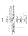
- Fig. 2 is an illustrative view of a voice packet loss concealment method according to the first embodiment of the present invention.
- the packet segment (segment) 1 shown in Fig. 2 is a head segment where a voice packet is received first, while the segment 9 is a segment where a voice packet is received last, assuming that the voice packet in the segment 5 among the segments 1 to 9 is lost.
- the segments 1 to 4 indicate segments before the segment 5 where each voice packet is received normally, while the segments 6 to 9 indicate segments after the segment 5 where each voice packet is also received normally. Voice packets received in the segments 6 to 9 are accumulated in the receive-packet buffer 34.
- the estimation of the pitch fluctuation characteristics and the power fluctuation characteristics using a signal for two packets in the receiving terminal 30 means using two post-loss packets and two pre-loss packets.
- the pitch fluctuation characteristics and the power fluctuation characteristics are estimated using PCM signals, respectively, for 2N samples after the lost segment and 2N samples before the lost segment.
- the number of packets is not restricted to two, allowing the use of a desired number of packets.
- the signal length required for estimation by the receiving terminal 30 is at least a length capable of extracting the pitch cycle. To reproduce the pitch cycle of a human voice, in the case of PCM at 8kHz sampling rate, 20 to 140 samples are needed.
- the voice packet loss concealment device 1 uses voice packets before and after a voice packet lost segment to estimate the pitch cycle fluctuation and the power fluctuation of the lost segment, which allows a more accurate estimation in comparison with a device that estimates a lost voice packet using only a pre-loss voice packet.
- the voice packet loss concealment device 1 is provided with a receive buffer capable of constantly retaining latest two previous and next frames (2N samples) of data among received data, and an output buffer.
- Fig. 3 is a principle block diagram of the present invention.
- the voice packet loss concealment device 1 shown in Fig. 3 comprises a packet loss determining section (detecting section) 33b, a voice characteristics estimating section (estimating section) 39, a pitch signal generating section 33e, a power fluctuation adding section (lost packet generating section) 33f, an output packet switching section 33g, and an output-packet buffer 33h. It is noted that the receive-packet buffer 34 is the same as mentioned above.
- the packet loss determining section 33b which detects the loss of a voice packet and outputs information relating to a lost segment, operates as a detecting section.
- the packet loss determining section 33b detects a lost segment based on the packet number (consecutively assigned packet sequence number) contained in a voice packet.
- the packet loss determining section 33b outputs whether or not there is any voice packet loss as a packet loss determination result, for example, by monitoring packet numbers of voice packets accumulated in the receive-packet buffer 34.
- the output packet switching section 33g outputs selectively a loss concealment packet outputted from the power fluctuation adding section 33f or a received voice packet based on a determination signal outputted from the packet loss determining section 33b, indicating whether or not there is any voice packet loss.
- the output-packet buffer 33h accumulates voice packets for at least 2N (N represents a natural number) samples before a lost segment, which is required for voice processing, among the voice packets accumulated in the receive-packet buffer 34.
- These voice packets for 2N samples include PCM data for two segments, i. e., 2N sets of PCM data sampled from two consecutive voice data before the lost segment. Therefore, the receiving terminal 30 constantly retains latest two previous and next frames (2N samples) of data.
- the voice characteristics estimating section 39 estimates the voice characteristics of a voice packet lost segment (lost voice packet) using a pre-loss voice packet received before the lost segment and a post-loss voice packet received after the lost segment.
- the voice characteristics estimating section 39 uses a lost segment that is detected by the packet loss determining section 33b as the lost segment.
- the voice characteristics estimating section 39 can also use a lost segment that has already been incorporated independently or preliminarily.
- the voice characteristics estimating section 39 comprises a pitch fluctuation estimating section (pitch fluctuation characteristics estimating section) 33d and a power fluctuation estimating section (power fluctuation characteristics estimating section) 33c.
- the pitch fluctuation estimating section 33d estimates the pitch fluctuation characteristics of a lost segment based on a post-loss voice packet received after the lost segment among the voice packets accumulated in the receive-packet buffer 34 and a pre-loss voice packet received before the lost segment among 2N sets of voice packets accumulated in the output-packet buffer 33h.
- the pitch fluctuation estimating section 33d will hereinafter be described in detail with reference to Fig. 7.
- the power fluctuation estimating section 33c estimates the power fluctuation characteristics of the lost segment based on the post-loss voice packet and the pre-loss voice packet.
- the power fluctuation estimating section 33c will hereinafter be described in detail with reference to Fig. 6.
- the voice characteristics estimating section 39 has a function of estimating the pitch fluctuation characteristics and the power fluctuation characteristics of the lost segment as the voice characteristics, using the pitch fluctuation characteristics of the post-loss voice packet, the power fluctuation characteristics of the pre-loss voice packet, the pitch fluctuation characteristics of the pre-loss voice packet, and the power fluctuation characteristics of the post-loss voice packet.
- the pitch fluctuation estimating section 33d, the power fluctuation estimating section 33c, and the pitch signal generating section 33e all use voice packets that have arrived at the receive-packet buffer 34, which is provided to absorb transmission delay fluctuation. Therefore, it is possible to compensate for the voice quality without a new design or a design change.
- the receiving terminal 30 of the VoIP communication system 100 is provided with the receive-packet buffer 34 to absorb packet transmission delay fluctuation, and a required number of voice packets for compensation of transmission delay fluctuation are accumulated sequentially into the receive-packet buffer 34. That is, post-loss voice packets have already been accumulated in the receive-packet buffer 34 at the time the concealment processing for a lost packet is performed.
- the voice characteristics estimating section 39 estimates the voice characteristics using a post-loss voice packet accumulated in the receive-packet buffer 34 and a pre-loss voice packet accumulated in the output-packet buffer 33h.
- the pitch signal generating section 33e generates a pitch signal having the pitch fluctuation characteristics estimated by the pitch fluctuation estimating section 33d.
- the pitch signal generating section 33e segments (extracts) a pitch signal, which is contained in the post-loss voice packet accumulated in the receive-packet buffer 34 or the pre-loss voice packet accumulated in the output-packet buffer 33h, in accordance with a pitch fluctuation estimated value estimated by the pitch fluctuation estimating section 33d.
- the pitch signal generating section 33e obtains the pitch signal using the post-loss voice packet accumulated in the receive-packet buffer 34 and the pre-loss voice packet accumulated in the output-packet buffer 33h. Further, the pitch signal generating section 33e can generate a concealment signal (element contained in the loss concealment packet) having a smooth pitch fluctuation characteristic. The concrete method for this will hereinafter be described.
- the power fluctuation adding section 33f which outputs the pitch signal generated by the pitch signal generating section 33e, with the power fluctuation characteristics estimated by the power fluctuation estimating section 33c being added thereto, as a loss concealment packet, operates as a lost packet generating section.
- the power fluctuation adding section 33f outputs the concealment signal from the pitch signal generating section 33e, inserting it into the loss concealment packet.
- the output packet switching section 33g outputs selectively the loss concealment packet outputted from the power fluctuation adding section 33f or a received normal voice packet from the receive-packet buffer 34 based on the determination signal outputted from the packet loss determining section 33b.
- the conventional method uses only the information contained in preceding received voice packets to avoid an increase in transmission delay.
- the voice packet loss concealment method of the present invention provides the receive-packet buffer 34 to absorb transmission delay fluctuation in the receiving terminal 30. Since the receiving terminal 30 originally accepts delay for compensating for transmission fluctuation in the receive-packet buffer 34, the voice packet loss concealment device 1 can utilize voice packets in the receive-packet buffer 34 effectively whereby no other delay or increase in the amount of delay occurs in the voice packet loss concealment device 1.
- Fig. 4 is an illustrative flow chart of the voice packet loss concealment method according to the first embodiment of the present invention.
- step A1 voice packets that arrive at the receiving terminal 30 at an irregular interval are inputted to the receive-packet buffer 34 to be accumulated as preprocessed voice packets.
- the receive-packet buffer 34 accumulates the arriving voice packets sequentially, and then outputs the accumulated voice packets in the accumulated order to the output packet switching section 33g at a regular interval that is synchronized with the reproduction interval of the voice reproducing device 32a (refer to Fig. 1).
- the output-packet buffer 33h accumulates sequentially the voice packets outputted from the output packet switching section 33g. When the accumulated number of voice packets has reached the buffer size, the output-packet buffer 33h discards the oldest voice packet to accumulate the latest output voice packet.
- step A2 the packet loss determining section 33b detects whether or not there is any voice packet loss (refer to Formula (F6) to be described hereinafter) by checking the packet number (sequence number) of a voice packet to be output next, which is accumulated in the receive-packet buffer 34, and then outputs a voice packet loss determination result to the output packet switching section 33g.
- Formula (F6) to be described hereinafter
- the packet loss determining section 33b when detecting a voice packet loss, the packet loss determining section 33b inputs a voice packet before the lost voice packet (i.e., pre-loss voice packet) accumulated in the output-packet buffer 33h and a voice packet after the lost voice packet accumulated in the receive-packet buffer 34 to the power fluctuation estimating section 33c, the pitch fluctuation estimating section 33d, and the pitch signal generating section 33e.
- a voice packet before the lost voice packet i.e., pre-loss voice packet
- the packet loss determining section 33b inputs a voice packet before the lost voice packet (i.e., pre-loss voice packet) accumulated in the output-packet buffer 33h and a voice packet after the lost voice packet accumulated in the receive-packet buffer 34 to the power fluctuation estimating section 33c, the pitch fluctuation estimating section 33d, and the pitch signal generating section 33e.
- step A3 the power fluctuation estimating section 33c estimates the power fluctuation characteristics of the lost voice packet segment using the voice packets for two packets (2N samples) before and after the loss, and then outputs a power fluctuation estimated value to the power fluctuation adding section 33f.
- step A4 the pitch fluctuation estimating section 33d estimates the pitch fluctuation characteristics of the lost voice packet segment using pre-loss and post-loss voice packets, and then outputs a pitch fluctuation estimated value to the pitch signal generating section 33e.
- step A5 the pitch signal generating section 33e generates a pitch signal having the estimated pitch fluctuation characteristics using the pitch fluctuation estimated value estimated by the pitch fluctuation estimating section 33d and the pre-loss voice packets accumulated in the output-packet buffer 33h. It is noted that the generated pitch signal is inputted to the power fluctuation adding section 33f.
- step A6 the power fluctuation adding section 33f adds the power fluctuation estimated value estimated by the power fluctuation estimating section 33c to the pitch signal from the pitch signal generating section 33e, and then outputs the added pitch signal to the output packet switching section 33g as a loss concealment packet (loss concealment packet).
- the output packet switching section 33g outputs one of two types of voice packets by switching selectively to the voice reproducing device 32a (refer to Fig. 1) depending on the voice packet loss determination result from the packet loss determining section 33b. That is, when the voice packet loss determination result indicates "voice packet lost", the output packet switching section 33g outputs the loss concealment packet from the power fluctuation adding section 33f, otherwise outputs a normal voice packet outputted from the receive-packet buffer 34 at a regular interval.
- the output-packet buffer 33h is arranged in such a manner as to store sequentially voice packets outputted from the output packet switching section 33g, and then input the stored voice packets as pre-loss voice packets to each of the power fluctuation estimating section 33c, the pitch fluctuation estimating section 33d, and the pitch signal generating section 33e as shown in Fig. 3.
- the voice packet loss concealment device 1 utilizes accumulated voice packets that have arrived at the receive-packet buffer 34, which is provided to absorb voice packet transmission delay fluctuation.
- the voice packet loss concealment device 1 also allows a more accurate estimation in comparison with the prior art that estimates a lost voice packet using only a pre-loss voice packet, in that two voice packets (2N samples) before and after a voice packet lost segment are used to estimate the pitch fluctuation and the power fluctuation of the lost segment.
- the voice packet loss concealment method of the present invention is employed in the receiving terminal 30 that receives voice packets containing voice data, and further the receiving terminal 30 is used in the VoIP communication system 100 in which voice data is packetized and transmitted.
- the packet loss determining section 33b of the receiving terminal 30 detects the loss of a voice packet (refer to I shown in Fig. 2) and outputs a detection signal containing information relating to the lost segment 5.
- the voice characteristics estimating section 39 of the receiving terminal 30 estimates the voice characteristics of the lost segment using the voice packets received, respectively, in the segments 3 and 4 before the detected lost segment 5, and estimates the voice characteristics of the lost segment using the voice packets received, respectively, in the segments 6 and 7 after the lost segment 5. In these estimations, the voice characteristics estimating section 39 estimates the pitch fluctuation characteristics and the power fluctuation characteristics of the lost segment 5 using the voice packets received, respectively, in the segments 3, 4, 6 and 7 before and after the lost segment 5 among voice packets accumulated in the receive-packet buffer 34, which is provided to absorb transmission delay fluctuation in a transmission channel (refer to II shown in Fig. 2).
- the power fluctuation adding section (lost packet generating section) 33f of the receiving terminal 30 generates a loss concealment voice packet for the lost segment based on the estimated voice characteristics (pitch fluctuation characteristics and power fluctuation characteristics) (refer to III shown in Fig. 2).
- the pitch fluctuation and the power fluctuation of the lost voice packet are estimated using the normal voice packets 1 to 4 before voice packet loss and the normal voice packets 6 to 9 after voice packet loss accumulated in the receive-packet buffer 34.
- the non-packetization unit 33 (shown in Fig. 1) generates a loss concealment packet for the voice packet lost segment based on the estimated physical characteristics.
- the loss concealment packet is generated by adding the pitch fluctuation characteristics and the power fluctuation characteristics.
- the generated loss concealment packet is also inserted into the segment of the lost voice packet 5 (refer to IV shown in Fig. 2).
- the post-loss voice packet can be read out and utilized.
- Fig. 5 is a block diagram of the voice packet loss concealment device 1 according to the first embodiment of the present invention.
- the voice packet loss concealment device 1 shown in Fig. 5 is provided in the receiving terminal 30 of the VoIP communication system 100, in which voice packets obtained by packetizing voice data for each N-sample (N represents a natural number) are transmitted via the asynchronous transmission channel (IP network) 101.
- IP network asynchronous transmission channel
- a voice packet IPK (n) that has arrived at the receiving terminal 30 is accumulated into the receive-packet buffer 34.
- "n" represents the packet number (sequence number) of the voice packet.
- the voice packet IPK (n) has a header section (voice packet header section) containing information required for transmission (not shown in the figure), the header section will not be taken into consideration to facilitate the following description. Therefore, the following description will be given on the assumption that one voice packet IPK (n) consists only of N samples of voice data as indicated by Formula (F1).
- IPK ( n ) ⁇ pk ( n ,0), pk ( n ,1),..., pk ( n, N - 1) ⁇
- voice packets inputted to the receive-packet buffer 34 include transmission delay fluctuation in the asynchronous transmission channel 101 and arrive at an irregular interval.
- the voice packets are stored sequentially into the receive-packet buffer 34 as indicated by Formula (F2).
- RBUF indicates the receive-packet buffer 34.
- "nrpk” represents the number of voice packets stored in the receive-packet buffer 34, the value of which can be each value from 0 to the buffer size RBUFSIZE of the receive-packet buffer 34.
- the buffer size RBUFSIZE which can be set to a desired value, is set appropriately in accordance with the fluctuation state in the asynchronous transmission channel 101.
- the oldest voice packet RBUF (0) in terms of time is to be outputted to the output packet switching section 33g as PK (m) and updates the receive-packet buffer 34 for each output, as indicated by Formula (F3).
- PK m
- F3 Formula (F3).
- "m” represents a natural number. where the output time interval of voice packets is a regular interval that is synchronized with reproduction processing.
- the receive-packet buffer 34 sets a variable "revbuf” to 2N samples of voice data (PCM data) accumulated therein, as indicated by Formula (F4), and then outputs them to the power fluctuation estimating section 33c and the pitch fluctuation estimating section 33d.
- "rbuf” is element data of voice packets stored in RBUF, which can be represented by Formula (F5).
- RBUF ( m ) ⁇ rbuf ( m ,0), rbuf ( m ,1),..., rbuf ( m, N - 1) ⁇
- the receive-packet buffer 34 outputs the sequence number "seq" of a preceding (to be outputted next) voice packet RBUF (0) in terms of time among voice packets stored in RBUF to the packet loss determining section 33b.
- the output-packet buffer 33h updates voice packets stored therein as indicated by Formula (F7), and then stores sequentially voice packets OPK outputted from the output packet switching section 33g.
- OBUF in OBUF are constantly stored latest two voice packets in terms of time among the output voice packets.
- the output-packet buffer 33h stores voice data (PCM data) for 2N samples into “outbuf” as indicated by Formula (F8), and outputs them to the power fluctuation estimating section 33c, the pitch fluctuation estimating section 33d, and the pitch signal generating section 33e.
- "obuf" is element data of voice packets stored in OBUF, which can be represented by Formula (F9).
- OBUF ( m ) ⁇ obuf ( m ,0), obuf ( m ,1),..., obuf ( m, N - 1) ⁇
- Fig. 6 is a block diagram of the power fluctuation estimating section 33c according to the first embodiment of the present invention.
- the power fluctuation estimating section 33c shown in Fig. 6 comprises a power calculating part (signal power calculating part) 35a and a power fluctuation calculating part (power fluctuation characteristics calculating part) 35b.
- the numerals 34 and 33h indicate the same as mentioned above.
- the power calculating part 35a calculates a first signal power (variable "pow (0)") using the post-loss voice packet accumulated in the receive-packet buffer 34, and calculates a second signal power (variable "pow (1)") using the pre-loss voice packet accumulated in the output-packet buffer 33h. Also, the power fluctuation calculating part 35b calculates the power fluctuation characteristics of the lost segment based on the first signal power and the second signal power calculated by the power calculating part 35a.
- the power calculating part 35a calculates the pre-loss signal power "pow (0)” and the post-loss signal power “pow (1)” using, respectively, “revbuf” inputted from the receive-packet buffer 34 and “outbuf” inputted from the output-packet buffer 33h as indicated by Formula (F10), and outputs the calculated values to the power fluctuation calculating part 35b.
- "i" represents an integer of 0 or more, while “ ⁇ ” a sum. That is, “pow (0)” indicates a sum of “outbuf (i) 2 " from N to 2N-1, while “pow (1)” indicates a sum of "revbuf (i) 2 " from 0 to N-1.
- the power fluctuation calculating part 35b calculates the power fluctuation characteristics of the lost segment based on "pow (0) " and "pow (1) " calculated by the power calculating part 35a. To be concrete, the power fluctuation calculating part 35b calculates the power fluctuation characteristics "rpow” of the lost voice packet segment using "pow (0)" and “pow (1)” as indicated by Formula (F11), and outputs the calculated value to the power fluctuation adding section 33f.
- rpow pow(1) / pow(0)
- the power fluctuation estimating section 33c can also use the pre-loss voice packet accumulated in the output-packet buffer 33h to obtain the power fluctuation characteristics. This allows a more natural voice to be obtained.
- Fig. 7 is a block diagram of the pitch fluctuation estimating section 33d according to the first embodiment of the present invention.
- the pitch fluctuation estimating section 33d shown in Fig. 7 comprises a pitch searching part 36a and a pitch fluctuation calculating part (pitch fluctuation characteristics calculating part) 36b. It is noted that the numerals 34 and 33h indicate the same as mentioned above.
- the pitch searching part 36a shown in Fig. 7 searches a first pitch cycle "lag (0)" using the post-loss voice packet accumulated in the receive-packet buffer 34, and searches a second pitch cycle "lag (1)” using the pre-loss voice packet accumulated in the output-packet buffer 33h.
- the pitch searching part 36a searches "k (kmax0 and kmax1)" that maximize, respectively, R0 (k) and R1 (k) shown in Formula (F12), and outputs "kmax0" and "kmax1” searched to the pitch fluctuation calculating part 36b, respectively, as pitch cycles "lag (0)" and "lag (1)".
- the range to be searched for "k" (LAGMIN to LAGMAX) can be set desirably, e.g., between 20 and 120 samples.
- ⁇ indicates a sum from 0 to N-1.
- the pitch fluctuation calculating part 36b calculates the pitch cycle "lag (0)" using a signal for two packets (2N samples) before the lost segment, while the pitch cycle "lag (1) " using a signal for two packets (2N samples) after the lost segment.
- the pitch fluctuation calculating part 36b calculates the pitch fluctuation characteristics "dlag” using inputted "lag (0)" and "lag (1)", as indicated by Formula (F13), and outputs a pitch fluctuation estimated value to the pitch signal generating section 33e.
- ILAG ⁇ ⁇ is an interpolation function, with which the pitch fluctuation characteristics "dlag” for each sample from the pre-loss pitch cycle "lag (0)" to the post-loss pitch cycle "lag (1)” is to be outputted.
- the pitch fluctuation calculating part 36b can also use a desired interpolation function, e.g., linear function or quadratic function.
- N represents the number of samples in a frame.
- the pitch fluctuation estimating section 33d can also use the pre-loss voice packet accumulated in the output-packet buffer 33h to obtain the pitch fluctuation characteristics.
- the pitch signal generating section 33e generates a pitch signal "pitsig” having the pitch fluctuation characteristics "dlag".
- the pitch signal generating section 33e generates a pitch signal using a portion of "pitsig (1) (1 > 0)" that has already been generated, while in the case “dlag” is not an integer, generates a preceding pitch signal that corresponds to the non-integral pitch cycle by means of, for example, an interpolation from surrounding samples.
- the power fluctuation adding section 33f adds the power fluctuation characteristics "rpow” to the pitch signal "pitsig” using Formula (F16) and calculates a loss concealment signal "cpk". where "/N" indicates a division by N.
- the power fluctuation adding section 33f outputs a loss concealment packet CPK having "cpk” as an element to the output packet switching section 33g.
- CPK ( m ) ⁇ cpk (0), cpk (1),..., cpk ( N - 1) ⁇
- the output packet switching section 33g switches the output voice packet OPK in accordance with the voice packet loss determination result "eflag" as indicated by Formula (F18).
- the output packet switching section 33g outputs a loss concealment packet when a voice packet loss is detected, otherwise outputs a normal voice packet outputted from the receive-packet buffer 34.
- the receiving terminal 30 of the present invention has been adapted to comprise the receive-packet buffer 34 for accumulating voice packets; the packet loss determining section 33b for detecting the loss of a packet using the voice packets accumulated in the receive-packet buffer 34; the output-packet buffer 33h for accumulating preceding output voice packets; the pitch fluctuation estimating section 33d for estimating the pitch fluctuation characteristics of the lost voice packet based on post-loss voice packets received after the lost segment among the voice packets accumulated in the receive-packet buffer 34 and pre-loss voice packets for 2N samples received before the lost segment among the voice packets accumulated in the output-packet buffer 33h; the power fluctuation estimating section 33c for estimating the power fluctuation characteristics of the lost voice packet based on the post-loss voice packets and the pre-loss voice packets; the pitch signal generating section 33e for generating a pitch signal having the pitch fluctuation characteristics estimated by the power fluctuation estimating sections 33c; the power fluctuation
- the pitch cycle and the power fluctuation of a lost segment are estimated using voice packets before and after the voice packet lost segment. Therefore, it is possible to make a more accurate estimation in comparison with the prior art that estimates using only a pre-loss voice packet.
- the receive-packet buffer 34 is essentially provided to absorb voice packet transmission delay fluctuation, whereby the delay for compensating for fluctuation in the receive-packet buffer 34 is originally accepted. Therefore, no other increase in the amount of delay due to the voice packet loss concealment method of the present invention occurs.
- a loss concealment packet having a smooth pitch fluctuation characteristic and a smooth power fluctuation characteristic to a post-loss normal voice packet, which allows abnormal noise due to pitch cycle mismatch and feeling of mute due to signal power attenuation to be suppressed, and subjective deterioration of both naturalness and continuity due to voice packet loss to be further improved in comparison with the prior art.
- Fig. 8 is a block diagram of a voice packet loss concealment device according to a second embodiment of the present invention.
- a pitch signal generating section 33e of the voice packet loss concealment device 1b shown in Fig. 8 is adapted to output a pitch signal by multiplying a predetermined weighting coefficient to each of the pre-loss and post-loss power fluctuation characteristics, and adding the weighted pre-loss and post-loss power fluctuation characteristics to each other.
- the pitch signal generating section 33e generates a pitch signal "pitsig0" corresponding to the pitch fluctuation characteristics "dlag" based on a pre-loss voice signal "outbuf”, as indicated by Formula (F19A).
- the pitch signal generating section 33e generates a pitch signal by adding a pre-loss voice packet with a first weighting coefficient being multiplied thereto and a post-loss voice packet with a second weighting coefficient being multiplied thereto. That is, the pitch signal generating section 33e outputs a composite pitch signal obtained by adding: a first pitch signal obtained using the pre-loss voice packet, with the first weighting coefficient due to the power fluctuation characteristics estimated by the power fluctuation estimating section 33c being multiplied thereto; and a second pitch signal obtained using the post-loss voice packet, with the second weighting coefficient due to the power fluctuation characteristics estimated by the power fluctuation estimating section 33c being multiplied thereto, as the pitch signal.
- the pitch signal generating section 33e generates a pitch signal "pitsig1" corresponding to the pitch fluctuation characteristics "dlag” based on a post-loss voice signal "revbuf”, as indicated by Formula (F19B).
- the pitch signal generating section 33e generates a pitch signal using a portion of "pitsig (1) (1 ⁇ N)" that has already been generated, while in the case “dlag” is not an integer, generates a following pitch signal that corresponds to the non-integral pitch cycle by means of, for example, an interpolation from surrounding samples.
- the pitch signal generating section 33e sets "w" to 0.5 or more to increase and add the weight of a loss concealment signal that is generated based on the post-loss signal.
- the composite pitch signal is obtained by switching various weighting coefficients, resulting in voice quality improvement. Moreover, an appropriate pitch signal that takes voice data into consideration can be obtained, generating a natural voice that fluctuates smoothly. Also, the composite pitch signal is obtained by switching various weighting coefficients, resulting in further voice quality improvement.
- the pitch signal generating section 33e is arranged to generate the pitch signal by applying a weighting addition to each of the pitch fluctuation characteristics and the power fluctuation characteristics of the post-loss voice packet in the case the lost segment corresponds to the first transition segment from one including no voice to another including the rise of the voice.
- the second embodiment it is possible to generate a signal more approximate to the original signal than a loss concealment signal generated from a pre-loss signal as in the first embodiment, which allows deterioration of naturalness and continuity in voice segments to be further suppressed.
- the pitch signal generating section 33e can improve the voice quality in the rise part by setting the weighting coefficient "w" to 0.5 or more in, for example, the case of a "rpow” higher than a threshold value RP_TH (i.e., a drastic power increase), while setting "w" to 0.0 in the case of one lower than the threshold value.
- RP_TH i.e., a drastic power increase
- Fig. 9 is a block diagram of a voice packet loss concealment device according to a third embodiment of the present invention.
- the voice packet loss concealment device 1c shown in Fig. 9 has a monitor function for monitoring the number of voice packets accumulated in a receive-packet buffer 34, and a function for changing the operation pattern (operation mode) of a pitch fluctuation estimating section 33d, a power fluctuation estimating section 33c, and a pitch signal generating section 33e in accordance with the number of voice packets acquired by the monitor function.
- Functions other than above are the same as that of the voice packet loss concealment device 1b of the second embodiment.
- elements shown in Fig. 9 having the same numerals as above are the same as mentioned above. Descriptions about the same elements as in the second embodiment will hereinafter be omitted to describe the operation of different elements.
- An accumulated packet number monitoring section 33i shown in Fig. 9 outputs a selection signal that indicates one of either pre-loss voice packet or post-loss voice packet based on the number of voice packets accumulated in the receive-packet buffer 34.
- the accumulated packet number monitoring section 33i is provided with the number of voice packets "nrpk" stored in the receive-packet buffer 34, and outputs a flag "rflag” to each of the pitch fluctuation estimating section 33d, the power fluctuation estimating section 33c, and the pitch signal generating section 33e in accordance with "nrpk", as indicated by Formula (F22).
- the pitch fluctuation estimating section 33d calculates only a pitch cycle "lag (1)" of the post-loss segment in a pitch searching part 36a (refer to Fig. 7) by means of the same method as the first embodiment. Then, the pitch fluctuation calculating part 36b calculates the pitch fluctuation characteristics "dlag” using Formula (F23), and outputs a calculated value to the pitch signal generating section 33e.
- old_lag lag(l)
- OILAG ⁇ ⁇ indicates an extrapolation function, wherein the pitch fluctuation calculating part 36b changes the pitch cycle from "old_lag” in the pre-loss segment to "lag (1)” to extrapolate and output the pitch fluctuation characteristics "dlag" for each sample after the change of pitch cycle (lost segment). It is possible to use a desired extrapolation function, e.g., linear function or quadratic function.
- the accumulated packet number monitoring section 33i inputs the flag "rflag", which indicates a process pattern according to the number of voice packets accumulated in the receive-packet buffer 34, to each of the pitch fluctuation estimating section 33d, the power fluctuation estimating section 33c, and the pitch signal generating section 33e. That is, the accumulated packet number monitoring section 33i can control the pitch fluctuation estimating section 33d, the power fluctuation estimating section 33c, and the pitch signal generating section 33e respectively according to the number of voice packets.
- the power fluctuation estimating section 33c calculates only a power "pow (1)" of the post-loss segment in a power calculating part 35a (refer to Fig. 6) by means of the same method as the first embodiment. Then, the power fluctuation estimating section 33c calculates the power fluctuation characteristics "rpow” using Formula (F25).
- rpow pow(l) / old_pow where "old_pow” represents a preceding calculated "pow (1)" (immediately before), which is updated using Formula (F26) after every calculation of Formula (F25).
- old_pow pow(l)
- the pitch signal generating section 33e generates a pitch signal "pitsig" having the pitch fluctuation characteristics "dlag" by means of the same method as the first embodiment, as indicated by Formula (F27). That is, the pre-loss signal is only be used.
- the pitch fluctuation estimating section 33d the power fluctuation estimating section 33c, and the pitch signal generating section 33e all perform the same processing as that in the second embodiment.
- the pitch signal generating section 33e attenuates the loss concealment signal gradually to minimize auditory deterioration.
- FIG. 10(a) to 10(c) For pitch fluctuation, while Figs. 11(a) to 11(c) for power fluctuation.
- both Figs. 10(a) and 11(a) show original voice waveforms.
- Both Figs. 10(b) and 11(b) show processed waveforms according to the publicly known document 1 (G.711 Appendix I), while both Figs. 10(c) and 11(c) show processed waveforms obtained by using the present voice packet loss concealment method.
- G.711 Appendix I the publicly known document 1
- Figs. 10(c) and 11(c) show processed waveforms obtained by using the present voice packet loss concealment method.
- a packet loss concealed segment is indicated in each waveform.
- the waveform shown in Fig. 10(a) is an original voice waveform without voice packet loss.
- the waveform shown in Fig. 10(a) appears a characteristic shape repeatedly.
- the time interval between "peaks" or “troughs" of the repeating waveform unit corresponds to a pitch cycle (pitch cycle 1, pitch cycle 2).
- the pitch cycle includes fluctuation and thereby changes slightly from pitch cycle 1 to pitch cycle 2 as shown in Fig. 10(a) .
- the voice packet loss concealment device 1 (1a to 1c) inserts the same partial waveform P1 repeatedly based on prediction.
- the waveform shown in Fig. 10(c) is for the case where the post-loss pitch cycle (pitch cycle 2) is shorter than the pre-loss pitch cycle (pitch cycle 1), being adapted in such a manner that the pitch cycle in the lost segment gets close to that of the post-loss signal.
- the gradual pitch cycle reduction suppresses pitch cycle shift to improve the mismatch at the connection. In addition, this allows abnormal noise to be eliminated also subjectively.
- the pitch fluctuation calculating part 36b generates a concealment signal in such a manner as to change from the pre-loss pitch cycle to the post-loss pitch cycle, whereby the pitch cycle of the loss concealed segment changes for each pitch (to be more accurate, for each sample).
- the pitch fluctuation calculating part 36b generates a signal corresponding to this pitch fluctuation and calculates a pitch lag value for each sample as indicated by Formula (F13).
- the prior art uses an identical pitch cycle constantly, and therefore the pitch peak of the waveform shown in Fig. 10(b) shifts rightward in comparison with the original voice waveform.
- the waveform shown in Fig. 11(a) is an original voice waveform without voice packet loss.
- the vertical axis indicates the voice amplitude.
- the waveform shown in Fig. 11(b) shows an amplitude fluctuation wherein the amplitude attenuates gradually to fade out.
- the voice packet loss concealment devices 1, 1a to 1c can generate a concealment signal having a smooth pitch fluctuation characteristic and a smooth power fluctuation characteristic from a pre-loss normal voice packet to a post-loss normal voice packet. This allows abnormal noise due to pitch cycle mismatch and feeling of mute due to signal power attenuation to be suppressed, and subjective deterioration of both naturalness and continuity due to voice packet loss to be further improved in comparison with the prior art.
- Communication systems or networks to which the present invention is applied are not restricted to VoIP communication system, but may encompass, for example, VoATM in an ATM (Asynchronous Transfer Mode) network and VoFR that utilizes a high-speed digital line via an FR (Frame Relay) exchange.
- VoATM in an ATM (Asynchronous Transfer Mode) network
- VoFR that utilizes a high-speed digital line via an FR (Frame Relay) exchange.
- VoATM and VoFR transmit packets via a gateway for packetizing telephone voice, etc., allowing a real-time voice communication .
- VoATM improves voice quality, and allows transmission delay, transmission delay fluctuation, or voice packet loss to be improved considerably. Further, using VoFR can obtain relatively high-level voice quality with a low cost.
- the waveforms of a loss concealment packet and a voice packet received normally after a packet loss are connected smoothly, which allows both abnormal noise due to pitch cycle mismatch and feeling of mute due to signal power attenuation to be suppressed, and subjective deterioration of auditory naturalness and continuity caused by voice packet loss to be improved.
Abstract
Description


Claims (19)
- A voice packet loss concealment device comprising:an estimating section for estimating the voice characteristics of a voice packet lost segment using at least one of either a pre-loss voice packet received before said lost segment or a post-loss voice packet received after said lost segment;a pitch signal generating section for generating a pitch signal having the voice characteristics estimated by said estimating section; anda lost packet generating section for outputting said pitch signal generated by said pitch signal generating section, with the voice characteristics estimated by said estimating section being added thereto, as a loss concealment packet.
- The voice packet loss concealment device according to claim 1, wherein said estimating section estimates a third pitch fluctuation characteristic of said lost segment and a third power fluctuation characteristic of said lost segment as the voice characteristics, using a first pitch fluctuation characteristic of said post-loss voice packet and a first power fluctuation characteristic of said post-loss voice packet, and a second pitch fluctuation characteristic of said pre-loss voice packet and a second power fluctuation characteristic of said pre-loss voice packet.
- The voice packet loss concealment device according to claim 1 or 2, comprising a receive buffer for accumulating received voice packets, wherein said receive buffer is used as an absorption buffer for absorbing packet transmission delay fluctuation.
- The voice packet loss concealment device according to any one of claims 1 to 3, further comprising an output buffer for accumulating one or more voice packets required for voice processing among the voice packets accumulated in said receive buffer, wherein said estimating section estimates the voice characteristics using said post-loss voice packet accumulated in said receive buffer and said pre-loss voice packet accumulated in said output buffer.
- The voice packet loss concealment device according to claim 3, comprising an accumulated packet number monitoring section for outputting a selection signal that indicates one of either pre-loss voice packet or post-loss voice packet based on the number of voice packets accumulated in said receive buffer.
- A voice packet loss concealment device comprising:a receive buffer for accumulating voice packets;a detecting section for detecting the loss of a voice packet and outputting information relating to a lost segment;an output buffer for accumulating one or more voice packets required for voice processing among the voice packets accumulated in said receive buffer;a pitch fluctuation characteristics estimating section for estimating the pitch fluctuation characteristics of said lost segment based on a post-loss voice packet received after said lost segment among the voice packets accumulated in said receive buffer and a pre-loss voice packet received before said lost segment among one or more voice packets accumulated in said output buffer;a power fluctuation characteristics estimating section for estimating the power fluctuation characteristics of said lost segment based on said post-loss voice packet and said pre-loss voice packet;a pitch signal generating section for generating a pitch signal having the voice characteristics estimated by said estimating section; anda lost packet generating section for outputting said pitch signal generated by said pitch signal generating section, with the power fluctuation characteristics estimated by said power fluctuation characteristics estimating section being added thereto, as a loss concealment packet.
- The voice packet loss concealment device according to claim 6, wherein said pitch fluctuation characteristics estimating section comprises:a pitch searching part for searching a first pitch cycle using said post-loss voice packet accumulated in said receive buffer and a second pitch cycle using said pre-loss voice packet accumulated in said output buffer; anda pitch fluctuation characteristics calculating part for calculating the pitch fluctuation characteristics of said lost segment based on said first pitch cycle and said second pitch cycle searched by said pitch searching part, and outputting a pitch fluctuation estimated value.
- The voice packet loss concealment device according to claim 6, wherein said power fluctuation characteristics estimating section comprises:a signal power calculating part for calculating a first signal power using said post-loss voice packet accumulated in said receive buffer and a second signal power using said pre-loss voice packet accumulated in said output buffer; anda power fluctuation characteristics calculating part for calculating the power fluctuation characteristics of said lost segment based on said first signal power and said second signal power calculated by said signal power calculating part.
- The voice packet loss concealment device according to claim 6, comprising:a pitch signal generating section for generating a pitch signal having the pitch fluctuation characteristics estimated by said pitch fluctuation characteristics estimating section;a lost packet generating section for outputting said pitch signal generated by said pitch signal generating section, with the power fluctuation characteristics estimated by said power fluctuation characteristics estimating section being added thereto, as said loss concealment packet; andan output packet switching section for selectively outputting said loss concealment packet outputted from said lost packet generating section or a received normal voice packet from said receive buffer based on a determination signal outputted from said detecting section, indicating whether or not there is any voice packet loss.
- The voice packet loss concealment device according to claim 9, wherein said pitch signal generating section extracts a pitch signal, which is contained in said post-loss voice packet accumulated in said receive buffer or said pre-loss voice packet accumulated in said output buffer, in accordance with a pitch fluctuation estimated value estimated by said pitch fluctuation characteristics estimating section.
- The voice packet loss concealment device according to claim9, wherein said pitch signal generating section outputs a composite pitch signal obtained by adding:a first pitch signal obtained using said post-loss voice packet, with a first weighting coefficient due to the power fluctuation characteristics estimated by said power fluctuation characteristics estimating section being multiplied thereto; anda second pitch signal obtained using said pre-loss voice packet, with a second weighting coefficient due to the power fluctuation characteristics estimated by said power fluctuation characteristics estimating section being multiplied thereto, as said pitch signal.
- The voice packet loss concealment device according to claim 9, wherein said pitch fluctuation characteristics estimating section obtains the pitch fluctuation characteristics using said pre-loss voice packet accumulated in said output buffer in the case there is accumulated no post-loss voice packet in said receive buffer.
- The voice packet loss concealment device according to claim 9, wherein said power fluctuation characteristics estimating section obtains the power fluctuation characteristics using said pre-loss voice packet accumulated in said output buffer in the case there is accumulated no post-loss voice packet in said receive buffer.
- A voice packet loss concealment device comprising:a receive buffer for accumulating voice packets;a packet loss determining section for detecting the loss of a packet using the voice packets accumulated in said receive buffer;an output buffer for accumulating one or more voice packets required for voice processing among the voice packets accumulated in said receive buffer;a pitch fluctuation characteristics estimating section for estimating the pitch fluctuation characteristics of said lost voice packet based on a post-loss voice packet received after said lost segment among the voice packets accumulated in said receive buffer and a pre-loss voice packet received before said lost segment among one or more voice packets accumulated in said output buffer;a power fluctuation characteristics estimating section for estimating the power fluctuation characteristics of said lost voice packet based on said post-loss voice packet and said pre-loss voice packet;a pitch signal generating section for generating a pitch signal having the pitch fluctuation characteristics estimated by said pitch fluctuation characteristics estimating section;a lost packet generating section for outputting said pitch signal generated by said pitch signal generating section, with the power fluctuation characteristics estimated by said power fluctuation characteristics estimating section being added thereto, as said loss concealment packet; andan output packet switching section for selectively outputting said loss concealment packet outputted from said lost packet generating section or a received normal voice packet from said receive buffer based on a detection signal.
- The voice packet loss concealment device according to any one of claims 9 to 14, wherein said pitch signal generating section generates said pitch signal by applying a weighting addition to each of the pitch fluctuation characteristics and the power fluctuation characteristics of said post-loss voice packet in the case said lost segment corresponds to the first transition segment from one including no voice to another including the rise of said voice.
- A receiving terminal in a voice communication system in which voice data is packetized and transmitted, comprising:a receive buffer for accumulating received voice packets;a detecting section for detecting the loss of a voice packet using the voice packets accumulated in said receive buffer and outputting information relating to a lost segment;an estimating section for estimating the voice characteristics of said lost segment using at least one of either a pre-loss voice packet received before said lost segment that is detected by said detecting section or a post-loss voice packet received after said lost segment;a pitch signal generating section for generating a pitch signal having the voice characteristics estimated by said estimating section; anda lost packet generating section for outputting said pitch signal generated by said pitch signal generating section, with the voice characteristics estimated by said estimating section being added thereto, as a loss concealment packet.
- A voice packet loss concealment method in a receiving terminal provided in a voice communication system in which voice data is packetized and transmitted, wherein:a detecting section of said receiving terminal detects the loss of said voice packet and outputs a detection signal containing information relating to at least a lost segment;an estimating section of said receiving terminal estimates the voice characteristics of said lost segment using voice packets received before and after said detected lost segment;a pitch signal generating section of said receiving terminal generates a pitch signal having the estimated voice characteristics; anda lost packet generating section of said receiving terminal outputs said generated pitch signal, with the estimated voice characteristics being added thereto, as a loss concealment packet.
- The voice packet loss concealment method according to claim 17, wherein:said estimating section of said receiving terminal estimates the pitch fluctuation characteristics and the power fluctuation characteristics of said lost segment using voice packets before and after said lost segment among the voice packets accumulated in a receive buffer that is provided to absorb transmission delay fluctuation in a transmission channel;said pitch signal generating section of said receiving terminal generates a pitch signal having the estimated voice characteristics; andsaid lost packet generating section of said receiving terminal outputs said generated pitch signal, with the estimated voice characteristics being added thereto, as a loss concealment packet.
- A voice communication system in which voice data is packetized and transmitted, wherein a receiving terminal for receiving voice packets containing said voice data comprises:a detecting section for detecting the loss of a voice packet and outputting information relating to a lost segment;an estimating section for estimating the voice characteristics of said lost segment using at least one of either a pre-loss voice packet received before said lost segment that is detected by said detecting section or a post-loss voice packet received after said lost segment;a pitch signal generating section for generating a pitch signal having the voice characteristics estimated by said estimating section; anda lost packet generating section for outputting said pitch signal generated by said pitch signal generating section, with the voice characteristics estimated by said estimating section being added thereto, as a loss concealment packet.
Applications Claiming Priority (1)
| Application Number | Priority Date | Filing Date | Title |
|---|---|---|---|
| PCT/JP2003/000894 WO2004068098A1 (en) | 2003-01-30 | 2003-01-30 | Audio packet vanishment concealing device, audio packet vanishment concealing method, reception terminal, and audio communication system |
Publications (3)
| Publication Number | Publication Date |
|---|---|
| EP1589330A1 true EP1589330A1 (en) | 2005-10-26 |
| EP1589330A4 EP1589330A4 (en) | 2007-07-11 |
| EP1589330B1 EP1589330B1 (en) | 2009-04-22 |
Family
ID=32800815
Family Applications (1)
| Application Number | Title | Priority Date | Filing Date |
|---|---|---|---|
| EP03815584A Expired - Fee Related EP1589330B1 (en) | 2003-01-30 | 2003-01-30 | Audio packet vanishment concealing device, audio packet vanishment concealing method, reception terminal, and audio communication system |
Country Status (5)
| Country | Link |
|---|---|
| US (1) | US7650280B2 (en) |
| EP (1) | EP1589330B1 (en) |
| JP (1) | JP4303687B2 (en) |
| DE (1) | DE60327371D1 (en) |
| WO (1) | WO2004068098A1 (en) |
Cited By (3)
| Publication number | Priority date | Publication date | Assignee | Title |
|---|---|---|---|---|
| DE102007018484A1 (en) * | 2007-03-20 | 2008-09-25 | Fraunhofer-Gesellschaft zur Förderung der angewandten Forschung e.V. | Apparatus and method for transmitting a sequence of data packets and decoder and apparatus for decoding a sequence of data packets |
| GB2508811A (en) * | 2012-10-31 | 2014-06-18 | Csr Technology Inc | Packet loss concealment in decoded signals |
| EP4099323A3 (en) * | 2021-09-13 | 2023-05-31 | Apollo Intelligent Connectivity (Beijing) Technology Co., Ltd. | Packet loss recovery method for audio data packet, electronic device and storage medium |
Families Citing this family (26)
| Publication number | Priority date | Publication date | Assignee | Title |
|---|---|---|---|---|
| US7590047B2 (en) * | 2005-02-14 | 2009-09-15 | Texas Instruments Incorporated | Memory optimization packet loss concealment in a voice over packet network |
| US7433358B1 (en) * | 2005-07-08 | 2008-10-07 | Cisco Technology, Inc. | Characterization of impaired intervals in a voice over packet session using audio frame loss concealment |
| US8018917B2 (en) * | 2005-11-21 | 2011-09-13 | Cisco Technology, Inc. | System and method for facilitating network performance analysis |
| FR2899993A1 (en) * | 2006-04-18 | 2007-10-19 | France Telecom | METHOD FOR NOTIFYING A TRANSMISSION DEFECT OF AN AUDIO SIGNAL |
| WO2008007698A1 (en) * | 2006-07-12 | 2008-01-17 | Panasonic Corporation | Lost frame compensating method, audio encoding apparatus and audio decoding apparatus |
| US8015000B2 (en) * | 2006-08-03 | 2011-09-06 | Broadcom Corporation | Classification-based frame loss concealment for audio signals |
| US8346546B2 (en) * | 2006-08-15 | 2013-01-01 | Broadcom Corporation | Packet loss concealment based on forced waveform alignment after packet loss |
| JP4504389B2 (en) * | 2007-02-22 | 2010-07-14 | 富士通株式会社 | Concealment signal generation apparatus, concealment signal generation method, and concealment signal generation program |
| JP5233986B2 (en) * | 2007-03-12 | 2013-07-10 | 富士通株式会社 | Speech waveform interpolation apparatus and method |
| US7710973B2 (en) * | 2007-07-19 | 2010-05-04 | Sofaer Capital, Inc. | Error masking for data transmission using received data |
| JP2009063928A (en) * | 2007-09-07 | 2009-03-26 | Fujitsu Ltd | Interpolation method and information processing apparatus |
| CN101207665B (en) * | 2007-11-05 | 2010-12-08 | 华为技术有限公司 | Method for obtaining attenuation factor |
| CN101437009B (en) * | 2007-11-15 | 2011-02-02 | 华为技术有限公司 | Method for hiding loss package and system thereof |
| US20090180531A1 (en) * | 2008-01-07 | 2009-07-16 | Radlive Ltd. | codec with plc capabilities |
| WO2009116972A1 (en) * | 2008-03-20 | 2009-09-24 | Thomson Licensing | System and method for processing priority transport stream data in real time in a multi-channel broadcast multimedia system |
| EP2289065B1 (en) * | 2008-06-10 | 2011-12-07 | Dolby Laboratories Licensing Corporation | Concealing audio artifacts |
| WO2009150290A1 (en) * | 2008-06-13 | 2009-12-17 | Nokia Corporation | Method and apparatus for error concealment of encoded audio data |
| JP5694745B2 (en) * | 2010-11-26 | 2015-04-01 | 株式会社Nttドコモ | Concealment signal generation apparatus, concealment signal generation method, and concealment signal generation program |
| EP3855430B1 (en) * | 2013-02-05 | 2023-10-18 | Telefonaktiebolaget LM Ericsson (publ) | Method and appartus for controlling audio frame loss concealment |
| US9706317B2 (en) * | 2014-10-24 | 2017-07-11 | Starkey Laboratories, Inc. | Packet loss concealment techniques for phone-to-hearing-aid streaming |
| CN105741843B (en) * | 2014-12-10 | 2019-09-20 | 辰芯科技有限公司 | A kind of lost packet compensation method and system based on delay jitter |
| JP6387308B2 (en) * | 2015-02-02 | 2018-09-05 | 日本電信電話株式会社 | Voice quality estimation apparatus, method and program |
| US9712930B2 (en) * | 2015-09-15 | 2017-07-18 | Starkey Laboratories, Inc. | Packet loss concealment for bidirectional ear-to-ear streaming |
| JP6586044B2 (en) * | 2016-05-13 | 2019-10-02 | 日本電信電話株式会社 | Speech quality estimation apparatus, speech quality estimation method and program |
| JP7331588B2 (en) * | 2019-09-26 | 2023-08-23 | ヤマハ株式会社 | Information processing method, estimation model construction method, information processing device, estimation model construction device, and program |
| CN112669858A (en) | 2019-10-14 | 2021-04-16 | 上海华为技术有限公司 | Data processing method and related device |
Citations (3)
| Publication number | Priority date | Publication date | Assignee | Title |
|---|---|---|---|---|
| WO1999066494A1 (en) * | 1998-06-19 | 1999-12-23 | Comsat Corporation | Improved lost frame recovery techniques for parametric, lpc-based speech coding systems |
| JP2001228896A (en) * | 2000-02-14 | 2001-08-24 | Iwatsu Electric Co Ltd | Substitution exchange method of lacking speech packet |
| WO2002007061A2 (en) * | 2000-07-14 | 2002-01-24 | Conexant Systems, Inc. | A speech communication system and method for handling lost frames |
Family Cites Families (12)
| Publication number | Priority date | Publication date | Assignee | Title |
|---|---|---|---|---|
| JPH05268685A (en) * | 1992-03-17 | 1993-10-15 | Matsushita Electric Ind Co Ltd | Private automatic branch exchange |
| JP3286110B2 (en) * | 1995-03-16 | 2002-05-27 | 松下電器産業株式会社 | Voice packet interpolation device |
| US5929921A (en) | 1995-03-16 | 1999-07-27 | Matsushita Electric Industrial Co., Ltd. | Video and audio signal multiplex sending apparatus, receiving apparatus and transmitting apparatus |
| US5907822A (en) * | 1997-04-04 | 1999-05-25 | Lincom Corporation | Loss tolerant speech decoder for telecommunications |
| JP2000059391A (en) | 1998-08-11 | 2000-02-25 | Hitachi Commun Syst Inc | Audio packet transmitting/receiving method, audio packet transmission terminal and audio packet reception terminal |
| EP1088303B1 (en) * | 1999-04-19 | 2006-08-02 | AT & T Corp. | Method and apparatus for performing frame erasure concealment |
| US6584438B1 (en) * | 2000-04-24 | 2003-06-24 | Qualcomm Incorporated | Frame erasure compensation method in a variable rate speech coder |
| FR2813722B1 (en) | 2000-09-05 | 2003-01-24 | France Telecom | METHOD AND DEVICE FOR CONCEALING ERRORS AND TRANSMISSION SYSTEM COMPRISING SUCH A DEVICE |
| JP2002162998A (en) * | 2000-11-28 | 2002-06-07 | Fujitsu Ltd | Voice encoding method accompanied by packet repair processing |
| DE60233283D1 (en) * | 2001-02-27 | 2009-09-24 | Texas Instruments Inc | Obfuscation method in case of loss of speech frames and decoder dafer |
| JP3628268B2 (en) * | 2001-03-13 | 2005-03-09 | 日本電信電話株式会社 | Acoustic signal encoding method, decoding method and apparatus, program, and recording medium |
| US20030220787A1 (en) * | 2002-04-19 | 2003-11-27 | Henrik Svensson | Method of and apparatus for pitch period estimation |
-
2003
- 2003-01-30 DE DE60327371T patent/DE60327371D1/en not_active Expired - Lifetime
- 2003-01-30 JP JP2004567529A patent/JP4303687B2/en not_active Expired - Fee Related
- 2003-01-30 EP EP03815584A patent/EP1589330B1/en not_active Expired - Fee Related
- 2003-01-30 WO PCT/JP2003/000894 patent/WO2004068098A1/en active Application Filing
-
2005
- 2005-02-24 US US11/065,416 patent/US7650280B2/en not_active Expired - Fee Related
Patent Citations (3)
| Publication number | Priority date | Publication date | Assignee | Title |
|---|---|---|---|---|
| WO1999066494A1 (en) * | 1998-06-19 | 1999-12-23 | Comsat Corporation | Improved lost frame recovery techniques for parametric, lpc-based speech coding systems |
| JP2001228896A (en) * | 2000-02-14 | 2001-08-24 | Iwatsu Electric Co Ltd | Substitution exchange method of lacking speech packet |
| WO2002007061A2 (en) * | 2000-07-14 | 2002-01-24 | Conexant Systems, Inc. | A speech communication system and method for handling lost frames |
Non-Patent Citations (2)
| Title |
|---|
| "Pulse code modulation (PCM) of voice frequencies" ITU-T STANDARD IN FORCE (I), INTERNATIONAL TELECOMMUNICATION UNION, GENEVA,, CH, no. G711 Appendix I 9, 1 September 1999 (1999-09-01), XP017400851 * |
| See also references of WO2004068098A1 * |
Cited By (8)
| Publication number | Priority date | Publication date | Assignee | Title |
|---|---|---|---|---|
| DE102007018484A1 (en) * | 2007-03-20 | 2008-09-25 | Fraunhofer-Gesellschaft zur Förderung der angewandten Forschung e.V. | Apparatus and method for transmitting a sequence of data packets and decoder and apparatus for decoding a sequence of data packets |
| WO2008113455A1 (en) * | 2007-03-20 | 2008-09-25 | Fraunhofer-Gesellschaft zur Förderung der angewandten Forschung e.V. | Device and method for sending a sequence of data packets and decoder and device for decoding a sequence of data packets |
| DE102007018484B4 (en) * | 2007-03-20 | 2009-06-25 | Fraunhofer-Gesellschaft zur Förderung der angewandten Forschung e.V. | Apparatus and method for transmitting a sequence of data packets and decoder and apparatus for decoding a sequence of data packets |
| US8385366B2 (en) | 2007-03-20 | 2013-02-26 | Fraunhofer-Gesellschaft Zur Foerderung Der Angewandten Forschung E.V. | Apparatus and method for transmitting a sequence of data packets and decoder and apparatus for decoding a sequence of data packets |
| EP3217583A1 (en) | 2007-03-20 | 2017-09-13 | Fraunhofer-Gesellschaft zur Förderung der angewandten Forschung e.V. | Decoder and method for decoding a sequence of packets |
| GB2508811A (en) * | 2012-10-31 | 2014-06-18 | Csr Technology Inc | Packet loss concealment in decoded signals |
| US9325544B2 (en) | 2012-10-31 | 2016-04-26 | Csr Technology Inc. | Packet-loss concealment for a degraded frame using replacement data from a non-degraded frame |
| EP4099323A3 (en) * | 2021-09-13 | 2023-05-31 | Apollo Intelligent Connectivity (Beijing) Technology Co., Ltd. | Packet loss recovery method for audio data packet, electronic device and storage medium |
Also Published As
| Publication number | Publication date |
|---|---|
| US7650280B2 (en) | 2010-01-19 |
| JP4303687B2 (en) | 2009-07-29 |
| US20050166124A1 (en) | 2005-07-28 |
| DE60327371D1 (en) | 2009-06-04 |
| EP1589330A4 (en) | 2007-07-11 |
| WO2004068098A1 (en) | 2004-08-12 |
| JPWO2004068098A1 (en) | 2006-05-18 |
| EP1589330B1 (en) | 2009-04-22 |
Similar Documents
| Publication | Publication Date | Title |
|---|---|---|
| US7650280B2 (en) | Voice packet loss concealment device, voice packet loss concealment method, receiving terminal, and voice communication system | |
| EP1746580B1 (en) | Acoustic signal packet communication method, transmission method, reception method, and device and program thereof | |
| EP1746581B1 (en) | Sound packet transmitting method, sound packet transmitting apparatus, sound packet transmitting program, and recording medium in which that program has been recorded | |
| EP1458145A1 (en) | Error concealment apparatus and method | |
| EP1202251A2 (en) | Transcoder for prevention of tandem coding of speech | |
| TWI420513B (en) | Audio packet loss concealment by transform interpolation | |
| US20020097807A1 (en) | Wideband signal transmission system | |
| JP4485690B2 (en) | Transmission system for transmitting multimedia signals | |
| US6871175B2 (en) | Voice encoding apparatus and method therefor | |
| JPH01155400A (en) | Voice encoding system | |
| Sanneck | Concealment of lost speech packets using adaptive packetization | |
| JP3566931B2 (en) | Method and apparatus for assembling packet of audio signal code string and packet disassembly method and apparatus, program for executing these methods, and recording medium for recording program | |
| US20080294428A1 (en) | Packet loss concealment | |
| KR100594599B1 (en) | Apparatus and method for restoring packet loss based on receiving part | |
| KR100911771B1 (en) | A apparatus of packet loss concealment with realtime voice communication on internet and method thereof | |
| Bakri et al. | An improved packet loss concealment technique for speech transmission in VOIP | |
| US20100185441A1 (en) | Error Concealment | |
| KR100542435B1 (en) | Method and apparatus for frame loss concealment for packet network | |
| KR100591544B1 (en) | METHOD AND APPARATUS FOR FRAME LOSS CONCEALMENT FOR VoIP SYSTEMS | |
| US7586937B2 (en) | Receiving device and method | |
| Issing et al. | Adaptive playout for VoIP based on the enhanced low delay AAC audio codec | |
| US20030055515A1 (en) | Header for signal file temporal synchronization | |
| JP2000059391A (en) | Audio packet transmitting/receiving method, audio packet transmission terminal and audio packet reception terminal | |
| Nam et al. | Adaptive playout algorithm using packet expansion for the VoIP | |
| Liu | Time scale modification of digital audio signals and its applications |
Legal Events
| Date | Code | Title | Description |
|---|---|---|---|
| PUAI | Public reference made under article 153(3) epc to a published international application that has entered the european phase |
Free format text: ORIGINAL CODE: 0009012 |
|
| 17P | Request for examination filed |
Effective date: 20050301 |
|
| AK | Designated contracting states |
Kind code of ref document: A1 Designated state(s): AT BE BG CH CY CZ DE DK EE ES FI FR GB GR IE IT LI LU MC NL PT SE SK TR |
|
| RIN1 | Information on inventor provided before grant (corrected) |
Inventor name: TSUCHINAGA, Y., FUJITSU NETWORK TECH. LTD. Inventor name: SAWA, MIYUKI, C/O FUJITSU KYUSHU DIGITAL TECH LTD. Inventor name: TANAKA, MASAKIYO, C/O FUJITSU LIMITED Inventor name: SUZUKI, MASANAO, C/O FUJITSU LIMITED Inventor name: OTA, YASUJI, C/O FUJITSU LIMITED |
|
| RBV | Designated contracting states (corrected) |
Designated state(s): DE FR GB |
|
| RIN1 | Information on inventor provided before grant (corrected) |
Inventor name: TANAKA, MASAKIYO,C/O FUJITSU LIMITED Inventor name: SUZUKI, MASANAO,C/O FUJITSU LIMITED Inventor name: TSUCHINAGA, YOSHITERU,FUJITSU NETWORK TECH. LTD. Inventor name: OTA, YASUJI,C/O FUJITSU LIMITED Inventor name: SAWA, MIYUKI,C/O FUJITSU NETWORK TECH. LTD. |
|
| A4 | Supplementary search report drawn up and despatched |
Effective date: 20070611 |
|
| RIN1 | Information on inventor provided before grant (corrected) |
Inventor name: SUZUKI, MASANAO,C/O FUJITSU LIMITED Inventor name: TANAKA, MASAKIYO,C/O FUJITSU LIMITED Inventor name: SHIRAKAWA,MIYUKIC/O FUJITSU NETWORK TECH. LTD. Inventor name: TSUCHINAGA, YOSHITERU,FUJITSU NETWORK TECH. LTD. Inventor name: OTA, YASUJI,C/O FUJITSU LIMITED |
|
| 17Q | First examination report despatched |
Effective date: 20070927 |
|
| GRAP | Despatch of communication of intention to grant a patent |
Free format text: ORIGINAL CODE: EPIDOSNIGR1 |
|
| RIC1 | Information provided on ipc code assigned before grant |
Ipc: G10L 19/00 20060101AFI20080626BHEP |
|
| RIN1 | Information on inventor provided before grant (corrected) |
Inventor name: SHIRAKAWA,MIYUKIC/O FUJITSU NETWORK TECH. LTD. Inventor name: OTA, YASUJI,C/O FUJITSU LIMITED Inventor name: TANAKA, MASAKIYO,C/O FUJITSU LIMITED Inventor name: SUZUKI, MASANAO,C/O FUJITSU LIMITED Inventor name: TSUCHINAGA, YOSHITERU,FUJITSU NETWORK TECH. LTD. |
|
| GRAS | Grant fee paid |
Free format text: ORIGINAL CODE: EPIDOSNIGR3 |
|
| GRAA | (expected) grant |
Free format text: ORIGINAL CODE: 0009210 |
|
| AK | Designated contracting states |
Kind code of ref document: B1 Designated state(s): DE FR GB |
|
| REG | Reference to a national code |
Ref country code: GB Ref legal event code: FG4D |
|
| REF | Corresponds to: |
Ref document number: 60327371 Country of ref document: DE Date of ref document: 20090604 Kind code of ref document: P |
|
| PLBE | No opposition filed within time limit |
Free format text: ORIGINAL CODE: 0009261 |
|
| STAA | Information on the status of an ep patent application or granted ep patent |
Free format text: STATUS: NO OPPOSITION FILED WITHIN TIME LIMIT |
|
| 26N | No opposition filed |
Effective date: 20100125 |
|
| PGFP | Annual fee paid to national office [announced via postgrant information from national office to epo] |
Ref country code: DE Payment date: 20110126 Year of fee payment: 9 Ref country code: FR Payment date: 20110128 Year of fee payment: 9 |
|
| PGFP | Annual fee paid to national office [announced via postgrant information from national office to epo] |
Ref country code: GB Payment date: 20110126 Year of fee payment: 9 |
|
| GBPC | Gb: european patent ceased through non-payment of renewal fee |
Effective date: 20120130 |
|
| REG | Reference to a national code |
Ref country code: FR Ref legal event code: ST Effective date: 20120928 |
|
| PG25 | Lapsed in a contracting state [announced via postgrant information from national office to epo] |
Ref country code: DE Free format text: LAPSE BECAUSE OF NON-PAYMENT OF DUE FEES Effective date: 20120801 Ref country code: GB Free format text: LAPSE BECAUSE OF NON-PAYMENT OF DUE FEES Effective date: 20120130 |
|
| REG | Reference to a national code |
Ref country code: DE Ref legal event code: R119 Ref document number: 60327371 Country of ref document: DE Effective date: 20120801 |
|
| PG25 | Lapsed in a contracting state [announced via postgrant information from national office to epo] |
Ref country code: FR Free format text: LAPSE BECAUSE OF NON-PAYMENT OF DUE FEES Effective date: 20120131 |