EP1589300A1 - Connector of a tubular element, in particular the connector of a condenser-integrated dryer tank of a refrigerating system - Google Patents
Connector of a tubular element, in particular the connector of a condenser-integrated dryer tank of a refrigerating system Download PDFInfo
- Publication number
- EP1589300A1 EP1589300A1 EP04460011A EP04460011A EP1589300A1 EP 1589300 A1 EP1589300 A1 EP 1589300A1 EP 04460011 A EP04460011 A EP 04460011A EP 04460011 A EP04460011 A EP 04460011A EP 1589300 A1 EP1589300 A1 EP 1589300A1
- Authority
- EP
- European Patent Office
- Prior art keywords
- connector
- tubular element
- header
- condenser
- dryer tank
- Prior art date
- Legal status (The legal status is an assumption and is not a legal conclusion. Google has not performed a legal analysis and makes no representation as to the accuracy of the status listed.)
- Withdrawn
Links
Images


Classifications
-
- F—MECHANICAL ENGINEERING; LIGHTING; HEATING; WEAPONS; BLASTING
- F28—HEAT EXCHANGE IN GENERAL
- F28F—DETAILS OF HEAT-EXCHANGE AND HEAT-TRANSFER APPARATUS, OF GENERAL APPLICATION
- F28F9/00—Casings; Header boxes; Auxiliary supports for elements; Auxiliary members within casings
- F28F9/02—Header boxes; End plates
- F28F9/0246—Arrangements for connecting header boxes with flow lines
-
- F—MECHANICAL ENGINEERING; LIGHTING; HEATING; WEAPONS; BLASTING
- F25—REFRIGERATION OR COOLING; COMBINED HEATING AND REFRIGERATION SYSTEMS; HEAT PUMP SYSTEMS; MANUFACTURE OR STORAGE OF ICE; LIQUEFACTION SOLIDIFICATION OF GASES
- F25B—REFRIGERATION MACHINES, PLANTS OR SYSTEMS; COMBINED HEATING AND REFRIGERATION SYSTEMS; HEAT PUMP SYSTEMS
- F25B39/00—Evaporators; Condensers
- F25B39/04—Condensers
-
- F—MECHANICAL ENGINEERING; LIGHTING; HEATING; WEAPONS; BLASTING
- F25—REFRIGERATION OR COOLING; COMBINED HEATING AND REFRIGERATION SYSTEMS; HEAT PUMP SYSTEMS; MANUFACTURE OR STORAGE OF ICE; LIQUEFACTION SOLIDIFICATION OF GASES
- F25B—REFRIGERATION MACHINES, PLANTS OR SYSTEMS; COMBINED HEATING AND REFRIGERATION SYSTEMS; HEAT PUMP SYSTEMS
- F25B43/00—Arrangements for separating or purifying gases or liquids; Arrangements for vaporising the residuum of liquid refrigerant, e.g. by heat
- F25B43/006—Accumulators
-
- F—MECHANICAL ENGINEERING; LIGHTING; HEATING; WEAPONS; BLASTING
- F28—HEAT EXCHANGE IN GENERAL
- F28F—DETAILS OF HEAT-EXCHANGE AND HEAT-TRANSFER APPARATUS, OF GENERAL APPLICATION
- F28F9/00—Casings; Header boxes; Auxiliary supports for elements; Auxiliary members within casings
- F28F9/001—Casings in the form of plate-like arrangements; Frames enclosing a heat exchange core
- F28F9/002—Casings in the form of plate-like arrangements; Frames enclosing a heat exchange core with fastening means for other structures
-
- F—MECHANICAL ENGINEERING; LIGHTING; HEATING; WEAPONS; BLASTING
- F25—REFRIGERATION OR COOLING; COMBINED HEATING AND REFRIGERATION SYSTEMS; HEAT PUMP SYSTEMS; MANUFACTURE OR STORAGE OF ICE; LIQUEFACTION SOLIDIFICATION OF GASES
- F25B—REFRIGERATION MACHINES, PLANTS OR SYSTEMS; COMBINED HEATING AND REFRIGERATION SYSTEMS; HEAT PUMP SYSTEMS
- F25B2339/00—Details of evaporators; Details of condensers
- F25B2339/04—Details of condensers
- F25B2339/044—Condensers with an integrated receiver
- F25B2339/0441—Condensers with an integrated receiver containing a drier or a filter
-
- F—MECHANICAL ENGINEERING; LIGHTING; HEATING; WEAPONS; BLASTING
- F25—REFRIGERATION OR COOLING; COMBINED HEATING AND REFRIGERATION SYSTEMS; HEAT PUMP SYSTEMS; MANUFACTURE OR STORAGE OF ICE; LIQUEFACTION SOLIDIFICATION OF GASES
- F25B—REFRIGERATION MACHINES, PLANTS OR SYSTEMS; COMBINED HEATING AND REFRIGERATION SYSTEMS; HEAT PUMP SYSTEMS
- F25B2339/00—Details of evaporators; Details of condensers
- F25B2339/04—Details of condensers
- F25B2339/044—Condensers with an integrated receiver
- F25B2339/0446—Condensers with an integrated receiver characterised by the refrigerant tubes connecting the header of the condenser to the receiver; Inlet or outlet connections to receiver
Definitions
- the invention relates to a connector of a tubular element, in particular a connector of a dryer tank integrated with the header of a refrigerating system condenser, such as vehicle air conditioning system.
- the condenser and dryer tank commonly form two separate units, connected to each other by means of appropriate pipes, however in order to minimize the installation space there have been proposed constructions of a dryer integrated condensers.
- U.S. Pat. No 5,546,761 discloses a condenser fluidly connected to a cylindrical liquid tank by means of at least two coupling brackets, being secured to an outer cylindrical surface of the header and an outer cylindrical surface of the liquid tank by means of brazing. Brackets comprise an additional passageway pipe inserted fixedly into the bracket, enabling the flow of a coolant between the header and the liquid tank. It has been also proposed to bond the condenser header and the dryer together by brazing.
- the aim of the present invention is to provide a connector of a tubular element, having a simple, economical construction, which allows the brazing of this element to another longitudinal element with no need to modify the second element, and which ensures a precise, rigid connection of these elements, as well as durability for mechanical vibrations, and, where necessary, enables a high pressure, leakproof flow communication between these elements.
- the aim of the present invention is to provide a connector of a dryer tank that will be able to be integrated with the typical header of condenser of a refrigerating system.
- a connector of a tubular element which has the form of a shape stamped in a side surface of the tubular element, said shape having at least two convex arms at each side of the tubular element longitudinal axis and a butting face defined by the arms, wherein the shape of the butting face corresponds to the side surface of the longitudinal element, bonded to the tubular element by brazing.
- longitudinal element as used herein, is to be understood as an element having a substantially constant cross-section, which length is greater than its diameter.
- the connectors are stamped in the tubular element side surface during its manufacture from a metal sheet, which is subsequently bent cylindrically and closed e.g. by an overlap, the tubular element is already accommodated to be bonded to the longitudinal element with no need to perform additional assembling operations or to provide additional connectors or other connecting means.
- the connector construction ensures a controlled zone of brazing. Brazing takes place only on the butting face of the connector, which is large enough to provide a good durability of the connection.
- tubular element and/or the longitudinal element side surface is/are covered by a clad layer, which greatly facilitates the brazing operation.
- the braze does not flow along the tubular and/or longitudinal element surface but due to a capillary brazing effect, is sucked into the gap between the side surface of the longitudinal element and the connector butting face, thus creating a durable connection.
- tubular element is a dryer tank and the longitudinal element is the header of the condenser of a refrigerating system.
- the shape of the connector does not influence the dryer bore or internal passage, which is advantageous in case additional elements, such as a desiccant bag, are going to be placed inside the dryer.
- the butting face of the connector preferably has an orifice corresponding to the appropriate orifice of the longitudinal element.
- orifices allows the flow of coolant between the header and the dryer tank.
- the orifice is preferably made by lancing and has a collar.
- the collar increases the sealability of the connection, and ensures and prevents the braze flowing inside the header.
- the disclosed embodiment concerns connectors of a dryer tank integrated with the header of a vehicle air conditioning system condenser, therefore the tubular element is referred to below as the dryer tank and the longitudinal element as the header.
- the longitudinal element may also have another cross-section other than circular, e.g. elliptical or even square.
- the condenser 1 shown in Fig. 1 is a part of the refrigerating cycle of a vehicle air conditioning system, not shown in detail in the drawings, and is connected between the compressor and the expansion valve in a manner known to a person skilled in the art.
- the condenser is made of aluminium alloy and comprises a cooling core 2 consisting of plural parallel tubes and cooling fins, and two cylindrical headers 3 fluidly connected to the reciprocal ends of each tube.
- the cylindrical dryer 4 is fluidly connected to one header by means of three connectors 5a and 5b, the lower two of which enable flow of the coolant between the condenser header 3 and the dryer tank 4, while the top one serves only as a mounting point.
- Each connector has the form of a shape stamped in the side surface of the dryer tank 4.
- the stamps were made during the manufacture of the dryer tank 4 from an aluminium sheet covered by a clad layer. After stamping the connectors, the sheet, forming the dryer tank 4 was subsequently bent cylindrically and closed by an overlap 41. The completed dryer tank is a non-serviceable part closed by two end caps 42.
- Fig. 2 shows the header 3 and the dryer tank 4 before the brazing operation.
- Each connector 5a and 5b has two convex arms 51 and 52 on each side of the dryer tank. The arms define the butting surface 53 of the connector that corresponds to the shape of the header 3 that will be bonded to the dryer tank.
- connectors 5b comprise orifices 54 for the flow of coolant between the header and the dryer tank.
- Fig. 3A show the connector 5a in an axonometric view and Fig. 4A in horizontal cross-section along the line A-A of Fig. 3a after bonding the dryer tank 4 with the header 3.
- braze 6 is sucked into the gap between the header's side surface and the connector butting face 53, thus creating a durable connection.
- the shape of the connector does not influence the dryer internal passage 43, which is advantageous, since there are no obstacles in placing additional elements, such as a desiccant bag, inside the dryer.
- Fig. 3B and Fig. 4B show the second embodiment of the connector 5b with orifice 54.
- Orifice 54 was made during the stamping of the connector by a lancing technique. Consequently the orifice 54 comprises a shoulder 55 cooperating with an orifice 31 bored in the side surface of the header 3.
- Fig. 5 shows the front view of the connector 5b and Fig. 6 the rear view, i.e. the view from inside the tubular element 3 of the connector 5b.
- the arms 51 and 52 define and delimit the butting face 53, having an area large enough to provide a durable and strong connection.
Landscapes
- Engineering & Computer Science (AREA)
- Physics & Mathematics (AREA)
- Thermal Sciences (AREA)
- Mechanical Engineering (AREA)
- General Engineering & Computer Science (AREA)
- Chemical & Material Sciences (AREA)
- Analytical Chemistry (AREA)
- Power Engineering (AREA)
- Air-Conditioning For Vehicles (AREA)
Abstract
Description
- The invention relates to a connector of a tubular element, in particular a connector of a dryer tank integrated with the header of a refrigerating system condenser, such as vehicle air conditioning system.
- In known vehicle air conditioning systems, the condenser and dryer tank commonly form two separate units, connected to each other by means of appropriate pipes, however in order to minimize the installation space there have been proposed constructions of a dryer integrated condensers.
- An example of such a solution is disclosed in U.S. Pat. No 5,546,761, where a receiver integrated refrigerant condenser, in which the receiver tank is disposed beside the second condenser header, has been presented.
U.S. Pat. No 5,884,503 discloses a condenser fluidly connected to a cylindrical liquid tank by means of at least two coupling brackets, being secured to an outer cylindrical surface of the header and an outer cylindrical surface of the liquid tank by means of brazing. Brackets comprise an additional passageway pipe inserted fixedly into the bracket, enabling the flow of a coolant between the header and the liquid tank.
It has been also proposed to bond the condenser header and the dryer together by brazing. However due to the curvature of these elements, their joint surface of connection does not ensure proper durability, especially during the condenser vibrations caused by vehicle operation. Difficulties arise also due to the required fluid connection between the header and the dryer and consequently due to the necessity of maintaining the high pressure leakproofness of such a connection. - The aim of the present invention is to provide a connector of a tubular element, having a simple, economical construction, which allows the brazing of this element to another longitudinal element with no need to modify the second element, and which ensures a precise, rigid connection of these elements, as well as durability for mechanical vibrations, and, where necessary, enables a high pressure, leakproof flow communication between these elements.
- In particular, the aim of the present invention is to provide a connector of a dryer tank that will be able to be integrated with the typical header of condenser of a refrigerating system.
- In accordance with the present invention there is provided a connector of a tubular element, which has the form of a shape stamped in a side surface of the tubular element, said shape having at least two convex arms at each side of the tubular element longitudinal axis and a butting face defined by the arms, wherein the shape of the butting face corresponds to the side surface of the longitudinal element, bonded to the tubular element by brazing.
- The term "longitudinal element" as used herein, is to be understood as an element having a substantially constant cross-section, which length is greater than its diameter.
- Since the connectors are stamped in the tubular element side surface during its manufacture from a metal sheet, which is subsequently bent cylindrically and closed e.g. by an overlap, the tubular element is already accommodated to be bonded to the longitudinal element with no need to perform additional assembling operations or to provide additional connectors or other connecting means. The connector construction ensures a controlled zone of brazing. Brazing takes place only on the butting face of the connector, which is large enough to provide a good durability of the connection.
- Preferably the tubular element and/or the longitudinal element side surface is/are covered by a clad layer, which greatly facilitates the brazing operation.
- The braze does not flow along the tubular and/or longitudinal element surface but due to a capillary brazing effect, is sucked into the gap between the side surface of the longitudinal element and the connector butting face, thus creating a durable connection.
- It is particularly preferable if the tubular element is a dryer tank and the longitudinal element is the header of the condenser of a refrigerating system.
- It is worth noting that the shape of the connector does not influence the dryer bore or internal passage, which is advantageous in case additional elements, such as a desiccant bag, are going to be placed inside the dryer.
- The butting face of the connector preferably has an orifice corresponding to the appropriate orifice of the longitudinal element.
- If the connector is used to join the dryer tank to the condenser header, orifices allows the flow of coolant between the header and the dryer tank.
- The orifice is preferably made by lancing and has a collar.
- The collar increases the sealability of the connection, and ensures and prevents the braze flowing inside the header.
- The connector, according to the invention, is presented below on the basis of preferred embodiments in connection with the drawings on which:
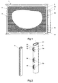
- Fig. 1 is a side view of a condenser-integrated dryer tank with connectors according to the present invention, after bonding condenser elements by brazing;
- Fig. 2 is a top axonometric view of the dryer tank, having three connectors according to the present invention and a condenser header before their preassembling;
- Fig. 3A and Fig. 3B is a top axonometric view of connectors according to the first and the second embodiment of the present invention respectively;
- Fig. 4A and Fig.
4B 3 is a cross-section of connectors according to the first and the second embodiment of the present invention along the line A-A of Fig. 3. - Fig. 5 is a front view of the connector according to the second embodiment of the present invention, and
- Fig. 6 is a rear view of the connector according to the second embodiment of the present invention.
-
- The disclosed embodiment concerns connectors of a dryer tank integrated with the header of a vehicle air conditioning system condenser, therefore the tubular element is referred to below as the dryer tank and the longitudinal element as the header. However it is to be understood, that other applications of connectors according to the present invention, for joining other tubular elements by means of brazing are also possible. The longitudinal element may also have another cross-section other than circular, e.g. elliptical or even square.
- The
condenser 1 shown in Fig. 1 is a part of the refrigerating cycle of a vehicle air conditioning system, not shown in detail in the drawings, and is connected between the compressor and the expansion valve in a manner known to a person skilled in the art. The condenser is made of aluminium alloy and comprises acooling core 2 consisting of plural parallel tubes and cooling fins, and twocylindrical headers 3 fluidly connected to the reciprocal ends of each tube. Thecylindrical dryer 4 is fluidly connected to one header by means of threeconnectors condenser header 3 and thedryer tank 4, while the top one serves only as a mounting point. Each connector has the form of a shape stamped in the side surface of thedryer tank 4. The stamps were made during the manufacture of thedryer tank 4 from an aluminium sheet covered by a clad layer. After stamping the connectors, the sheet, forming thedryer tank 4 was subsequently bent cylindrically and closed by anoverlap 41. The completed dryer tank is a non-serviceable part closed by twoend caps 42. - Fig. 2 shows the
header 3 and thedryer tank 4 before the brazing operation. Eachconnector convex arms butting surface 53 of the connector that corresponds to the shape of theheader 3 that will be bonded to the dryer tank. - Additionally,
connectors 5b compriseorifices 54 for the flow of coolant between the header and the dryer tank. After assembling the condenser, the entire unit is placed in a furnace, where the one-shot brazing process is carried out. - Fig. 3A show the
connector 5a in an axonometric view and Fig. 4A in horizontal cross-section along the line A-A of Fig. 3a after bonding thedryer tank 4 with theheader 3. As shown, during the furnace brazing of these elements, due to a capillary brazing effect, braze 6 is sucked into the gap between the header's side surface and theconnector butting face 53, thus creating a durable connection. - The shape of the connector does not influence the dryer
internal passage 43, which is advantageous, since there are no obstacles in placing additional elements, such as a desiccant bag, inside the dryer. - Fig. 3B and Fig. 4B show the second embodiment of the
connector 5b withorifice 54. Orifice 54 was made during the stamping of the connector by a lancing technique. Consequently theorifice 54 comprises ashoulder 55 cooperating with anorifice 31 bored in the side surface of theheader 3. - Fig. 5 shows the front view of the
connector 5b and Fig. 6 the rear view, i.e. the view from inside thetubular element 3 of theconnector 5b. As shown thearms butting face 53, having an area large enough to provide a durable and strong connection.
Claims (6)
- A connector of a tubular element, characterised in that it has a form of a shape (5a, 5b) stamped in a side surface of the tubular element (4), said shape having at least two convex arms (51, 52) at each side of the tubular element (4) longitudinal axis and an a butting face (53) defined by the arms (51, 52), wherein the shape of the butting face (53) corresponds to the side surface of the longitudinal element (3), bonded to the tubular element (4) by brazing.
- A connector as claimed in claim 1, characterised in that the tubular element (4) and/or the longitudinal element (3) is/are covered by a clad layer.
- A connector as claimed in claim 1 or 2, characterised in that the tubular element is a dryer tank (4) and the longitudinal element is a header (3) of a refrigerating system condenser.
- A connector as claimed in claim 1 or 2, characterised in that the butting face (53) of the connector (5b) has an orifice (54) corresponding to the orifice (31) of the longitudinal element (3).
- A connector as claimed in claim 4, characterised in that the orifice (54) is made by lancing and comprises a collar (55).
- A connector as claimed in claim 1 or 2, characterised in that the tubular element (4) is made of an aluminium alloy.
Priority Applications (1)
| Application Number | Priority Date | Filing Date | Title |
|---|---|---|---|
| EP04460011A EP1589300A1 (en) | 2004-04-21 | 2004-04-21 | Connector of a tubular element, in particular the connector of a condenser-integrated dryer tank of a refrigerating system |
Applications Claiming Priority (1)
| Application Number | Priority Date | Filing Date | Title |
|---|---|---|---|
| EP04460011A EP1589300A1 (en) | 2004-04-21 | 2004-04-21 | Connector of a tubular element, in particular the connector of a condenser-integrated dryer tank of a refrigerating system |
Publications (1)
| Publication Number | Publication Date |
|---|---|
| EP1589300A1 true EP1589300A1 (en) | 2005-10-26 |
Family
ID=34933170
Family Applications (1)
| Application Number | Title | Priority Date | Filing Date |
|---|---|---|---|
| EP04460011A Withdrawn EP1589300A1 (en) | 2004-04-21 | 2004-04-21 | Connector of a tubular element, in particular the connector of a condenser-integrated dryer tank of a refrigerating system |
Country Status (1)
| Country | Link |
|---|---|
| EP (1) | EP1589300A1 (en) |
Cited By (1)
| Publication number | Priority date | Publication date | Assignee | Title |
|---|---|---|---|---|
| US20220235981A1 (en) * | 2019-08-27 | 2022-07-28 | Hanon Systems | Water-cooling type condenser |
Citations (7)
| Publication number | Priority date | Publication date | Assignee | Title |
|---|---|---|---|---|
| JPH02165832A (en) * | 1988-12-15 | 1990-06-26 | Calsonic Corp | Manufacture of tank for heat exchanger |
| US5546761A (en) | 1994-02-16 | 1996-08-20 | Nippondenso Co., Ltd. | Receiver-integrated refrigerant condenser |
| US5628206A (en) * | 1994-04-01 | 1997-05-13 | Nippondenso Co., Ltd. | Refrigerant condenser |
| US5884503A (en) | 1996-10-14 | 1999-03-23 | Calsonic Corporation | Condenser with liquid tank and manufacturing method the same |
| JP2001082836A (en) * | 1999-09-10 | 2001-03-30 | Nippon Light Metal Co Ltd | Liquid receiver |
| FR2815702A1 (en) * | 2000-10-20 | 2002-04-26 | Ebea S A | Method for attaching reservoir to collector tube of heat exchanger comprises mechanical assembly of two components using ribs or crimps on reservoir which fit around tube, followed by welding |
| WO2002081998A1 (en) * | 2001-04-04 | 2002-10-17 | Norsk Hydro Asa | Heat exchanger manifold |
-
2004
- 2004-04-21 EP EP04460011A patent/EP1589300A1/en not_active Withdrawn
Patent Citations (7)
| Publication number | Priority date | Publication date | Assignee | Title |
|---|---|---|---|---|
| JPH02165832A (en) * | 1988-12-15 | 1990-06-26 | Calsonic Corp | Manufacture of tank for heat exchanger |
| US5546761A (en) | 1994-02-16 | 1996-08-20 | Nippondenso Co., Ltd. | Receiver-integrated refrigerant condenser |
| US5628206A (en) * | 1994-04-01 | 1997-05-13 | Nippondenso Co., Ltd. | Refrigerant condenser |
| US5884503A (en) | 1996-10-14 | 1999-03-23 | Calsonic Corporation | Condenser with liquid tank and manufacturing method the same |
| JP2001082836A (en) * | 1999-09-10 | 2001-03-30 | Nippon Light Metal Co Ltd | Liquid receiver |
| FR2815702A1 (en) * | 2000-10-20 | 2002-04-26 | Ebea S A | Method for attaching reservoir to collector tube of heat exchanger comprises mechanical assembly of two components using ribs or crimps on reservoir which fit around tube, followed by welding |
| WO2002081998A1 (en) * | 2001-04-04 | 2002-10-17 | Norsk Hydro Asa | Heat exchanger manifold |
Non-Patent Citations (2)
| Title |
|---|
| PATENT ABSTRACTS OF JAPAN vol. 014, no. 420 (M - 1023) 11 September 1990 (1990-09-11) * |
| PATENT ABSTRACTS OF JAPAN vol. 2000, no. 20 10 July 2001 (2001-07-10) * |
Cited By (1)
| Publication number | Priority date | Publication date | Assignee | Title |
|---|---|---|---|---|
| US20220235981A1 (en) * | 2019-08-27 | 2022-07-28 | Hanon Systems | Water-cooling type condenser |
Similar Documents
| Publication | Publication Date | Title |
|---|---|---|
| JP5351386B2 (en) | Heat exchanger piping connector | |
| US20040089439A1 (en) | Tube-to-tube heat exchanger assembly | |
| US20180259269A1 (en) | Heat exchanger and manufacturing method for the same | |
| CN101011767A (en) | Method of manufacturing heat exchanger and heat exchanger | |
| US7131293B2 (en) | Dryer integrated condenser of a refrigerating system and a method of assembling the same | |
| JP2000346584A (en) | Heat exchanger | |
| JP4167397B2 (en) | Heat exchanger | |
| US20050268645A1 (en) | Condenser for an air conditioning system | |
| US20070181293A1 (en) | Heat exchanger and producing method thereof | |
| JPWO2000033010A1 (en) | heat exchanger | |
| JP2001116489A (en) | Method of forming sacrificial corrosion layer | |
| JP3995527B2 (en) | Heat exchanger with receiver | |
| KR101970966B1 (en) | Pipe connector for heat exchanger | |
| KR20070108078A (en) | How to connect the intermediate assembly and the heat exchanger | |
| JP4707462B2 (en) | Piping connection structure of heat exchanger | |
| JP5802006B2 (en) | Heat exchanger and connection method thereof | |
| US20070204982A1 (en) | Manifolds and manifold connections for heat exchangers | |
| US20070068660A1 (en) | Heat exchanging unit for motor vehicles | |
| JP2004271101A (en) | Heat exchanger with liquid receiver | |
| CN101156042A (en) | Heat exchangers, especially condensers for automobiles | |
| JP2004219027A (en) | Connector mounting structure for capacitors | |
| JPH1183377A (en) | Heat exchanger | |
| JP2936778B2 (en) | Condenser | |
| KR102691884B1 (en) | Heat exchanger | |
| JP2001133191A (en) | Vehicle heat exchanger |
Legal Events
| Date | Code | Title | Description |
|---|---|---|---|
| PUAI | Public reference made under article 153(3) epc to a published international application that has entered the european phase |
Free format text: ORIGINAL CODE: 0009012 |
|
| AK | Designated contracting states |
Kind code of ref document: A1 Designated state(s): AT BE BG CH CY CZ DE DK EE ES FI FR GB GR HU IE IT LI LU MC NL PL PT RO SE SI SK TR |
|
| AX | Request for extension of the european patent |
Extension state: AL HR LT LV MK |
|
| 17P | Request for examination filed |
Effective date: 20060426 |
|
| AKX | Designation fees paid |
Designated state(s): AT BE BG CH CY CZ DE DK EE ES FI FR GB GR HU IE IT LI LU MC NL PL PT RO SE SI SK TR |
|
| RAP1 | Party data changed (applicant data changed or rights of an application transferred) |
Owner name: MAHLE INTERNATIONAL GMBH |
|
| 17Q | First examination report despatched |
Effective date: 20160218 |
|
| GRAP | Despatch of communication of intention to grant a patent |
Free format text: ORIGINAL CODE: EPIDOSNIGR1 |
|
| INTG | Intention to grant announced |
Effective date: 20180718 |
|
| RIC1 | Information provided on ipc code assigned before grant |
Ipc: F28F 9/00 20060101ALI20041018BHEP Ipc: F25B 39/04 20060101AFI20041018BHEP |
|
| STAA | Information on the status of an ep patent application or granted ep patent |
Free format text: STATUS: THE APPLICATION IS DEEMED TO BE WITHDRAWN |
|
| 18D | Application deemed to be withdrawn |
Effective date: 20181129 |