Technical Field
The present invention relates to air conditioners, and
more particularly, to air conditioners capable of enhancing
a user's perception. Preferably, such an air conditioner
includes a display window at one side, so that an image
adapted for the air conditioner or a character image having
a user's high preference is displayed on the display window.
Also, a manipulation operation of the air conditioner is
more convenient through a change of the character image.
Preferably, the air conditioner can suitably display the
character image depending on an operational state, thereby
enhancing a user's perception.
Background Art
An air conditioner that is generally used at home
includes a manipulation part such as a control panel, a
display window on which an operational state of the air
conditioner is displayed, and a driver part having a
plurality of equipments suitable for a characteristic of the
air conditioner. The display window is configured to simply
display the operational state of the air conditioner with
digits, arrows, shades, display of liquid crystal display
(LCD), and so on. Because the display window which allows a
user to observe the operational state of the air conditioner
is constructed too simply, the user cannot observe the
operational state of the air conditioner at a glance. In
other words, the user must look at digits or arrows near the
air conditioner.
Specifically, among home appliances, the air
conditioner is installed in an indoor space or wall of an
office or house so as to heat or cool its interior. The air
conditioner includes a compressor, a condenser, an expansion
value and an evaporator and performs a series of a
refrigeration cycle. Generally, the air conditioner has a
plurality of operational states, such as a dehumidifying
state, a cooling state, and a rapid cooling state. However,
the user must approach the indoor unit of the air
conditioner so as to identify the operational state of the
air conditioner. Even if a display window is installed in an
indoor unit, the user must look at an arrow or appellation
of the operational state near the indoor unit. Also, the
complex operational state of the air conditioner can be
perceived through digits, letters, arrows, symbols, and so
on.
As described above, the conventional air conditioner
has drawbacks in that freshness and animation are lack
because temperature, humidity and operational states are
displayed in a static manner.
Also, an image displayed on the display window is
predefined in a manufacturing step and cannot be changed.
Therefore, the user is liable to be tired of the image and
tends to purchase a new air conditioner, thereby reducing a
use term of the air conditioner.
Meanwhile, a virtual reality using the Internet
connected through networks has been recently in the
spotlight. In such a virtual reality, individuals feel
satisfied on the Internet using their own characters as the
other selves. A variety of contents industries associated
with them are growing. These characters are called "AVATA".
Up to the present, the use of the AVATA is limited to the
virtual space, which is connected through the Internet.
Technical Problem
It would be desirable to provide an air conditioner
having an enhanced user perception, in which a display
window on which a character is displayed is provided at one
side of the air conditioner, thereby improving a user's
preference.
It would also be desirable to provide an air
conditioner having an enhanced user perception, in which a
character image displayed on a display window is changed
depending on an operational state of the air conditioner, so
that a user can perceive the operational state more
conveniently. In order to enhance the user perception much
more, the operational state of the air conditioner can be
presented using a voice or other audible signal.
Also, it would be desirable to provide an air
conditioner, which can enhance a user satisfaction much more
by making a whole set of characters, which are displayed on
a display window, changeable depending on a user's
preference. A use term is also extended.
Further, it would be desirable to provide an air
conditioner, which can enhance a convenience in use of the
air conditioner much more by implementing several kinds of
display arrangement depending on a user's preference.
Further, it would be desirable to provide an air
conditioner having an enhanced user perception, in which a
display window disposed at a front side of the air
conditioner can be stably fixed to increase a readability of
the display window.
Further, it would be desirable to provide an air
conditioner having an enhanced user perception, in which a
display window can be assembled more conveniently and simply
and a manufacturing process can be performed more
conveniently.
Technical Solution
In order to achieve the above objects, there is
provided an air conditioner, or an indoor unit of an air
conditioner, which includes: a frame formed on either side
of the indoor unit of the air conditioner; a base formed on
a rear side of the frame; a heat exchanger disposed at an
inner space between the frame and the base, for performing
heat exchange; an orifice formed at the inner space between
the frame and the base, for guiding airflow; a fan for
generating a forcible blowing; a case disposed at a front
side of the frame; a display driving board disposed on an
inner surface of the case; an image panel controlled by the
display driving board and disposed inside the case; and a
front panel disposed to cover the frame at a position
corresponding to the image panel, and having a transparent
portion.
In another aspect of the present invention, an air
conditioner includes: a front frame and a base forming a
predetermined space therein; a heat exchanger disposed at
the inner space between the frame and the base, for
performing heat exchange, an orifice for guiding airflow,
and fan for generating a forcible blowing; a lower case
formed at a front side of the front frame, and an upper case
coupled with the lower case; an LCD panel driving circuit
board disposed on an inner surface of the lower case; an LCD
panel controlled by a control signal of the LCD panel
driving circuit board; and a front panel disposed to cover
the frame at a position corresponding to the image panel,
and having a transparent portion.
In another aspect of the present invention, an air
conditioner includes: a front panel formed at a front side
of an indoor unit of the air conditioner; a front frame to
which the front panel is fixed; an image display panel
disposed on a portion between the front panel and the front
frame; a board which drives the image display panel and
accommodates at least a storage medium; and a case for
protecting the image display panel and the storage medium.
In another aspect of the present invention, and air
conditioner includes: a front panel formed at a front side
of an indoor unit of the air conditioner; a front frame to
which the front panel is fixed; an image display panel
disposed on a portion between the front panel and the front
frame; a board which drives the image display panel and
accommodates a storage medium storing information related
with a predetermined character at least displayed on the
image display panel; and a case for protecting the image
display panel and the storage medium.
Advantageous Effects
According to the present invention, a user's own
character image can be displayed on an air conditioner, so
that the will to purchase the product and a user's
satisfaction are increased.
Also, a character can be changed depending on a user's
preference, thereby providing more satisfaction to the user.
In addition, since the character can be changed
conveniently, a user's convenience is improved.
Also, an action of a character displayed on an air
conditioner can be visibly changed in various shapes,
depending on characteristics of operational states of the
air conditioner. Therefore, the operational state of the air
conditioner can be easily perceived. Due to a voice output
part, the operational state can be perceived more reliably.
Further, a user can be greatly satisfied by recording his or
her favorite person's voice for the voice output.
Further, in such a recent environment that a design of
an air conditioner tends to have a strong influence on a
selection of an air condition, a user's satisfaction and
convenience in use of the product can be enhanced much more
by uploading a user's favorite character image.
Further, since a display window of an air conditioner
can be mounted reliably and stably, a process required for
mounting the display window is simplified and the number of
necessary parts is reduced. The user can correctly check a
displayed state of the display window without regard to a
use state of the air conditioner.
Description of Drawings
Embodiments of the present invention will be fully
understood with reference to the accompanying drawings.
Best Mode
The preferred embodiments of the present invention
will be described in detail with reference to the
accompanying drawings. While the present invention will be
particularly shown and described with reference to exemplary
embodiments thereof, it will be understood by those of
ordinary skilled in the art that various changes in form and
details may be made therein without departing from the scope
of the present invention as defined by the following claims.
Although an air conditioner is exemplarily described herein,
the present invention can be applied to other home
appliances.
First Embodiment
Fig. 1 is a view illustrating a use state of an air
conditioner according to the present invention.
Referring to Fig. 1, an air conditioner according to
the present invention includes a first indoor unit installed
in an interior of a building, a second indoor unit 200
installed in a different space spaced apart from the first
indoor unit 100, an outdoor unit 10 communicating with the
indoor units 100 and 200 through a refrigerant pipe 12, and
a data input part 20 for controlling display windows of the
indoor units 100 and 200.
Also, the data input part 20 is connected with the
indoor units 100 and 200 through a cable 104. The outdoor
unit 10 includes an outdoor fan 11 for performing a heat
exchange with respect to a refrigerant. The data input part
20 may be a computer that is widely used at home. At least
one of the cable 104, a network and a wireless communication
network can be applied to the computer 20.
Also, the indoor units 100 and 200 include display
parts 160 and 350 on which at least character image is
displayed. A variety of character images can be applied
depending on kinds of the air conditioner. For example, a
penguin image can be applied to an air conditioner and a
duck image can be applied to a cooker. The character images
may be previously stored in a storage medium provided inside
the air conditioner, or may be directly inputted through the
data input part 20 by a user. The character image is so
large that the user can look the character image from a long
distance and perceive the shape of the character image. The
character may be an animal-shaped image. Except for the
animal-shaped image, a mascot-like image whose meaning is
perceivable may be used.
Further, each of the display parts 160 and 350 can
further include a state display window for accurately
display an operational state of the air conditioner with a
numerical value or arrow, as well as the character image.
Further, although one outdoor unit and two indoor
units are exemplarily shown in this embodiment, the present
invention can also be applied when one indoor unit is used.
This is also included within the spirit and scope of the
present invention. Among the above indoor units, the first
indoor unit 100 is a floor standing type indoor unit and the
second indoor unit 200 is a wall mount type indoor unit.
Since a plurality of indoor units are installed in separated
indoor spaces, the heating/cooling can be perfectly achieved
with regard to a overall indoor area.
An operation of the air conditioner constructed as
above will now be described in brief. First, a refrigerant
to which a heat exchange is performed by the outdoor unit 10
flows through the pipe 12 to the indoor units 100 and 200,
and the heating/cooling operation performed by the indoor
units can be easily understood. Predetermined character
images are displayed on the display parts 160 and 350 of the
air conditioner. The character images may be an image that
is previously stored in a storage medium provided inside the
air conditioner, or an image that is arbitrarily inputted
through the data input part by the user.
Also, the character images displayed on the display
parts 160 and 350 may be an equal character but different
image representing a corresponding operational state,
depending on the operational states of the air conditioner.
The character images may also be a still picture.
Since the character images are displayed in the above
manner, the user can conveniently perceive the operational
state of the air conditioner, and the convenience in use of
the air conditioner and the product image can be improved
much more.
Fig. 2 is a side view of the first indoor unit 100
according to the present invention.
Referring to Figs. 1 and 2, the first indoor unit 100
includes a front panel 110 elongated up and down to form a
front appearance, a side panel 120 forming a side
appearance, a rear panel 130 forming a rear appearance, an
upper panel 140 forming an upper appearance, and a base pan
150 forming a bottom surface.
A user interface part disposed adjacent to the display
part 160 will be described in detail. The display part 160
is disposed at an upper center of the front panel 110. A set
character image is displayed on the display part 160. The
display part 160 includes a liquid crystal display(LCD)
and/or a light emitting device (LED). The character image
may be an AVATA or any other images.
The LCD is a display device to which an operation of
liquid crystal (LC) is applied. The liquid crystal will now
be described in detail. Liquid crystal molecule is an
intermediary substance between a liquid state and a solid
state. The liquid crystal molecule is called an an-isotropic
liquid, because the molecular arrangement is regular in a
certain direction, while the molecular arrangement is
irregular in a different direction and the liquid crystal is
optically in a crystal state. The liquid crystal that is an
organic molecule having liquidity like a liquid is regularly
arranged like a crystal. The LCD displays an image using a
property that the molecular arrangement is changed due to an
external electric field. The LCD has characteristics of
slimness, light weight and low power consumption regardless
of a screen size. Therefore, the LCD can be conveniently
installed in the air conditioner having a narrow space.
Also, the LCD can reproduce full colors using red, green and
blue colors. Therefore, a colorful character image can be
implemented without troubles. Since an operation principle
of the LCD and a color reproducing method of a back light
have been well known, their detailed descriptions will be
omitted. Further, since the LED reproduces the red, green
and blue colors through a light emitting semiconductor
device, it can act as a display device and may be adapted
for a large screen. Since the LCD can reproduce various
colors, a user's aesthetic sense and preference to the
product are enhanced much more.
The character image can be displayed in various
shapes, and various AVATAs can be displayed depending on the
operational states of the air conditioner. Specifically, the
AVATA is used to exhibit the otherself of a specific
individual on the virtual space. A specific character is
disposed in various poses, locations, backgrounds and
features without any change in the subject of the character.
Therefore, it is useful to show various features to the
user. For example, when the air conditioner is turned on,
the character appears and greets with a bright smile. While
the air conditioner is operating, the character acts
variously depending on the operation modes. In other words,
in a "cooling operation", the character plays ball with a
penguin, and in a "dehumidifying operation", the character
squeezes water from the clothes. Further, the character is
different depending on a current temperature. For example,
if the current temperature is higher than a desired
temperature, the character perspires profusely, and if the
current temperature is lower than the desired temperature,
the character shrinks with cold. At this time, it is
preferable to use the same character.
Also, the first indoor unit 100 is configured to
inform the current operational state and temperature of the
air conditioner with voice, in addition to the character
image. In detail, the current state and operational state of
the air conditioner are informed through a speaker in a
human voice under a control of a controller (not shown), for
example, "This air conditioner is now in the cooling
operation", "A current temperature is 26 degrees", or "A
current air flow is strong". The information can be
expressed corresponding to the shape of AVATA or separately
without association with it. For this purpose, a storage
medium and/or microphone for a recording function are/is
provided inside the first indoor unit 100. The user can
record his or her own voice or replace the set voice with a
separately recorded sound. Therefore, the operational state
of the air conditioner is informed with the user's own voice
or a separate melody. Of course, the voice can be stored
through the data input part 20.
Also, the LCD of the display part 160 is set to a
power saving mode in operation. If the operation of the air
conditioner is stopped, the AVATA displayed on the display
part 160 greets and disappears.
A receiving unit is further provided inside the first
indoor unit 100 so as to download the AVATA through a direct
connection or wireless connection with an external unit. The
AVATA can be downloaded via the Internet, a line telephone
and a cellular phone.
The data input part 20 is connected to the indoor
units 100 and 200. The data input part 20 is connected to
the indoor units 100 and 200 through the cable 104, and more
particularly, to the controller for controlling the display
part 160. Thus, the user can directly create or program
desired character on the computer 20 and upload it to the
controller. In addition, the user can download it through
the communication networks, such as the Internet or the
telephone. In other words, the user can access the Internet
through the computer 20, download the character provided
from a corresponding website, and upload it to the
controller. Also, the user can download the character
through a mobile equipment such as a cellular phone and
transmit it to the controllers of the indoor units 100 and
200.
A state display part 170 is further provided in a
lower portion of the display part 160. The state display
part 170 displays the operational state of the air
conditioner with diagrams, letters and numerical values.
Like the display part 160, the state display part 170 can be
configured with an LCD or LED. Also, a plurality of
manipulation buttons 180 are provided on both sides of the
display part 160. The operation of the air conditioner can
be set using the manipulation buttons 180. Further, the
manipulation buttons are used to set or modify the display
part 160. Of course, the air conditioner can be operated by
a remote controller.
Fig. 3 is a partial enlarged view of the front panel
of the air conditioner according to the present invention. A
construction of the display part 160 will be fully
understood with reference to Fig. 3.
A functional operation of the air conditioner will now
be described in brief. An inlet port 122 is formed at the
side panel 120 providing a side appearance of the first
indoor unit 100. An air is introduced from an indoor space
through the inlet port 122. An inlet grill 124 is further
installed in an outer side of the inlet port 122. An air
filter (not shown) for filtering foreign substance contained
in the introduced air is further provided in an inner side
of the inlet grill 124.
The upper panel 140 moves up and down. In other words,
the upper panel 140 is supported by a supporter 142, which
is provided in right and left sides and front and rear
sides, and moves upwards. At the rear side, a rear blocking
plate 144 slides from an upper end of the first indoor unit
100 and is protruded upwards. A plurality of outlet ribs 146
are formed in right and left sides of the supporter 142. The
outlet ribs 146 are formed up and down spaced apart from
each other by a predetermined interval. The outlet ribs 146
guide a discharge direction, so that the air discharged from
the inside of the first indoor unit 100 upwards can be
discharged in a front or side direction.
Also, a heat exchanger (not shown) is installed inside
the first indoor unit 100, allowing a heat exchange between
the air introduced through the inlet port 122 and the
refrigerant flowing through the first indoor unit 100. A
blowing fan (not shown) and a motor (not shown) are
embedded. The blowing fan forcibly blows the air so as to
again discharge the air, which is introduced through the
inlet port 122, to the indoor space through the upper end of
the first indoor unit 100. The motor produces a rotational
power to the blowing fan.
In addition, the outdoor unit 10 performs a
refrigeration cycle of the air conditioner together with the
indoor units 100 and 200. Although not shown, a plurality of
parts, such as a compressor for compressing the refrigerant
and an outdoor heat exchanger for performing a heat
exchange, are embedded in the inside of the outdoor unit 10.
Figs. 4 and 5 are a front view and a side view
illustrating an operation of the air conditioner according
to the present invention, respectively.
An operation of the air conditioner, specifically the
first indoor unit 100, will be described with reference to
Figs. 4 and 5. First, a case when the air conditioner
operates in a cooling mode will be described below.
The air conditioner is driven using the remote
controller or by pressing the manipulation button 180. If
the air conditioner begins to operate, the air of the indoor
space is introduced into the first indoor unit 100 through
the inlet port 122. The air filter (not shown) filters
foreign substance from the introduced air. The heat
exchanger (not shown) provided inside the first indoor unit
100 performs a heat exchanger between the air and the
refrigerant, thereby reducing the temperature. At this time,
the heat exchanger provided inside the first indoor unit 100
acts as the evaporator. Therefore, the air introduced from
the indoor space is deprived of heat by the refrigerant
flowing through the heat exchanger, thereby reducing the
temperature. The cooled air is introduced into the blowing
fan (not shown). The blowing fan (not shown) forcibly blows
the air upwards and discharges it into the indoor space.
Meanwhile, when the air conditioner operates, the
upper panel 140 moves upwards. Accordingly, the outlet rib
146 provided in the supporter 142 is exposed externally. The
air which is forcibly blown upwards by the blowing fan
collides with a bottom surface of the upper panel 140 and
circles in a lateral direction. The rear blocking plate 144
is integrally formed at the rear end of the upper panel 140.
The rear blocking plate 144 slides upwards together with the
upper panel 140 and is exposed. Therefore, the air
discharged upwards is not discharged in a rear direction but
discharged a front or side direction. At this time, the air
is discharged toward the indoor space in such a state that
the discharge direction is adjusted by the outlet rib 146.
As a result, the air discharged into the indoor space is a
cooled air, whose heat is exchanged by the heat exchanger.
Therefore, a cool air is supplied to the indoor space and
thus a cooling operation is achieved.
Meanwhile, like the first indoor unit 100, a heat
exchange is also performed in the outdoor unit 10. In other
words, when the air conditioner operates in the cooling
mode, the heat exchanger of the first indoor unit 100 acts
as the evaporator, while the heat exchanger of the outdoor
unit 10 acts as the condenser. Accordingly, the temperature
of the external air introduced into the outdoor unit 10 is
increased and then discharged into the outside. In this
manner, the cooling operation is performed in the first
indoor unit 100 and the heating operation is performed. As a
whole, one refrigeration cycle is achieved.
When the air conditioner operates in the cooling mode,
the display part 160 is also turned on so that various
AVATAs appear and inform the operational states of the air
conditioner. For example, when the air conditioner is
initially turned on, the set AVATA appears and greets with a
bright smile. In the cooling mode, an image that the AVATA
plays ball with a penguin in the South Pole can be
displayed. Of course, if the user sets other character,
other shape can be displayed. If the cooling operation is
still necessary because the current temperature does not
reach the set temperature, an image that the AVATA perspires
profusely can be displayed.
Also, while the air conditioner operates, the
operational state can be informed in the voice, except that
the character is displayed on the display part 160. For
example, when the air conditioner operates in the cooling
mode, a message of "this air conditioner is now in the
cooling operation" is outputted through the speaker 190. If
the user inputs a recorded voice or melody, a corresponding
message may be outputted.
A case when the air conditioner operates in the
heating mode will now be described.
Like the cooling mode, a heat exchange is performed
with respect to the indoor air introduced through the inlet
port 122 of the first indoor unit 100. Then, the air is
again discharged into the indoor space through the upper end
of the first indoor unit 100. At this time, the
refrigeration cycle is reversibly performed. Therefore, the
heat exchanger embedded in the first indoor unit 100 acts as
the condenser, so that the temperature of the introduced
indoor air rises. As described above, when the air
conditioner is turned on, the display part 160 is also
turned on to display the greeting AVATA. If the user selects
the heating mode, the set image of the AVATA is displayed.
For example, an image that the AVATA bathes in the sea can
be displayed. Also, various images can be displayed
depending on the programs set by the user.
Simultaneously, a message of "this air conditioner is
now in the heating operation" is outputted through the
speaker 190. Such a message can also be variously changed
depending on the user's setup.
Also, if the current temperature is lower than the
desired temperature, an image that the character shrinks
with cold can be displayed.
If the user turns off the air conditioner, the AVATA
greets cutely and disappears. In this manner, the heating
operation of the air conditioner can be ended.
Meanwhile, if the user does not like the character
image and voice from the display part 160 or if the user
wants to use his or her own character image and voice, the
program can be downloaded using the communication equipment,
such as the Internet or cellular phone, or can directly
input it.
Figs. 6 to 15 are views illustrating the construction
and operation of the second indoor unit in the air
conditioner according to the present invention. The second
indoor unit is the wall mount type and has a small size, so
that an installation space for the display part is small and
an air discharge space is narrow. Therefore, an additional
structure for mounting the display part is required. Thus,
the second indoor unit must be formed in a specific
structure, which can meet such requirements.
Figs. 6 and 7 are a front perspective view and a rear
perspective view of the second indoor unit according to the
present invention, respectively.
Referring to Figs. 6 and 7, the second indoor unit 200
according to the present invention includes: a front panel
201 forming a front surface of the second indoor unit 200; a
front frame 280 into which the front panel 201 is fitted to
thereby form a front cover, in which the front frame 280 has
outlet ports 281 on both sides; an outlet opening/closing
unit 500 mounted between the front frame 280 and the front
panel 201; an outlet door 400 connected to the outlet
opening/closing unit 500, for opening/closing the outlet
port 281; a base 260 connected to the front frame 280 to
thereby form a rear cover; and a pipe cover 290 formed in a
lower side of the second indoor unit, for receiving a
variety of pipes.
In detail, the outlet port for discharging the
introduced indoor air is formed at a predetermined position
of the front frame 280, and the inlet port for introducing
the indoor air is formed at a predetermined position of the
base 260. In other words, an upper inlet port 261 is formed
at an upper inclination surface of the base 260 and a
central inlet port 262 is formed at a central surface of the
base 260. It is apparent that an additional inlet port can
be formed on both sides of the inclination surface of the
base 260. A mesh-type grill is formed at the inlet ports 261
and 262, so that impurities contained in the air introduced
into the second indoor unit 200 are primarily filtered.
Also, a filter insertion hole 263 may be further
formed at a lower side of the base 260 so as to re-filter
fine foreign substances contained in the indoor air, which
is primarily filtered by the inlet grill formed between the
upper inlet port 261 and the central inlet port 262.
Further, a display window 210 for displaying the
character image and an operation display window 211 for
displaying the operational state of the air conditioner are
formed at predetermined positions of the front panel 201.
Thus, the user can be conveniently informed of the
operational state of the overall air conditioner including
the second indoor unit 200. Like the first indoor unit 100,
the user's perception and convenience can be enhanced much
more by displaying the character image on the display
windows.
A flow of the air introduced into the second indoor
unit 200 will now be described in detail. The air introduced
into the second indoor unit 200 is introduced through at
least one or more inlet ports 261 and 262 and the filter
insertion hole 263, which are formed at one side of the base
260, and then, it is discharged through at least one outlet
port 281, which is formed at one side of the front frame
280.
Fig. 8 is an exploded perspective view of the second
indoor unit according to the present invention.
Referring to Fig. 8, the second indoor unit 200 of the
air conditioner according to the present invention includes:
a front panel 201 forming a front appearance of the second
indoor unit 200; a front frame 280 in which the front panel
is fitted to thereby form a front surface; a blowing fan 235
formed at a rear side of the front frame 280, for
introducing the indoor air; an orifice 240 formed at a rear
side of the blowing fan 235, for guiding the direction of
the air introduced by the rotation of the blowing fan; a
heat exchanger 250 formed at a rear side of the orifice 240,
for contacting with the introduced air to thereby decrease
the temperature of the introduced air; and a base 260 formed
at a rear side of the heat exchanger 250 and connected to
the front frame 280.
Also, an outlet opening/closing unit 500 is provided
between the front panel 210 and the front frame 280 so as to
open/close the outlet port 281. The second indoor unit can
be assembled in order of the front panel 201, the front
frame 280, the blowing fan 235, the orifice 240, the heat
exchanger 250 and the base 260.
In detail, the orifice 240 includes: an air guide hole
245 for guiding the introduced air toward the blowing fan
235; an upper air guide 241 formed at an upper side so as to
guide the indoor air introduced through the air guide hole
245 toward both sides; a lower air guide 242 formed at a
lower side so as to guide downwards the indoor air
introduced through the air guide 245; and a lower outlet
door 243 for dispersedly discharging the air guided by the
lower air guide 242 toward the interior.
In addition, a motor for rotating the blowing fan 235
and an electronic component part 249 for controlling the
driving of electronic components are further provided at an
upper space between the front frame 280 and the orifice 240.
A drain pan 270 is further provided at a lower side of the
heat exchanger 250 so as to gather a condensate water formed
on the surface of the heat exchanger 250.
Further, a pipe cover 290 for receiving a variety of
pipes connected with the drain pan 270 and the second indoor
unit 200 is provided at a lower side of the drain pan 270.
In this manner, the second indoor unit of the air
conditioner according to the present invention is provided.
A function and operation of the respective parts will
now be described.
First, the front panel 201 is attached to the front
surface of the second indoor unit 200, thereby forming an
outer appearance of the second indoor unit elegantly.
Windows 210 and 211 are formed at one side of the front
panel 201 so as to display the operation and/or operational
state of the second indoor unit 200. In order to make the
appearance of the second indoor unit look neat and
beautiful, finishing materials may be used or a design is
added. A detailed description of the front panel 201 will be
described later.
Also, the front panel 201 is attached to the front
frame 280 and a framework of the front frame 280 can be
inclined at a predetermined angle a side outlet port 281
and a lower outlet port 283 can be formed in at least one
side of the framework so as to discharge the air, which is
introduced into the second indoor unit 200 and cooled
through the heat exchanger 250. The front panel 201 can be
fixedly attached to the front frame 280. A hinge can be
provided at one side so as to make the front panel 201
movable right and/or left, and the outlet port can be formed
at the front side of the second indoor unit 200.
In addition, the blowing fan 235 is rotated by the
motor attached to a rear side of the front frame 280, so
that the indoor air is introduced inside the second indoor
unit 200. At least one blowing fan 235 can be installed
depending on size and use of the second indoor unit 200.
The orifice 240 functions to guide a flow of the air
introduced toward the blowing fan 235. A flowing direction
of the air introduced through the guide hole 245 is
determined by the air guides 241 and 242 and the air is
discharged through the outlet ports 281 and 263. The air
guide 241 can be formed in various shapes depending on the
direction and number of the outlet port.
Further, a wind direction controller 244 and a safety
net 246 are further provided. The wind direction controller
244 is attached to both sides of the orifice 240 and is
rotating at a predetermined angle, thereby controlling the
direction of the discharged cool air. The safety net 246
protects the user or children from the blowing fan 235 when
they touches it.
The heat exchanger 250 includes a heat exchange pipe,
which is curved several times. A low temperature and low
pressure refrigerant passing through an expander flows
through the heat exchange pipe 251. Therefore, the air
introduced into the second indoor unit 200 is deprived of
heat while passing the heat exchanger 250, and thus becomes
a low temperature state. During this process, moisture
contained in the introduced air is cooled and thus condensed
on the surface of the heat exchanger 250. A cooling effect
becomes more excellent as an area of the heat exchanger 250
is wider. Therefore, the heat exchanger 250 can be formed in
a flat rectangular shape or inclined at a predetermined
angle. The drain pan 270 is formed at a lower side of the
heat exchanger 250 so as to gather a condensate water formed
on the surface of the heat exchanger 250 and prevent the
condensate water from being leaked from the second indoor
unit 200.
Also, the base 260 includes: an upper inlet port 261
formed at an upper side, for introducing the indoor air; and
a central inlet port 262 formed at a central portion of the
base 260. The shape and number of the inlet port can be
freely selected depending on a volume and shape of the
second indoor unit. A grill is formed at the inlet ports 261
and 262, with spaced apart by a predetermined interval and
crossed with each other. Therefore, impurities contained in
the indoor air introduced into the second indoor unit 200
are primarily filtered. A filter insertion hole 263 may be
formed at one side of the base 260. A filter (not shown) for
filtering impurities, such as dirt, contained in the
introduced air, is inserted into the filter insertion hole
263. It is preferable that impurities is prevented from
being attached to the surface of the heat exchanger 250 by
inserting the filter between the base 260 and the heat
exchanger 250. The filter insertion hole 263 may be an inlet
port for the indoor air.
In addition, the second indoor unit 200 can be freely
installed at the corner of the wall by making the framework
of the base 260 inclined at a predetermined angle. It is
apparent that the inlet port can be formed at the sides.
Also, it is apparent that a locking hole or locking groove
can be formed at an edge of the base 260, so that the second
indoor unit 200 can be attached.
Figs. 9 and 10 are a front view and a rear view of the
front panel of the second indoor panel, respectively.
Referring to Figs. 9 and 10, the front panel 201
according to the present invention corresponds to the front
surface of the second indoor unit and can be painted with
various colors. The front panel 201 can be decorated with
pictures or photographs. The front panel 201 includes a
transparent operation display window 211 through which the
screen displayed on the state display part of the second
indoor unit 200 is shown, and a transparent display window
210 through which a screen displaying the character image is
shown.
Also, the front panel 201 includes: a front frame
coupling rib 216 protruded at a rear upper side with a
predetermined length and connected to the front frame 280;
and a front frame coupling protrusion 213 protruded at a
rear lower side with a predetermined length and curved and
extended downwards. In detail, the front frame coupling rib
216 is inserted into a front panel fitting groove (285, in
Fig. 12) formed at an upper side of the front frame 280. The
front frame coupling protrusion 213 is inserted into the
front panel fixing member (286, in Fig. 12) mounted on a
lower side of the front frame 280. In this manner, the front
panel 201 can be fitted into the front frame 280.
Further, at least one shape reinforcing member 220 is
attached vertically so as to maintain the shape of the front
panel 201 and make the front panel 201 tolerable to an
external force. In detail, since the front panel 201 is
thin, it is easily bent and susceptible to a damage due to
an external impact. Accordingly, as shown, the shape
reinforcing member (refer to Fig. 9) is additionally
attached. The shape reinforcing member 220 will be described
later.
In order to insert the side of the shape reinforcing
member 220 into a rear side of the front panel 201, at least
one shape reinforcing member insertion rib 217 is formed
along the side of the shape reinforcing member 220. In
detail, the insertion rib 217 is formed at a height
corresponding to a thickness of the shape reinforcing member
220. Also, the insertion rib 217 is bent horizontally from
an upper end and with a predetermined length, thereby fixing
an upper surface of the shape reinforcing member 220.
In addition, a shape reinforcing member guide rib 215
is formed at an opposite side to the insertion rib 217 and
with the same length as the shape reinforcing member 220 so
as to support the side of the shape reinforcing member 220.
Further, at least one shape reinforcing member
coupling boss 216 is formed between the insertion rib 217
and the guide rib 215 so as to insert a coupling member
connected to the shape reinforcing member 220. The coupling
boss 216 is formed on a line of a shape reinforcing support
rib 218 and with the same interval. The shape reinforcing
support rib 218 is formed with the same height as the
central portion of the shape reinforcing member 220. In
detail, the support rib 218 functions to support the central
portion of the shape reinforcing member 220.
Further, a display receiving surface 214 for receiving
a state display part and a display part, which will be
described later, is formed at a lower side of the front
panel 201. Transparent windows 210 and 211 are formed to
allow the user to view the screen displayed on the display
part.
Fig. 11 is a perspective view of a shape reinforcing
member of the second indoor unit according to the present
invention.
Referring to Fig. 11, the shape reinforcing member 220
according to the present invention is mounted to prevent the
front panel 201 from being bent or to protect the front
panel 201 from an external impact. Therefore, preferably,
the shape reinforcing member 220 is made of metal or
plastics maintaining a predetermined strength. Also, the
shape reinforcing member 220 is raised in its center to a
predetermined height and has on both ends a fitting part 222
bent horizontally, so that it may be stuck on the rear side
of the front panel 201. A vertical cross section of the
shape reinforcing member 220 is of a vertical step structure
on its center as shown in the drawing, whereby the front
panel 201 can endure impact applied from the outside.
Also, the fitting part 222 is fit in the shape
reinforcing member insertion rib 217 formed on the rear side
of the front panel 201. Also, at least one coupling member
penetrating groove 221 for receiving a coupling member
inserted into the shape reinforcing member coupling boss 216
is formed at the position that corresponds to the shape
reinforcing member coupling boss 216 on the center of the
shape reinforcing member 220.
Fig. 12 is a front perspective view of the front frame
201 according to the present invention. Referring to Fig.
12, the front frame 280 into which the front panel 201 of
the present invention is fitted has in its periphery a front
panel fitting groove 285 for receiving the front frame
coupling rib 212 formed on the upper side of the front panel
201.
Also, the front panel fixing member 286 for receiving
the front frame coupling protrusion 213 formed on the lower
end of the front panel 201 is formed on the lower end of the
front frame. More specifically, the front panel fixing
member 286 is inserted into the coupling boss 287 formed
protruded on the front frame 280. Also, both sides of the
front panel fixing member 266 are supported and fixed by a
supporting rib 288 extended horizontally on the lower side
of the front frame.
Also, a state display part 300 for displaying an
operational state of the second indoor unit 200 is settled
on the lower side of the front frame 280, and a display part
350 for displaying a character image so that an operational
state of the second indoor unit 200 may be easily recognized
by a user is settled on the upper part of the state display
part 300. Also, the state display part 300 is settled on a
state display part mounting boss 230 formed on the front
frame 280 and joined by a coupling member, and both sides of
the state display part 300 are supported by a state display
supporting rib 231. Also, a groove instead of the state
display part mounting boss 230 may be formed so that a
coupling member may be inserted. Also, the display part 350
may be mounted on the front frame 280 in the same manner as
the state display part 300 is mounted.
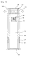
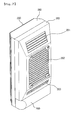
Fig. 13 is a front view of the state display part
according to the present invention and Fig. 14 is a
perspective view showing an upper case of the state display
part.
Referring to Figs. 13 and 14, the state display part
of the present invention is protected by a lower case 310
and an upper case 320. Also, a PCB (Printed Circuit Board)
(not shown) on which an electric circuit of the state
display part is formed is settled in the inside of the lower
case 310. Also, an LCD (Liquid Crystal Display) window 330
for displaying an operational state of the second indoor
unit is settled on the upper side of the PCB 320. Also, the
PCB and the LCD window 330 are mutually connected, so that a
signal and information provided from the PCB 320 is
transferred to the LCD window 330 and a user can visually
check an operational state.
Also, an operation button 321 by which a user can
manually operate and a receiving part 322 through which a
user can control the operational state using a remote
controller are formed on the lower side of the PCB.
Also, the lower case 310 has a wire settling part 312
at the lower side of the PCB, and a wire 340 connected from
the PCB is put in the inside of the wire settling part 312.
Also, a wire passing groove 314 through which the wire 340
passes is formed on the lateral side of the wire settling
part 312.
Also, a coupling part 311 extended with a
predetermined length and a coupling groove 311 penetrated on
a predetermined position of the coupling part are provided
on the upper side and/or the lower side of the lower case
310. More specifically, a coupling member is inserted in a
passing-through manner into the coupling groove 311 and the
state display part mounting boss 230 formed on the front
frame 280. Also, at least one hook 313 for joining to the
upper case 320 are formed on the outer periphery of the
lower case 310.
Also, at least one hook insertion hole 331 for
inserting into the upper side of the lower case 310 and
receiving the hook 313 on the outer periphery is formed on
the upper case 320. Also, an LCD window settling hole 332 to
which the LCD window 330 is fit is provided to the central
part.
In the meantime, the LCD window 330 displays the
operational state of the second indoor unit 200, and more
specifically, displays an amount of cool air discharged from
the second indoor unit 200, an indoor temperature and
humidity, and an operation time. Also, the state display
part 300 receives a radio wave sent through a remote
controller by a user, to display relevant information on the
LCD window 330 in a digital manner, depending on the
changing operational state. More specifically, the
displaying manner may be realized by a number and may also
by realized by an equalizer manner.
Fig. 15 is a view showing an operation of the display
part according to the present invention. Referring to Fig.
15, the display part 350 of the present invention outputs a
character image desired by a user or stored in advance in a
storage medium of the apparatus. The display part 350 formed
on the second indoor unit 200 may output an image realized
in the same operation manner as the character image
displayed on the display part 160.
More specifically, the display part 350 may include:
a case 351; a PCB 352 settled on the inside of the case 351;
an LCD window 353 settled on the upper part of the PCB 352;
an operation button 355 formed on the lower end of the PCB
352 so that not only a user may manually operate the display
part 350 and but also the operational state of the second
indoor unit 200 may be automatically run depending on a set
environment; and a wireless receiving part 357 for receiving
an operation signal transmitted through a remote controller
710 by a user and receiving an AVATA-transmitting signal
sent through a mobile means 700 such as a cellular phone by
a user. Also, a selection button 356 for setting or
selecting a plurality of kinds of AVATAs, is additionally
provided. Also, the display part 350 is connected with a
data inputting apparatus 720 as exemplified by a computer,
so that various kinds of characters can be downloaded
through the Internet.
Also, the display part 350 can be programmed in such
a way that a current operational state of the indoor unit
and a temperature may be announced in a voice at the same
time a character may be displayed on the LCD window 353.
Also, the voice is configured to guide the operational state
of the second indoor unit 200 in a human voice through a
speaker 730 connected with the controller.
Also, a memory chip 354 of a predetermined capacity,
capable of receiving and storing the AVATA character sent by
a user, may be built in the PCB 352. More specifically,
various kinds of character images existing in form of an
electronic file may be downloaded through the data inputting
apparatus 720 connected with the controlling part of the air
conditioner or the display part 350, and may be stored in
the memory chip 354.
Also, the character downloaded through the mobile
means 700 such as a cellular phone by a user, may be
received in a radio way by the receiving part 357 and stored
in the memory chip 354. Further, a user may produce, in
person, a character image of a proper shape using the data
inputting apparatus 720 and store the same in the memory
chip 354. As a result, for a means by which a user can
input/store/select a character, more than one among a
selection button 356 of an air conditioner itself, a remote
controller 710, a data inputting apparatus 720, a mobile
means 700, can be selectively used.
Also, in case the second indoor unit 200 is connected
and controlled as described above by the data inputting
apparatus 720 and/or the mobile means 700, the operational
state of the air conditioner can be controlled from a
remotely located area. Therefore, a user can control the air
conditioner system including the second indoor unit 200 to
operate through the Internet while a user is out, and
control the operation of the second indoor unit 200 using a
wireless telephone. Also, a user can use the display part
350 for an Internet screen as well as a means for showing
the operational state of the second indoor unit 200, by
connecting the display part 350 with the Internet. In other
words, the Internet screen is displayed by pressing the
selection button 356 of the display part 350, so that the
display part 350 can be used as a means for watching a news.
In the meantime, as described above, it will be
obvious to those skilled in the art that the apparatus for
controlling the operational state of the second indoor unit
200 through the Internet and the wireless communication
means, can be mounted on the state display part 300. Also,
it will be apparent from the spirit of the present invention
that the joining manner of the state display part 300 can be
applied, in the same way, to the manner in which the display
part 350 is settled on the case and joined to the front
frame 280.
The operational state of the display part will now be
described in the following.
On the first place, if a user transmits an operation
signal by pressing, in person, the operation button 355 or
through the remote controller 710 and the receiving part 357
receives the operation signal, the second indoor unit 200
operates. Also, the moment the second indoor unit 200
operates, a power source is applied to the display part 350
and a specific character image stored in advance or input by
a user, is displayed. For example, it is possible to have a
character that have been sleeping wakes up. Also,
simultaneously, it is possible to inform the operation of
the second indoor unit 200 with a voice through the speaker
730 connected with the display part 350. Also, the voice may
be downloaded through the mobile means 700 or the data
inputting apparatus 720, or recorded and stored in the
memory chip 354 by a user in person.
Also, while an amount of air, an indoor temperature,
humidity, an operation time are displayed on the state
display part 300, the character may perform a proper gesture
depending on an amount of air, an indoor temperature,
humidity, or a voice informing such information may be
announced through the speaker 730. For example, a user can
set in such a way that if a present temperature is below the
proper temperature programmed in advance, the character may
perform a gesture shivering with cold, and simultaneously, a
guiding message informing that the indoor temperature is too
low may be announced through the speaker. Also, if the
second indoor unit 200 is turned off, the character may
perform a gesture falling asleep and a guiding message
informing that the operation of the second indoor unit 200
is stopped may be announced through the speaker 730.
Also, a user may arbitrarily select the kind of the
AVATA using the selection button 356.
Fig. 16 is a block diagram explaining a control state
of the air conditioner according to the present invention.
Referring to Fig. 16, there are provided a key
inputting part 31 with which a control state of the air
conditioner is operated by a user; a power source part 32
for applying a power source to the air conditioner; an data
inputting apparatus 33 for inputting a specific character
and a plurality of character images using the character, to
the air conditioner; a controlling part 30 where a control
state of the air conditioner is stored in a storing medium
formed in the inside of the air conditioner and for
controlling the operation of the air conditioner using the
input information; an operational state display part 34 on
which at least character image is displayed under the
control of the controlling part 30; a voice outputting part
35 for outputting the operational state of the air
conditioner in a voice under the control of the controlling
part 30; a fan operating part 36 for controlling the
operational state of the outdoor unit and/or the indoor
unit, under the control of the controlling part 30; and a
compressor operating part 37 for circulating a coolant.
More specifically, the key inputting part 31, which is
a part with which a user operates the operational state of
the air conditioner, may be at least one selected among a
remote controller of the air conditioner, a button formed on
the appearance of the apparatus, a computer system connected
through wiring/wireless network. Also, the data inputting
part 33 is a device for generating or downloading a
character and a plurality of character images where the
specific character appears and transferring the same to the
controlling part 30. For such a data inputting part 33, at
least one among a computer, a mobile means, a remote
controller, may be used.
Also, the operational state display part 34 formed on
the air conditioner, preferably, a predetermined outer side
of the indoor unit, is a part through which the operational
state of the air conditioner may be displayed to a user in
an easy and simple manner with the character image
displayed. Preferably, the operational state display part 34
is realized by the LCD so that a user may recognize the
character image in a convenient and beautiful manner.
By displaying, as describe above, the character image
on the operational state display part 34, a user can
recognize the operational state of the air conditioner in a
more easy and convenient manner. Particularly, since a shape
of the character image changes depending on the operational
state of the air conditioner, a user can recognize the
operational state of the air conditioner in even more easy
and convenient manner.
Also, the voice outputting part 35, which is a part
for outputting the operational state of the air conditioner
in form of a voice, can output the operational state of the
air conditioner in form of a voice depending on a user's
desire.
Also, the fan operating part 36 and the compressor
operating part 37, which are apparatus for circulating a
coolant in the inside of the cooling cycle to get a coolant
to pass through processes of compression, condensation,
expansion, and evaporation in accordance with the
operational state by a user, are on/off-controlled by the
controlling part 30 depending on the operational state and
the indoor temperature of the air conditioner.
The operation of the air conditioner will be briefly
described with reference to the block diagram of the
described air conditioner system. The air conditioner system
of the present invention can be operated in three modes. A
first mode is a character image uploading mode for uploading
a character image into the controlling part 30 in the inside
of the air conditioner using the data inputting part 33. A
second mode is a character image display mode where the air
conditioner system is operated by operation of the key
inputting part 31 by a user and the character image is
displayed on the operational state display part 34. A third
mode is a character and a character image selecting mode for
selecting a set of character images related to a specific
character.
As described above, by making the kind of the
character image changed depending on the operational state
of the air conditioner, the recognition of a user can be
convenient even more. Also, since a specific character is
selected in accordance with a taste of a user and a specific
set of character images can be selected among a plurality of
character images where the character is used, a user can
display a character fit for a user's taste, on the air
conditioner in a convenient manner. For an extreme example,
a user's picture may be displayed.
In the meantime, the character and the character image
selecting mode is easily performed by cooperative operation
of the key inputting part 31 and the controlling part 30.
More specifically, after the process for selecting a
character is performed, a specific character image is
selected among a plurality of character images related to
the selected character, for each operational state of the
air conditioner. Of course, if a user desires, a specific
character needs not to be used in a related set, for each
operational state of the air conditioner, and other
character image where other character is used, may be set
for each operational state of the air conditioner.
Therefore, the character image uploading mode and the
character image display mode will be described in detail in
the following.
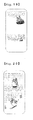
Fig. 17 is a flowchart explaining the character image
uploading mode according to the spirit of the present
invention.
Referring to Fig. 17, a user obtains a character
and/or a character image by downloading through a network or
by producing, in person, the character image (S11). For the
process in which the character is generated, any type of
method such as wiring/wireless network and a producing by a
user, may be used without limitations. Of course, when the
air conditioner is brought to the market, a plurality of
characters, a plurality of character images where a pose, a
background, a position, and a movement are different for
each character, may be stored in a set in the storing medium
in the inside of the controlling part 30.
Afterwards, a user uploads the generated character
image to the controlling part 30 through the data inputting
part 33 (S12). The uploading process can be easily performed
through a LAN (Local Area Network) and wiring/wireless
Internet. The character and the character image uploaded in
this manner, are stored in the storing medium of the
controlling part 30 (S13), and upon calling by a user, one
set of character images to which a specific character is
applied, is called and used in the air conditioner.
Fig. 18 is a flowchart explaining the character image
display mode of the air conditioner to which the spirit of
the present invention is applied.
Referring to Fig. 18, the operation of the air
conditioner is started by an input or reservation setting of
a user (S21). If the operation of the air conditioner is
started, one set of character images selected in advance by
a user is called and a character image appropriate for a
present state, initial operation of the air conditioner, is
displayed on the operational state display part 34 on the
first place (S22). If a selected character is absent at the
present point of time, selection of a character may be
automatically requested on the first place, or one set of
character images designated from the time of manufacturing
of the air conditioner, may be called.
Afterwards, it is judged whether the operational state
of the air conditioner is changed while the operation of the
air conditioner is continuously performed (S23). If the
operational state of the air conditioner is changed, a new
character image appropriated for the changed operational
state of the air conditioner among the called one set of
character images, is automatically displayed in accordance
with the changed operational state of the air conditioner
(S24). If the operational state of the air conditioner is
not changed, the character image of the present state is
continuously displayed.
If the operation of the air conditioner is ended while
the new changed character image is displayed, a character
image of ended state is displayed (S26) and the operation of
the air conditioner is ended. However, if the operation of
the air conditioner is not ended, the process is moved to
the step of judging a change of the operational state of the
air conditioner (S23), and the process for changing the
character image is repeated until the air conditioner is
ended.
In case a user sets a specific character image in
advance, for each operational state of the air conditioner,
in performing the character image display mode as described
above, not only the character image included in one set
related to a single character but also another character
image where another character is used, may be displayed for
each operational state of the air conditioner in accordance
with a taste of a user.
With a Whini, character that will be set in advance in
the storing medium of the product, taken as an example,
changing of the character image according to the gesture,
the pose, the position, and the background will be described
in the following.
Fig. 19 shows a character image displayed in the
start/stop mode of the operation of the air conditioner.
Referring to Fig. 19, upon starting of the operation,
the character image moving from the lower side to the upper
side is displayed. On the contrary, upon ending of the
operation, the character image moving from the character
image on the upper side to the character image on the lower
side, is displayed on the operational state display part 34.
Fig. 20 shows a character image displayed in the
cooling operation mode of the air conditioner. Referring to
Fig. 20, upon the general cooling operation, the character
image on the upper side is displayed and upon a power
cooling operation, the character image on the lower side is
displayed.
Fig. 21 shows a character image displayed in the
dehumidifying operation mode of the air conditioner.
Referring to Fig. 21, upon the dehumidifying operation mode,
the character images on the upper side and on the lower side
are alternately displayed.
Fig. 22 shows a character image displayed in the
artificial intelligence operation mode of the air
conditioner. Referring to Fig. 22, upon the artificial
intelligence operation mode, the character images on the
upper side and on the lower side are alternately displayed.
Fig. 23 shows a character image displayed in the
plasma clean operation mode of the air conditioner.
Referring to Fig. 23, upon the plasma clean operation mode,
the character images on the upper side and on the lower side
are alternately displayed.
As shown in the character images exemplified by Figs.
19 to 23, even under the state that the same character
appears as a major character, the character image displayed
on the operational state display part 34 is varied in detail
in accordance with the change of the operational state of
the air conditioner. Since the displayed character is
changed in this manner, a user can check the operational
state of the air conditioner in a more easy manner. Also, by
the display parts 160 and 350 formed on the front of the air
conditioner, the air conditioner can be quality-enhanced and
a taste of a user can be satisfied even more.
Further, in case the character and the character image
are set differently for each operational state of the air
conditioner according to a taste of a user, there is a
strong point that even the same air conditioner can be used
for a long time as if it were a new apparatus.
Second Embodiment
The second embodiment of the present invention is the
same in most part as the first embodiment. Only difference
is that the display parts 160 and 350 on which at least a
character image is displayed and the state display parts 170
and 300 on which the operational state of the air
conditioner is displayed with a number or an arrow, are not
formed separately but one or both two are displayed on a
single LCD window by a selection of a user.
More specifically, in the first embodiment, the
display parts 160 and 350, and the state display parts 170
and 300 are separately formed on both the first indoor unit
100 and the second indoor unit 200. However, in that case,
since the wide area on the front side of the indoor unit is
occupied, it is not preferable in viewpoints of costs and
use. Therefore, there is provided a method where a state
that a character image is selectively displayed on a single
display part by a selection of a user (for example, the
display part of the first embodiment), or a state that the
operational state of the air conditioner is displayed with
letters (for example, the state display part of the first
embodiment), are selectively displayed or both state are all
displayed with use of the characteristics of the LCD where
various screen configuration is possible.
Figs. 24 and 25 show the operational state of the
display part. Fig. 24 shows that the character image is
displayed on the display part and FIG. 25 shows the
operational state of the air conditioner is displayed on the
display part.
Referring to Figs. 24 and 25, there are provided a
front panel 810 formed on a front of the air conditioner; a
side panel 820 formed on the side of the air conditioner; a
display window 860 formed on the front panel 810; an
operation button 880 formed on one side of the display
window 860, for operating the operational state of the air
conditioner; a selection button 871 formed on the other side
of the display window 860, for switching a screen displayed
on the display window 860, into a display part where a
character image is displayed or a state display part where
the operational state of the air conditioner is displayed
with letters; and a character setting button 872 for
selecting the kind of a character or the kind of a character
image. Also, for the display window 860, the LCD is
preferably used as the first embodiment.
For other parts of the present embodiment, the
descriptions made for the first embodiment are quoted.
Particularly, the selection button 871 will be described in
detail. By a number of times the selection button 871 is
pressed, the display window 860 operates as the display part
861 where the character image is displayed (refer to FIG.
24) or operates as the state display part 862 where the
operational state of the air conditioner is displayed with
letters (refer to FIG. 25). Of course, it will be easily
estimated that both the display part 861 and the state
display part 862 can be all displayed.
Also, it is possible to have a specific kind of
characters and a specific kind of character images selected
if the character setting button 872 is pressed. Also, in
case a plurality of character setting buttons 872 is
provided, a button for selecting a character and a button
for selecting a character image can be separately provided,
for each kind of buttons. Particularly, though not described
in the first embodiment, the character setting button 872
will be easily realized also in the first embodiment. Also,
if the character setting button 872 is not provided, the
kind of the character and the kind of the character image
may be easily selected together with the gesture input from
the data inputting part 33.
Mode for invention
The present invention is characterized in that a
predetermined display window is realized on the front of the
air conditioner and a character image in which a
predetermined character image is used, is displayed on the
display window. Also, the present invention is characterized
in that a user can use the air conditioner in a more
convenient manner thanks to the character and the character
image related to the character.
Within the range satisfying the above characteristics,
the air conditioner capable of improving the user's
recognizability according to the present invention, can have
various form in its embodiments.
On the first place, in case two indoor units are not
used but a single indoor unit is used in a single outdoor
unit, an effect that a user's convenience is improved can be
obtained by realizing, on the single indoor unit, a display
window on which a character and/or a character image is
displayed.
Also, the spirit of the present invention can be
applied not only to the air conditioner that has been
described by the detailed embodiment, but also to other
electronic appliances such as a cooking apparatus and a
refrigerator, with change in its form in a convenient
manner. At this time, with the character maintained as it
is, the operational state of the air conditioner can be
displayed by changing a pose, a position, a background, and
a behavior of the character.
Also, even though the apparatus and/or method for
inputting, selecting, or setting a character and a character
image may be changed depending on detail use conditions,
such changes will not influence on realization of the spirit
of the present invention.
Also, for the character image displayed on the display
part, not only the character image where the character is
used, but also a character of a representative shape may be
constantly displayed regardless of the operational state of
the air conditioner. In case of the air conditioner, it will
be preferable that a character that can emphasize coolness
such as a penguin is selected.
It will be apparent to those skilled in the art that
various modifications and variations can be made in the
present invention. Thus, it is intended that the present
invention covers the modifications and variations of this
invention provided they come within the scope of the
appended claims and their equivalents.
Industrial Applicability
According to the spirit of the present invention, a
character image understandable as the relevant operational
state depending on the operational state of the air
conditioner, is displayed on one side of the air
conditioner, so that a user can understand the operational
state of the air conditioner in a convenient manner, without
looking at the state display part displayed with letters.
Also, the present invention uses a character of a
beautiful design besides the state display part displayed
with letters of the conventional stiff image, thereby
possibly obtaining more better visual effect. Accordingly, a
user's taste can be promoted even more.
Also, according to the present invention, a user can
produce, in person, a character desired by a user, obtain
various characters and character images where the character
is used through various communication media, store in the
storing medium in the inside of the air conditioner, and use
the same. Therefore, since a user who makes use of the air
conditioner can newly display a new character and/or a new
character image at any time when a user desires or is tired
of the existing character, the present invention has an
effect that a user can use the air conditioner for a more
longer time and a user can the air conditioner as if it were
a newly purchased apparatus at any time when a user desires.
Also, the present invention additionally includes a
voice outputting part for displaying the operation of the
air conditioner, so that a voice message is properly output
for each operational state of the air conditioner.
Therefore, there is a strong point that a remotely located
user or even the blind can use the air conditioner in a more
convenient manner.
Also, in case the same character is used for the
entire items of the electronic appliances manufactured by a
single company, the character as a trademark can enhance a
brand image of the manufacturing company and in case the
character is used for an advertising means, the character
can function as a means for obtaining advertisement profit.