EP1589274A1 - Strömungsakustisch optimierte Rohrleitungen - Google Patents
Strömungsakustisch optimierte Rohrleitungen Download PDFInfo
- Publication number
- EP1589274A1 EP1589274A1 EP05008238A EP05008238A EP1589274A1 EP 1589274 A1 EP1589274 A1 EP 1589274A1 EP 05008238 A EP05008238 A EP 05008238A EP 05008238 A EP05008238 A EP 05008238A EP 1589274 A1 EP1589274 A1 EP 1589274A1
- Authority
- EP
- European Patent Office
- Prior art keywords
- conduit
- damping means
- vibration
- damped
- pipeline
- Prior art date
- Legal status (The legal status is an assumption and is not a legal conclusion. Google has not performed a legal analysis and makes no representation as to the accuracy of the status listed.)
- Granted
Links
- 238000013016 damping Methods 0.000 claims abstract description 44
- 239000012530 fluid Substances 0.000 claims abstract description 28
- OKTJSMMVPCPJKN-UHFFFAOYSA-N Carbon Chemical compound [C] OKTJSMMVPCPJKN-UHFFFAOYSA-N 0.000 claims abstract description 9
- 230000005540 biological transmission Effects 0.000 claims abstract description 8
- 229920002457 flexible plastic Polymers 0.000 claims abstract 2
- 229920003023 plastic Polymers 0.000 claims description 9
- 230000001419 dependent effect Effects 0.000 claims description 2
- 229910052799 carbon Inorganic materials 0.000 abstract 1
- 239000000463 material Substances 0.000 description 6
- 238000004519 manufacturing process Methods 0.000 description 3
- 230000010349 pulsation Effects 0.000 description 3
- 239000003795 chemical substances by application Substances 0.000 description 2
- 230000000694 effects Effects 0.000 description 2
- 238000005452 bending Methods 0.000 description 1
- 238000010276 construction Methods 0.000 description 1
- 238000011161 development Methods 0.000 description 1
- 230000018109 developmental process Effects 0.000 description 1
- 239000007788 liquid Substances 0.000 description 1
- 230000003584 silencer Effects 0.000 description 1
- 238000009736 wetting Methods 0.000 description 1
Images

Classifications
-
- F—MECHANICAL ENGINEERING; LIGHTING; HEATING; WEAPONS; BLASTING
- F16—ENGINEERING ELEMENTS AND UNITS; GENERAL MEASURES FOR PRODUCING AND MAINTAINING EFFECTIVE FUNCTIONING OF MACHINES OR INSTALLATIONS; THERMAL INSULATION IN GENERAL
- F16L—PIPES; JOINTS OR FITTINGS FOR PIPES; SUPPORTS FOR PIPES, CABLES OR PROTECTIVE TUBING; MEANS FOR THERMAL INSULATION IN GENERAL
- F16L55/00—Devices or appurtenances for use in, or in connection with, pipes or pipe systems
- F16L55/02—Energy absorbers; Noise absorbers
- F16L55/033—Noise absorbers
- F16L55/0331—Noise absorbers by inserting an elongated element in the pipe
Definitions
- the invention relates to a flow-acoustically optimized pipe comprising a flexible conduit and damping means to reduce sound transmission through the conduit flowing through, substantially gaseous fluid, in particular in a motor vehicle.
- Such sound-damped piping usually come in Motor vehicles or machines are used in which man in the immediate vicinity of the machine acts. Especially Such soundproofed pipelines are used in motor vehicles used.
- the invention includes the technical teaching that in the arranged through-flow conduit inner space of the conduit Damping means are flowed through, to a swirling to cause the flowing through fluid, so that through reduces the transmitted fluid transmitting vibrations become.
- the conduit is formed as a plastic tube, which is used in a motor vehicle and
- a tank vent valve with an activated carbon filter connects and / or between engine and body is arranged. From the tank vent valve respectively by gas vibrations in the intake tract a pulsation is emitted, which clearly in the passenger compartment of the motor vehicle and in the vicinity of the motor vehicle through there Person is perceptible.
- a pipeline according to the invention dampens the transmitted acoustic signal, making it suitable for in the Passenger compartment and located in the immediate vicinity of the motor vehicle Persons is not perceived.
- Plastic pipes due to their low weight for use. These plastic pipes are also thin-walled to Save weight and around the pipe a certain To give flexibility.
- plastic pipe has a smooth inner pipe wall has, since it so low friction losses between the fluid and the conduit inner wall comes.
- Plastic pipes with a smooth inner wall are the most common plastic pipes, so these in all sizes and Molds for use in a motor vehicle are present and so used without major manufacturing or processing effort can be.
- the invention is also suitable for pulsation in rigid tubes and other materials.
- damping means as in essence wave-shaped and / or spiral band is formed, which a defined number of spirals respectively Has waves, wherein the helices or waves with a defined gradient or a defined Wavelength are formed, creating a defined turbulence of the flowing fluid can be generated.
- the damping means is a substantially geometric having defined cross section, comprising elliptical, oval and rectangular geometries or cross sections.
- the Cross sections for manufacturing reasons, however, simple Geometries, like the examples listed above.
- This elliptical cross section allows a easy production of the damping agent with a high stability and low flow resistance, so that optimal Noise damping or reduced sound transmission is realized.
- the damping means of a plastic is manufactured, which has substantially the same characteristics has, as the material of the surrounding pipe. In principle, however, other materials can be used.
- the damping means is substantially coaxial with Conduit arranged.
- the damping means becomes easy introduced into the conduit without the damping means is attached to the conduit inner wall. Due to the dimensions, in particular the outer dimensions, of the damping means, which in about the inner dimensions of the conduit correspond, that is Damping means approximately centrally or more precisely coaxially in the conduit. Characterized in that the damping means coaxial with the conduit can be arranged, the top and bottom of the spiral wound damping means simultaneously on the flowing fluid act and so optimal turbulence to Reduction of the sound attenuation effect.
- the damping means in each case to the specific use to optimize. Numerous experiments have shown that that the number of coils or waves that Length of the damping means, the total length of the pipe and the Slope or the wavelength are tuned. For example, the number of coils or waves the damping means depending on the in the axial direction to the Tuned longitudinal axis measured total length of the pipe is.
- Turbulator trained turbulence generator in a conduit for swirling the fluid flowing through and thus for reducing the sound transmitted by the fluid use, for example, the conduit between engine and body or between a tank vent valve and an activated carbon filter is arranged.
- turbulence generators such as Use turbulators.
- Use turbulators These are already in Lines for substantially liquid fluids for improvement the wetting of the inner wall of the pipe is used, resulting in a significantly increased heat exchange between tube and fluid achieve.
- a use as a silencer for pipes, the flowing through a gaseous fluid is however new, whereby the turbulator used and the line length correspond must be trained for optimal noise reduction to enable.
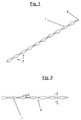
- the damping means 1 of FIG. 1 is considered to be substantially spiral or wave-shaped band or as a spiral or wavy strip of material educated.
- the material strip in In the longitudinal direction of a central axis 2, to the material strip or the band or generally the damping means 1 wound or wavy.
- the coils 3 or waves By the elliptical Cross-section of the damping means 1 caused by the distortion or bending about the longitudinal axis 2 so-called Spiral 3 or waves, the coils 3 or waves a gradient or a Have wavelength.
- the coils 3 and waves are evenly distributed over the damping means in the axial direction.
- Fig. 2 the damping means 1 in a side view shown.
- the coils 3 Schematically the gradient ⁇ of a helix 3 is shown. You realize that the coils 3 are substantially uniform with one substantially same pitch ⁇ arranged over the damping means 1 are.
- FIG. 3 schematically shows a flow-acoustically optimized, flexible pipe 4 comprising a conduit 5 with a Conduit interior 6, of a conduit inner wall 7 is limited and approximately centrally in the conduit 5, more precisely the conduit inner space 6 arranged damping means 1 in Cross section shown.
- the cross section of the conduit 5, more precisely, the conduit inner space 6 is circular, the cross section of the damping means 1 elliptical, wherein the elliptical cross-sectional area of the damping means 1 in approximately centered to the circular cross-sectional area of the conduit interior 6 is arranged in the conduit 5, that is the centers of the cross-sectional geometry of the damping means 1 and the pipe interior 6 are substantially congruent.
- the damping means 1 is tangent to the conduit inner wall 7 each with the farthest from the longitudinal axis Surface, whereby the conduit inner space 6 in two pipe sections is divided. Through contact with the Conduit inner wall 7, the damping means 1 is approximately in the Center of the conduit inner space 6, wherein the damping means 1 loose in the manner of a clearance fit is stored. This arrangement creates a through the structure of the Damping agent 1 caused by the turbulence Conduit 5 and flowing through the pipe 4 Fluid.
Landscapes
- Engineering & Computer Science (AREA)
- General Engineering & Computer Science (AREA)
- Mechanical Engineering (AREA)
- Pipe Accessories (AREA)
- Exhaust Silencers (AREA)
Abstract
Description
- Fig. 1
- eine perspektivische Ansicht eines Dämpfungsmittels,
- Fig. 2
- eine Seitenansicht eines Ausschnitts des Dämpfungsmittels nach Fig. 1 und
- Fig. 3
- eine schematische Darstellung der Anordnung des Ausschnitts des Dämpfungsmittels nach Fig. 1 in einer Rohrleitung.
- 1
- Dämpfungsmittel
- 2
- Längsachse
- 3
- Wendel
- 4
- Schwingungsakustisch optimierte Rohrleitung
- 5
- Leitungsrohr
- 6
- Leitungsrohrinnenraum
- 7
- Leitungsrohrinnenwand
- α
- Steigungsgrad
Claims (10)
- Strömungsakustisch optimierte Rohrleitung (4) umfassend ein Leitungsrohr (5) und Dämpfungsmittel (1) zur Reduzierung einer Schallübertragung durch ein das Leitungsrohr (5) durchströmendes, im Wesentlichen gasförmiges Fluid, insbesondere in einem Kraftfahrzeug, dadurch gekennzeichnet, dass die in dem durchströmbaren Leitungsrohrinnenraum (6) des Leitungsrohrs (5) angeordneten Dämpfungsmittel (1) undurchströmbar sind, um eine Verwirbelung des durchströmenden Fluids zu bewirken, so dass die durch das durchströmende Fluid übertragende Schwingungen reduziert sind.
- Schwingungsgedämpfte Rohrleitung (4) nach Anspruch 1, dadurch gekennzeichnet, dass das Leitungsrohr (5) als ein flexibles Kunststoffrohr ausgebildet ist, welches ein Tankentlüftungsventil mit einem Aktivkohlefilter verbindet und/oder zwischen Motor und Karosserie angeordnet ist.
- Schwingungsgedämpfte Rohrleitung (4) nach Anspruch 1 oder 2, dadurch gekennzeichnet, dass das Kunststoffrohr eine glatte Leitungsrohrinnenwand (7) aufweist.
- Schwingungsgedämpfte Rohrleitung (4) nach einem der vorherigen Ansprüche, dadurch gekennzeichnet, dass das Dämpfungsmittel (1) als im Wesentliches wellenförmiges und/oder spiralförmiges Band ausgebildet ist, welches eine definierte Anzahl von Wendeln (3) beziehungsweise Wellen aufweist, wobei die Wendeln (3) beziehungsweise Wellen mit einem definierten Steigungsgrad (α) beziehungsweise Wellenlänge ausgebildet sind, wodurch eine definierte Verwirbelung des durchströmenden Fluids erzeugbar ist.
- Schwingungsgedämpfte Rohrleitung (4) nach einem der vorherigen Ansprüche, dadurch gekennzeichnet, dass das Dämpfungsmittel (1) einen im Wesentlichen geometrisch definierten Querschnitt aufweist, umfassend elliptische, ovale und rechteckige Geometrien.
- Schwingungsgedämpfte Rohrleitung (4) nach einem der vorherigen Ansprüche, dadurch gekennzeichnet, dass das Dämpfungsmittel (1) aus einem Kunststoff hergestellt ist, der im Wesentlichen den Eigenschaften des umgebenden Leitungsrohrs (5) entspricht.
- Schwingungsgedämpfte Rohrleitung (4) nach einem der vorherigen Ansprüche, dadurch gekennzeichnet, dass das Dämpfungsmittel (1) im Wesentlichen koaxial zum Leitungsrohr (5) angeordnet ist.
- Schwingungsgedämpfte Rohrleitung (4) nach einem der vorherigen Ansprüche, dadurch gekennzeichnet, dass die Anzahl der Wendeln (3) beziehungsweise Wellen abhängig von der in axialer Richtung zu der Längsachse (2) gemessenen Gesamtlänge des Leitungsrohrs (5) ist.
- Schwingungsgedämpfte Rohrleitung (4) nach einem der vorherigen Ansprüche, dadurch gekennzeichnet, dass der Steigungsgrad (α) beziehungsweise die Wellenlänge der Wendel (3) beziehungsweise der Wellen abhängig von der in axialer Richtung zu der Längsachse (2) gemessenen Gesamtlänge des Leitungsrohrs (5) ist.
- Verwendung eines als Turbulator ausgebildeten Turbulenzgenerators in einem Leitungsrohr (5) zur Verwirbelung des durchströmenden Fluids und damit zur Reduzierung des durch das Fluid übertragenen Schalls.
Applications Claiming Priority (2)
| Application Number | Priority Date | Filing Date | Title |
|---|---|---|---|
| DE102004020094A DE102004020094A1 (de) | 2004-04-24 | 2004-04-24 | Strömungsakustisch optimierte Rohrleitungen |
| DE102004020094 | 2004-04-24 |
Publications (2)
| Publication Number | Publication Date |
|---|---|
| EP1589274A1 true EP1589274A1 (de) | 2005-10-26 |
| EP1589274B1 EP1589274B1 (de) | 2012-01-18 |
Family
ID=34935209
Family Applications (1)
| Application Number | Title | Priority Date | Filing Date |
|---|---|---|---|
| EP05008238A Expired - Lifetime EP1589274B1 (de) | 2004-04-24 | 2005-04-15 | Kraftfahrzeug mit einer strömungsakustisch optimierten Rohrleitung |
Country Status (3)
| Country | Link |
|---|---|
| EP (1) | EP1589274B1 (de) |
| AT (1) | ATE542083T1 (de) |
| DE (1) | DE102004020094A1 (de) |
Cited By (1)
| Publication number | Priority date | Publication date | Assignee | Title |
|---|---|---|---|---|
| WO2010130903A1 (fr) | 2009-05-13 | 2010-11-18 | Renault Sas | Boucle de climatisation d'un vehicule automobile comportant une chambre d'expansion de volume |
Citations (4)
| Publication number | Priority date | Publication date | Assignee | Title |
|---|---|---|---|---|
| DE609890C (de) * | 1932-03-09 | 1935-02-26 | Hugo Kosmack | Wendelrohre |
| US3313577A (en) * | 1965-03-15 | 1967-04-11 | Wolfe Samuel Edmund | Method and apparatus for transporting slurries |
| EP0077130A1 (de) * | 1981-10-13 | 1983-04-20 | Mihama Manufacturing Co., Ltd. | Vorrichtungen zur Turbulenzerzeugung |
| US5443371A (en) * | 1994-12-12 | 1995-08-22 | Tecumseh Products Company | Noise damper for hermetic compressors |
Family Cites Families (4)
| Publication number | Priority date | Publication date | Assignee | Title |
|---|---|---|---|---|
| FR1153298A (fr) * | 1955-05-11 | 1958-03-04 | Silencieux | |
| SE177601C1 (sv) * | 1955-05-11 | 1961-12-19 | J R Andersson & Co A B | Ljuddämpare för strömmande gaser |
| DE1873845U (de) * | 1963-02-13 | 1963-06-12 | Richard Thienhaus | Schalldaempfer. |
| US3696883A (en) * | 1971-12-13 | 1972-10-10 | Harry M Devane | Sound muting assembly for gas flow duct systems |
-
2004
- 2004-04-24 DE DE102004020094A patent/DE102004020094A1/de not_active Withdrawn
-
2005
- 2005-04-15 AT AT05008238T patent/ATE542083T1/de active
- 2005-04-15 EP EP05008238A patent/EP1589274B1/de not_active Expired - Lifetime
Patent Citations (4)
| Publication number | Priority date | Publication date | Assignee | Title |
|---|---|---|---|---|
| DE609890C (de) * | 1932-03-09 | 1935-02-26 | Hugo Kosmack | Wendelrohre |
| US3313577A (en) * | 1965-03-15 | 1967-04-11 | Wolfe Samuel Edmund | Method and apparatus for transporting slurries |
| EP0077130A1 (de) * | 1981-10-13 | 1983-04-20 | Mihama Manufacturing Co., Ltd. | Vorrichtungen zur Turbulenzerzeugung |
| US5443371A (en) * | 1994-12-12 | 1995-08-22 | Tecumseh Products Company | Noise damper for hermetic compressors |
Cited By (1)
| Publication number | Priority date | Publication date | Assignee | Title |
|---|---|---|---|---|
| WO2010130903A1 (fr) | 2009-05-13 | 2010-11-18 | Renault Sas | Boucle de climatisation d'un vehicule automobile comportant une chambre d'expansion de volume |
Also Published As
| Publication number | Publication date |
|---|---|
| DE102004020094A1 (de) | 2005-11-17 |
| EP1589274B1 (de) | 2012-01-18 |
| ATE542083T1 (de) | 2012-02-15 |
Similar Documents
| Publication | Publication Date | Title |
|---|---|---|
| EP1030965B1 (de) | Gasdurchströmte leitung mit schallabsorptionswirkung | |
| DE102013223992B4 (de) | Universelle Dämpfungseinrichtung für einen Klimatisierungskreislauf | |
| DE112009005180B4 (de) | Abgasvorrichtung für eine Verbrennungskraftmaschine | |
| EP2357330A1 (de) | Schalldämpfer für einen rohrförmigen einen Hohlraum bildenden Körper | |
| US8505678B2 (en) | Fluid transfer pipe and fluid transfer apparatus and a fluid attenuator and attenuator apparatus | |
| DE102006050869A1 (de) | Schalldämpfungseinrichtung für eine Luftrohrleitung eines Flugzeuges, insbesondere bei einer Flugzeugklimaanlage | |
| DE102010043267A1 (de) | Schalldämpfer für ein Lufteinlasssystem eines Verbrennungsmotors | |
| DE19504223A1 (de) | Schalldämpfer für den Ansaugkanal einer Brennkraftmaschine | |
| DE10121582C2 (de) | Luftversorgungs-Aggregat für Fahrzeuge mit einem Kompressor und einem Schalldämpfer | |
| DE102007007600A1 (de) | Schalldämpfer für eine Abgasanlage | |
| DE1292667B (de) | Schalldaempfer fuer stroemende Gase | |
| DE102007000793A1 (de) | Luftansaugvorrichtung | |
| DE2908506A1 (de) | Schalldaempfer fuer verbrennungskraftmaschinen | |
| EP1589274B1 (de) | Kraftfahrzeug mit einer strömungsakustisch optimierten Rohrleitung | |
| EP2446128A1 (de) | Rohrförmiges akustisches dämmelement | |
| EP1589273B1 (de) | Strömungsakustisch optimierte flexible Rohrleitung | |
| DE202007017661U1 (de) | Akustischer Schalldämpfer für Verbrennungsmotoren | |
| DE10219964B4 (de) | Hochfrequenzdämpfer | |
| EP1416148A2 (de) | Schallreduzierendes Bauteil für ein Luftführungsrohr | |
| DE2856889A1 (de) | Schalldaempfer in der abgasleitung eines verbrennungsmotors, insbesondere an einem kraftfahrzeug | |
| EP2567076B1 (de) | Breitbandig dämpfende vorrichtung zur schalldämpfung bei industrieeinrichtungen, grossanlagen oder maschinen | |
| DE6608356U (de) | Abgasanlage mit schalldaempfer. | |
| DE10243225A1 (de) | Schalldämpfer und Verfahren zu seiner Auslegung | |
| EP1500798B1 (de) | Schalldämpfer sowie Abgasanlage | |
| DE102022128270B3 (de) | Schallwellendrossel |
Legal Events
| Date | Code | Title | Description |
|---|---|---|---|
| PUAI | Public reference made under article 153(3) epc to a published international application that has entered the european phase |
Free format text: ORIGINAL CODE: 0009012 |
|
| AK | Designated contracting states |
Kind code of ref document: A1 Designated state(s): AT BE BG CH CY CZ DE DK EE ES FI FR GB GR HU IE IS IT LI LT LU MC NL PL PT RO SE SI SK TR |
|
| AX | Request for extension of the european patent |
Extension state: AL BA HR LV MK YU |
|
| 17P | Request for examination filed |
Effective date: 20060413 |
|
| AKX | Designation fees paid |
Designated state(s): AT BE BG CH CY CZ DE DK EE ES FI FR GB GR HU IE IS IT LI LT LU MC NL PL PT RO SE SI SK TR |
|
| RAP1 | Party data changed (applicant data changed or rights of an application transferred) |
Owner name: GM GLOBAL TECHNOLOGY OPERATIONS LLC |
|
| RTI1 | Title (correction) |
Free format text: AUTOMOTIVE WITH A FLOW-ACOUSTIC OPTIMIZED FLEXIBLE PIPE |
|
| GRAP | Despatch of communication of intention to grant a patent |
Free format text: ORIGINAL CODE: EPIDOSNIGR1 |
|
| GRAS | Grant fee paid |
Free format text: ORIGINAL CODE: EPIDOSNIGR3 |
|
| GRAA | (expected) grant |
Free format text: ORIGINAL CODE: 0009210 |
|
| AK | Designated contracting states |
Kind code of ref document: B1 Designated state(s): AT BE BG CH CY CZ DE DK EE ES FI FR GB GR HU IE IS IT LI LT LU MC NL PL PT RO SE SI SK TR |
|
| REG | Reference to a national code |
Ref country code: GB Ref legal event code: FG4D Free format text: NOT ENGLISH |
|
| REG | Reference to a national code |
Ref country code: CH Ref legal event code: EP |
|
| REG | Reference to a national code |
Ref country code: IE Ref legal event code: FG4D Free format text: LANGUAGE OF EP DOCUMENT: GERMAN Ref country code: AT Ref legal event code: REF Ref document number: 542083 Country of ref document: AT Kind code of ref document: T Effective date: 20120215 |
|
| REG | Reference to a national code |
Ref country code: DE Ref legal event code: R096 Ref document number: 502005012351 Country of ref document: DE Effective date: 20120315 |
|
| REG | Reference to a national code |
Ref country code: NL Ref legal event code: VDEP Effective date: 20120118 |
|
| LTIE | Lt: invalidation of european patent or patent extension |
Effective date: 20120118 |
|
| PG25 | Lapsed in a contracting state [announced via postgrant information from national office to epo] |
Ref country code: IS Free format text: LAPSE BECAUSE OF FAILURE TO SUBMIT A TRANSLATION OF THE DESCRIPTION OR TO PAY THE FEE WITHIN THE PRESCRIBED TIME-LIMIT Effective date: 20120518 Ref country code: BG Free format text: LAPSE BECAUSE OF FAILURE TO SUBMIT A TRANSLATION OF THE DESCRIPTION OR TO PAY THE FEE WITHIN THE PRESCRIBED TIME-LIMIT Effective date: 20120418 Ref country code: NL Free format text: LAPSE BECAUSE OF FAILURE TO SUBMIT A TRANSLATION OF THE DESCRIPTION OR TO PAY THE FEE WITHIN THE PRESCRIBED TIME-LIMIT Effective date: 20120118 Ref country code: LT Free format text: LAPSE BECAUSE OF FAILURE TO SUBMIT A TRANSLATION OF THE DESCRIPTION OR TO PAY THE FEE WITHIN THE PRESCRIBED TIME-LIMIT Effective date: 20120118 |
|
| REG | Reference to a national code |
Ref country code: IE Ref legal event code: FD4D |
|
| PG25 | Lapsed in a contracting state [announced via postgrant information from national office to epo] |
Ref country code: PT Free format text: LAPSE BECAUSE OF FAILURE TO SUBMIT A TRANSLATION OF THE DESCRIPTION OR TO PAY THE FEE WITHIN THE PRESCRIBED TIME-LIMIT Effective date: 20120518 Ref country code: GR Free format text: LAPSE BECAUSE OF FAILURE TO SUBMIT A TRANSLATION OF THE DESCRIPTION OR TO PAY THE FEE WITHIN THE PRESCRIBED TIME-LIMIT Effective date: 20120419 Ref country code: PL Free format text: LAPSE BECAUSE OF FAILURE TO SUBMIT A TRANSLATION OF THE DESCRIPTION OR TO PAY THE FEE WITHIN THE PRESCRIBED TIME-LIMIT Effective date: 20120118 Ref country code: FI Free format text: LAPSE BECAUSE OF FAILURE TO SUBMIT A TRANSLATION OF THE DESCRIPTION OR TO PAY THE FEE WITHIN THE PRESCRIBED TIME-LIMIT Effective date: 20120118 |
|
| PG25 | Lapsed in a contracting state [announced via postgrant information from national office to epo] |
Ref country code: CY Free format text: LAPSE BECAUSE OF FAILURE TO SUBMIT A TRANSLATION OF THE DESCRIPTION OR TO PAY THE FEE WITHIN THE PRESCRIBED TIME-LIMIT Effective date: 20120118 |
|
| BERE | Be: lapsed |
Owner name: GM GLOBAL TECHNOLOGY OPERATIONS LLC Effective date: 20120430 |
|
| PG25 | Lapsed in a contracting state [announced via postgrant information from national office to epo] |
Ref country code: EE Free format text: LAPSE BECAUSE OF FAILURE TO SUBMIT A TRANSLATION OF THE DESCRIPTION OR TO PAY THE FEE WITHIN THE PRESCRIBED TIME-LIMIT Effective date: 20120118 Ref country code: RO Free format text: LAPSE BECAUSE OF FAILURE TO SUBMIT A TRANSLATION OF THE DESCRIPTION OR TO PAY THE FEE WITHIN THE PRESCRIBED TIME-LIMIT Effective date: 20120118 Ref country code: CZ Free format text: LAPSE BECAUSE OF FAILURE TO SUBMIT A TRANSLATION OF THE DESCRIPTION OR TO PAY THE FEE WITHIN THE PRESCRIBED TIME-LIMIT Effective date: 20120118 Ref country code: IE Free format text: LAPSE BECAUSE OF FAILURE TO SUBMIT A TRANSLATION OF THE DESCRIPTION OR TO PAY THE FEE WITHIN THE PRESCRIBED TIME-LIMIT Effective date: 20120118 Ref country code: SE Free format text: LAPSE BECAUSE OF FAILURE TO SUBMIT A TRANSLATION OF THE DESCRIPTION OR TO PAY THE FEE WITHIN THE PRESCRIBED TIME-LIMIT Effective date: 20120118 Ref country code: DK Free format text: LAPSE BECAUSE OF FAILURE TO SUBMIT A TRANSLATION OF THE DESCRIPTION OR TO PAY THE FEE WITHIN THE PRESCRIBED TIME-LIMIT Effective date: 20120118 Ref country code: SI Free format text: LAPSE BECAUSE OF FAILURE TO SUBMIT A TRANSLATION OF THE DESCRIPTION OR TO PAY THE FEE WITHIN THE PRESCRIBED TIME-LIMIT Effective date: 20120118 |
|
| PLBE | No opposition filed within time limit |
Free format text: ORIGINAL CODE: 0009261 |
|
| STAA | Information on the status of an ep patent application or granted ep patent |
Free format text: STATUS: NO OPPOSITION FILED WITHIN TIME LIMIT |
|
| PG25 | Lapsed in a contracting state [announced via postgrant information from national office to epo] |
Ref country code: IT Free format text: LAPSE BECAUSE OF FAILURE TO SUBMIT A TRANSLATION OF THE DESCRIPTION OR TO PAY THE FEE WITHIN THE PRESCRIBED TIME-LIMIT Effective date: 20120118 Ref country code: SK Free format text: LAPSE BECAUSE OF FAILURE TO SUBMIT A TRANSLATION OF THE DESCRIPTION OR TO PAY THE FEE WITHIN THE PRESCRIBED TIME-LIMIT Effective date: 20120118 Ref country code: MC Free format text: LAPSE BECAUSE OF NON-PAYMENT OF DUE FEES Effective date: 20120430 |
|
| REG | Reference to a national code |
Ref country code: CH Ref legal event code: PL |
|
| 26N | No opposition filed |
Effective date: 20121019 |
|
| PG25 | Lapsed in a contracting state [announced via postgrant information from national office to epo] |
Ref country code: LI Free format text: LAPSE BECAUSE OF NON-PAYMENT OF DUE FEES Effective date: 20120430 Ref country code: CH Free format text: LAPSE BECAUSE OF NON-PAYMENT OF DUE FEES Effective date: 20120430 Ref country code: BE Free format text: LAPSE BECAUSE OF NON-PAYMENT OF DUE FEES Effective date: 20120430 |
|
| REG | Reference to a national code |
Ref country code: DE Ref legal event code: R097 Ref document number: 502005012351 Country of ref document: DE Effective date: 20121019 |
|
| PG25 | Lapsed in a contracting state [announced via postgrant information from national office to epo] |
Ref country code: ES Free format text: LAPSE BECAUSE OF FAILURE TO SUBMIT A TRANSLATION OF THE DESCRIPTION OR TO PAY THE FEE WITHIN THE PRESCRIBED TIME-LIMIT Effective date: 20120429 |
|
| REG | Reference to a national code |
Ref country code: AT Ref legal event code: MM01 Ref document number: 542083 Country of ref document: AT Kind code of ref document: T Effective date: 20120415 |
|
| PG25 | Lapsed in a contracting state [announced via postgrant information from national office to epo] |
Ref country code: AT Free format text: LAPSE BECAUSE OF NON-PAYMENT OF DUE FEES Effective date: 20120415 |
|
| PG25 | Lapsed in a contracting state [announced via postgrant information from national office to epo] |
Ref country code: TR Free format text: LAPSE BECAUSE OF FAILURE TO SUBMIT A TRANSLATION OF THE DESCRIPTION OR TO PAY THE FEE WITHIN THE PRESCRIBED TIME-LIMIT Effective date: 20120118 |
|
| PG25 | Lapsed in a contracting state [announced via postgrant information from national office to epo] |
Ref country code: LU Free format text: LAPSE BECAUSE OF NON-PAYMENT OF DUE FEES Effective date: 20120415 |
|
| PG25 | Lapsed in a contracting state [announced via postgrant information from national office to epo] |
Ref country code: HU Free format text: LAPSE BECAUSE OF FAILURE TO SUBMIT A TRANSLATION OF THE DESCRIPTION OR TO PAY THE FEE WITHIN THE PRESCRIBED TIME-LIMIT Effective date: 20050415 |
|
| REG | Reference to a national code |
Ref country code: FR Ref legal event code: PLFP Year of fee payment: 12 |
|
| PGFP | Annual fee paid to national office [announced via postgrant information from national office to epo] |
Ref country code: FR Payment date: 20160309 Year of fee payment: 12 |
|
| PGFP | Annual fee paid to national office [announced via postgrant information from national office to epo] |
Ref country code: GB Payment date: 20160413 Year of fee payment: 12 Ref country code: DE Payment date: 20160412 Year of fee payment: 12 |
|
| REG | Reference to a national code |
Ref country code: DE Ref legal event code: R119 Ref document number: 502005012351 Country of ref document: DE |
|
| GBPC | Gb: european patent ceased through non-payment of renewal fee |
Effective date: 20170415 |
|
| REG | Reference to a national code |
Ref country code: FR Ref legal event code: ST Effective date: 20171229 |
|
| PG25 | Lapsed in a contracting state [announced via postgrant information from national office to epo] |
Ref country code: DE Free format text: LAPSE BECAUSE OF NON-PAYMENT OF DUE FEES Effective date: 20171103 Ref country code: FR Free format text: LAPSE BECAUSE OF NON-PAYMENT OF DUE FEES Effective date: 20170502 |
|
| PG25 | Lapsed in a contracting state [announced via postgrant information from national office to epo] |
Ref country code: GB Free format text: LAPSE BECAUSE OF NON-PAYMENT OF DUE FEES Effective date: 20170415 |