EP1589221A2 - Eolienne à effet de cheminée - Google Patents
Eolienne à effet de cheminée Download PDFInfo
- Publication number
- EP1589221A2 EP1589221A2 EP05008150A EP05008150A EP1589221A2 EP 1589221 A2 EP1589221 A2 EP 1589221A2 EP 05008150 A EP05008150 A EP 05008150A EP 05008150 A EP05008150 A EP 05008150A EP 1589221 A2 EP1589221 A2 EP 1589221A2
- Authority
- EP
- European Patent Office
- Prior art keywords
- air
- energy
- heat
- power plant
- heating means
- Prior art date
- Legal status (The legal status is an assumption and is not a legal conclusion. Google has not performed a legal analysis and makes no representation as to the accuracy of the status listed.)
- Withdrawn
Links
Images


Classifications
-
- F—MECHANICAL ENGINEERING; LIGHTING; HEATING; WEAPONS; BLASTING
- F03—MACHINES OR ENGINES FOR LIQUIDS; WIND, SPRING, OR WEIGHT MOTORS; PRODUCING MECHANICAL POWER OR A REACTIVE PROPULSIVE THRUST, NOT OTHERWISE PROVIDED FOR
- F03D—WIND MOTORS
- F03D1/00—Wind motors with rotation axis substantially parallel to the air flow entering the rotor
- F03D1/04—Wind motors with rotation axis substantially parallel to the air flow entering the rotor having stationary wind-guiding means, e.g. with shrouds or channels
-
- F—MECHANICAL ENGINEERING; LIGHTING; HEATING; WEAPONS; BLASTING
- F03—MACHINES OR ENGINES FOR LIQUIDS; WIND, SPRING, OR WEIGHT MOTORS; PRODUCING MECHANICAL POWER OR A REACTIVE PROPULSIVE THRUST, NOT OTHERWISE PROVIDED FOR
- F03D—WIND MOTORS
- F03D9/00—Adaptations of wind motors for special use; Combinations of wind motors with apparatus driven thereby; Wind motors specially adapted for installation in particular locations
- F03D9/007—Adaptations of wind motors for special use; Combinations of wind motors with apparatus driven thereby; Wind motors specially adapted for installation in particular locations the wind motor being combined with means for converting solar radiation into useful energy
-
- F—MECHANICAL ENGINEERING; LIGHTING; HEATING; WEAPONS; BLASTING
- F03—MACHINES OR ENGINES FOR LIQUIDS; WIND, SPRING, OR WEIGHT MOTORS; PRODUCING MECHANICAL POWER OR A REACTIVE PROPULSIVE THRUST, NOT OTHERWISE PROVIDED FOR
- F03D—WIND MOTORS
- F03D9/00—Adaptations of wind motors for special use; Combinations of wind motors with apparatus driven thereby; Wind motors specially adapted for installation in particular locations
- F03D9/30—Wind motors specially adapted for installation in particular locations
- F03D9/34—Wind motors specially adapted for installation in particular locations on stationary objects or on stationary man-made structures
- F03D9/35—Wind motors specially adapted for installation in particular locations on stationary objects or on stationary man-made structures within towers, e.g. using chimney effects
- F03D9/37—Wind motors specially adapted for installation in particular locations on stationary objects or on stationary man-made structures within towers, e.g. using chimney effects with means for enhancing the air flow within the tower, e.g. by heating
-
- F—MECHANICAL ENGINEERING; LIGHTING; HEATING; WEAPONS; BLASTING
- F03—MACHINES OR ENGINES FOR LIQUIDS; WIND, SPRING, OR WEIGHT MOTORS; PRODUCING MECHANICAL POWER OR A REACTIVE PROPULSIVE THRUST, NOT OTHERWISE PROVIDED FOR
- F03G—SPRING, WEIGHT, INERTIA OR LIKE MOTORS; MECHANICAL-POWER PRODUCING DEVICES OR MECHANISMS, NOT OTHERWISE PROVIDED FOR OR USING ENERGY SOURCES NOT OTHERWISE PROVIDED FOR
- F03G6/00—Devices for producing mechanical power from solar energy
- F03G6/02—Devices for producing mechanical power from solar energy using a single state working fluid
- F03G6/04—Devices for producing mechanical power from solar energy using a single state working fluid gaseous
- F03G6/045—Devices for producing mechanical power from solar energy using a single state working fluid gaseous by producing an updraft of heated gas or a downdraft of cooled gas, e.g. air driving an engine
-
- F—MECHANICAL ENGINEERING; LIGHTING; HEATING; WEAPONS; BLASTING
- F03—MACHINES OR ENGINES FOR LIQUIDS; WIND, SPRING, OR WEIGHT MOTORS; PRODUCING MECHANICAL POWER OR A REACTIVE PROPULSIVE THRUST, NOT OTHERWISE PROVIDED FOR
- F03G—SPRING, WEIGHT, INERTIA OR LIKE MOTORS; MECHANICAL-POWER PRODUCING DEVICES OR MECHANISMS, NOT OTHERWISE PROVIDED FOR OR USING ENERGY SOURCES NOT OTHERWISE PROVIDED FOR
- F03G6/00—Devices for producing mechanical power from solar energy
- F03G6/121—Controlling or monitoring
- F03G6/127—Over-night operation
-
- F—MECHANICAL ENGINEERING; LIGHTING; HEATING; WEAPONS; BLASTING
- F24—HEATING; RANGES; VENTILATING
- F24S—SOLAR HEAT COLLECTORS; SOLAR HEAT SYSTEMS
- F24S90/00—Solar heat systems not otherwise provided for
-
- F—MECHANICAL ENGINEERING; LIGHTING; HEATING; WEAPONS; BLASTING
- F05—INDEXING SCHEMES RELATING TO ENGINES OR PUMPS IN VARIOUS SUBCLASSES OF CLASSES F01-F04
- F05B—INDEXING SCHEME RELATING TO WIND, SPRING, WEIGHT, INERTIA OR LIKE MOTORS, TO MACHINES OR ENGINES FOR LIQUIDS COVERED BY SUBCLASSES F03B, F03D AND F03G
- F05B2240/00—Components
- F05B2240/10—Stators
- F05B2240/13—Stators to collect or cause flow towards or away from turbines
- F05B2240/131—Stators to collect or cause flow towards or away from turbines by means of vertical structures, i.e. chimneys
-
- F—MECHANICAL ENGINEERING; LIGHTING; HEATING; WEAPONS; BLASTING
- F05—INDEXING SCHEMES RELATING TO ENGINES OR PUMPS IN VARIOUS SUBCLASSES OF CLASSES F01-F04
- F05B—INDEXING SCHEME RELATING TO WIND, SPRING, WEIGHT, INERTIA OR LIKE MOTORS, TO MACHINES OR ENGINES FOR LIQUIDS COVERED BY SUBCLASSES F03B, F03D AND F03G
- F05B2250/00—Geometry
- F05B2250/50—Inlet or outlet
- F05B2250/501—Inlet
- F05B2250/5011—Inlet augmenting, i.e. with intercepting fluid flow cross sectional area greater than the rest of the machine behind the inlet
-
- F—MECHANICAL ENGINEERING; LIGHTING; HEATING; WEAPONS; BLASTING
- F05—INDEXING SCHEMES RELATING TO ENGINES OR PUMPS IN VARIOUS SUBCLASSES OF CLASSES F01-F04
- F05B—INDEXING SCHEME RELATING TO WIND, SPRING, WEIGHT, INERTIA OR LIKE MOTORS, TO MACHINES OR ENGINES FOR LIQUIDS COVERED BY SUBCLASSES F03B, F03D AND F03G
- F05B2260/00—Function
- F05B2260/20—Heat transfer, e.g. cooling
- F05B2260/24—Heat transfer, e.g. cooling for draft enhancement in chimneys, using solar or other heat sources
-
- Y—GENERAL TAGGING OF NEW TECHNOLOGICAL DEVELOPMENTS; GENERAL TAGGING OF CROSS-SECTIONAL TECHNOLOGIES SPANNING OVER SEVERAL SECTIONS OF THE IPC; TECHNICAL SUBJECTS COVERED BY FORMER USPC CROSS-REFERENCE ART COLLECTIONS [XRACs] AND DIGESTS
- Y02—TECHNOLOGIES OR APPLICATIONS FOR MITIGATION OR ADAPTATION AGAINST CLIMATE CHANGE
- Y02E—REDUCTION OF GREENHOUSE GAS [GHG] EMISSIONS, RELATED TO ENERGY GENERATION, TRANSMISSION OR DISTRIBUTION
- Y02E10/00—Energy generation through renewable energy sources
- Y02E10/40—Solar thermal energy, e.g. solar towers
- Y02E10/46—Conversion of thermal power into mechanical power, e.g. Rankine, Stirling or solar thermal engines
-
- Y—GENERAL TAGGING OF NEW TECHNOLOGICAL DEVELOPMENTS; GENERAL TAGGING OF CROSS-SECTIONAL TECHNOLOGIES SPANNING OVER SEVERAL SECTIONS OF THE IPC; TECHNICAL SUBJECTS COVERED BY FORMER USPC CROSS-REFERENCE ART COLLECTIONS [XRACs] AND DIGESTS
- Y02—TECHNOLOGIES OR APPLICATIONS FOR MITIGATION OR ADAPTATION AGAINST CLIMATE CHANGE
- Y02E—REDUCTION OF GREENHOUSE GAS [GHG] EMISSIONS, RELATED TO ENERGY GENERATION, TRANSMISSION OR DISTRIBUTION
- Y02E10/00—Energy generation through renewable energy sources
- Y02E10/70—Wind energy
- Y02E10/72—Wind turbines with rotation axis in wind direction
-
- Y—GENERAL TAGGING OF NEW TECHNOLOGICAL DEVELOPMENTS; GENERAL TAGGING OF CROSS-SECTIONAL TECHNOLOGIES SPANNING OVER SEVERAL SECTIONS OF THE IPC; TECHNICAL SUBJECTS COVERED BY FORMER USPC CROSS-REFERENCE ART COLLECTIONS [XRACs] AND DIGESTS
- Y02—TECHNOLOGIES OR APPLICATIONS FOR MITIGATION OR ADAPTATION AGAINST CLIMATE CHANGE
- Y02E—REDUCTION OF GREENHOUSE GAS [GHG] EMISSIONS, RELATED TO ENERGY GENERATION, TRANSMISSION OR DISTRIBUTION
- Y02E10/00—Energy generation through renewable energy sources
- Y02E10/70—Wind energy
- Y02E10/728—Onshore wind turbines
Definitions
- This patent concerns, in general a plant for the production of electric power, in particular an innovating plant for the production of electric power by the use of wind generators.
- the main purpose of this patent is to attain (introduce) a power plant for the production of electric energy that can be installed in every geographical area, independently from the presence of natural wind flows.
- Another purpose of this patent is to attain a power plant for the production of electric energy, where the production rate is constant, continuous and with stable frequency outcome.
- the electric power plant includes at least one conventional wind generator that is located inside a high vertical structure (chimney) anchored to the ground, featuring a cylindrical shape, and suitable dimensions, said structure being provided with at least one radial air inlet positioned at ground level in correspondence with the structured bottom anchored to the ground and a discharge air outlet located at high altitude in correspondence to the structure tip, suitable to convey a warm air flow from the bottom toward the top, characterised in that:
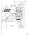
- Figure 1 is schematically showing a power plant section according to this invention, substantially composed by a self-bearing vertical conduit 1 featuring a cylindrical shape and a number of horizontal intake inlets 2 functioning as intake collectors.
- the inlets are anchored to the ground by means of a base 5 and bear inside a cavity that, as better-explained hereby, is suitable to the transport of the air that is taken through the intake conduit and it is driven to the top as a result of the tangible difference in the air density between the intake level and the outlet level, due to the huge dimensions of the conduit 1.
- the power plant could be provided with a conduit of two hundred meter diameter and more than a thousand meters high. The result is a powerful mechanical updraft generating a forced circulation of airflow with a tangible air speed depending on the conduit height and on air temperature T.
- Module 6 represents a battery of wind generators suitable to convert a portion of the kinetic energy and potential energy of the circulating air into electric energy.
- Module 7 represents a battery of burners, for example gas burners suitable to increase the temperature and consequently the air kinetic and potential energy, being the burners strategically positioned on the circumference of duct 3 in order not to stop the main flow of circulating air while efficiently transferring energy to the flow of circulating air.
- Module 8 represents a battery of radiators suitable to release energy to the circulating air in the form of heat collected by a number of solar panels 9 positioned and clung to the external surface of duct 1.
- Ducts 1 and/or 2 are provided with surfaces that are covered inside and/or outside by insulating materials, not represented in the figure, suitable to minimize the losses of heat that would otherwise reduce the energy of the circulating airflow.
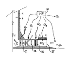
- FIG 2 better shows the main components of the power plant in particular module I, represented above with 6 in figure 1, including the battery of electrical generators 10 each of them powered by connected propeller 11 as better shown in the enlargement.
- Module II previously indicated with 7 in figure 1, including a number of burners 13 positioned parallel to the generators of a tapered surface 13, each connected to a ring fuel distributor 14 feeding these burners; the burners are individually controlled by a process controller (as it will be better explained further on) controlling and regulating the amount of heat released by module II to the circulating air A.
- Module III previously indicated with 8 in figure 1, including a number of radiators 16 positioned inside a frame 15, each hydraulically connected through suitable pipes and pumps, not shown in the figure, to the solar panels 9 transmitting the heat collected from the solar radiations through a thermal-vector fluid circulating and feeding the radiators in connection with suitable connections 17 and 18.
- the pumps are individually controlled by a process controller, as it will be better explained further on, controlling and regulating the amount of heat released by module III to the circulating air A.
- Module IV better represented in the next figures, including a large sun collector which by the solar radiations, thanks to a large surface further increments the temperature of the air flowing from the external of the intake collectors toward the centre according to the path indications given by arrows A, B and C, respectively with a basic energy content of the air secured by the natural updraft and increased by the contribution of each single heating module described above.
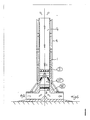
- Figure 3 schematically represents an upper view, partially sectioned in the area of the intake tunnels positioned at the bottom of the power plant where the side walls 20 of the air inlets are shown. It must be noticed that the air inlets are more than two and they are radial converging towards the vertical central air inlet 4 of figure 1.
- the figure also shows in greater detail module IV of figure 2 wherein the surface at the air inlet bottom 1 is closed inside a ring-shaped envelope having a height equivalent to the air inlet and a diameter even exceeding 1000 meters, divided into separate sections, each presenting a large surface exposed to the sun rays penetrating almost completely through the upper covering, purposely built with transparent materials, and almost totally absorbed by the base surface on the ground, purposely realized with materials having a high absorption index so that this absorbed heat is transferred to the air circulating through the space defined by the upper and lower surfaces of the solar collector.
- the collector is a huge solar panel where the cooling fluid is the same circulating air; purposely build in order not to offer minimum pressure losses to the huge airflow crossing through.
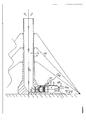
- Figure 4 schematically represents the basic operating process of the power plant. Please note as modules I, II, III and IV previously described and the direction of arrows A, B and C showing how the air flow is taken through the intake horizontal collectors 2, then it flows at the basis of the duct 1 and finally travels vertically towards the top.
- conduit 1 following the air path from A to C, conduit 1 generates a natural updraft forcing air in motion and giving to the air the first quid of kinetic and potential energy Q, then module IV releases a second energy amount Q3 collecting solar energy in the ring-shaped collector, module III releases a third energy amount Q2 from the solar energy collected by the solar panels hung on conduit 1, module II releases the fourth energy amount Q1 from the g as or other fuel combustion, and then module I instead of releasing takes from the air a portion of energy G through the interposed fans.
- the heating means can be of different type, connected in series or in parallel.
- Figures 5 different possible configurations are shown, in particular the most suitable for the developing countries where it is fundamental to maintain very simple plants with a minimum maintenance.
- figure 5a shows module I where the produced energy only depends on the natural whirlpool generated by vertical duct 1
- figure 5 b only shows modules I and II where fuels burners generating heat are the only external energy source that is added to energy Q generated from the natural whirlpool.
- FIG. 5 c shows modules I, II and III where in addition to energy Q there are other contributions available that are coming from the burners and solar panels hung to duct 1.
- Figure 6 shows different embodiment of the power plant of figure 1, wherein modules I, II and II are located vertically inside vertical duct 4.
- Figure 7 shows a simple power plant featuring rather reduced capacities having a unique horizontal tunnel, a typical configuration for the developing countries. It is important to notice that conduit 1 presents a number of wire ropes 22 providing an efficient wind bracing thus allowing building conduit 1 more economically. This figure also shows that the plant can intake (through duct 28 inserting duct 3 of the horizontal collector 2) toxic fumes and discharge them at a high altitude, in order to reduce atmospheric pollution, or alternatively fumes able to provide an additional energy contribution Qr.
- each module is individually suitable to release energy to the air coming from different external sources.
- Each module is connected to a microprocessor 30, suitable to control the individual contribution of each module so that the temperature of the incoming air is constant and consequently also the air speed and the produced electric energy will be constant.
- microprocessor MP compensates by ordering to module II to produce more energy operating different burners simultaneously.
- the microprocessor is of programmable type and suitable to operate different running strategies including the partialisation of the energy released by the modules in case the energy demand decreases.
Landscapes
- Engineering & Computer Science (AREA)
- Chemical & Material Sciences (AREA)
- Combustion & Propulsion (AREA)
- Life Sciences & Earth Sciences (AREA)
- Sustainable Development (AREA)
- Sustainable Energy (AREA)
- Mechanical Engineering (AREA)
- General Engineering & Computer Science (AREA)
- Physics & Mathematics (AREA)
- Thermal Sciences (AREA)
- Power Engineering (AREA)
- Wind Motors (AREA)
Applications Claiming Priority (2)
| Application Number | Priority Date | Filing Date | Title |
|---|---|---|---|
| IT000016A ITPC20040016A1 (it) | 2004-04-19 | 2004-04-19 | Impianto per la produzione di energia dal vento e relativo procedimento. |
| ITPC20040016 | 2004-04-19 |
Publications (2)
| Publication Number | Publication Date |
|---|---|
| EP1589221A2 true EP1589221A2 (fr) | 2005-10-26 |
| EP1589221A3 EP1589221A3 (fr) | 2006-07-19 |
Family
ID=34935154
Family Applications (1)
| Application Number | Title | Priority Date | Filing Date |
|---|---|---|---|
| EP05008150A Withdrawn EP1589221A3 (fr) | 2004-04-19 | 2005-04-14 | Eolienne à effet de cheminée |
Country Status (3)
| Country | Link |
|---|---|
| US (1) | US20060016182A1 (fr) |
| EP (1) | EP1589221A3 (fr) |
| IT (1) | ITPC20040016A1 (fr) |
Cited By (24)
| Publication number | Priority date | Publication date | Assignee | Title |
|---|---|---|---|---|
| FR2910077A1 (fr) * | 2006-12-14 | 2008-06-20 | Jean Stevens | Generateur anemo-solaire |
| WO2008081209A3 (fr) * | 2007-01-03 | 2008-12-04 | Barker Rosemary | Cheminée solaire |
| WO2008142459A3 (fr) * | 2007-05-17 | 2009-05-28 | Emmanuil Dermitzakis | Cheminée en forme de tour solaire composite |
| WO2009013530A3 (fr) * | 2007-07-20 | 2009-11-05 | Oz10 Limited | Ensemble formant structure portable ventilable |
| US7854224B2 (en) | 2007-01-03 | 2010-12-21 | Pitaya Yangpichit | Solar chimney with internal and external solar collectors |
| US7856974B2 (en) | 2007-01-03 | 2010-12-28 | Pitaya Yangpichit | Solar chimney with internal solar collector |
| KR200452175Y1 (ko) | 2008-11-20 | 2011-02-10 | 주식회사 에이브이티 | 하이브리드 발전장치 |
| AT509994B1 (de) * | 2010-08-04 | 2012-01-15 | Penz Alois | Windkraftanlage |
| WO2012079555A1 (fr) * | 2010-12-17 | 2012-06-21 | Lueftl Thomas | Tour solaire à ascendance thermique |
| CN101629551B (zh) * | 2009-08-04 | 2012-08-15 | 张瑞明 | 太阳能热气流发电装置 |
| WO2012061858A3 (fr) * | 2010-11-10 | 2012-08-16 | Alois Penz | Éolienne |
| WO2012145776A1 (fr) * | 2011-04-28 | 2012-11-01 | Alois Penz | Éolienne |
| WO2013091484A1 (fr) * | 2011-12-19 | 2013-06-27 | Yeh Hsin-Chuan | Dispositif de production d'énergie thermique solaire à grande différence de pression et grande différence de température |
| US8534068B2 (en) | 2010-01-15 | 2013-09-17 | Pitaya Yangpichit | Solar chimney with wind turbine |
| WO2013072752A3 (fr) * | 2011-11-18 | 2013-10-17 | Ermilov Sergey Nikolayevich | Procédés et appareils pour déplacer des objets sur la base d'une force de flottaison |
| US8960186B2 (en) | 2007-01-03 | 2015-02-24 | Pitaya Yangpichit | Solar chimney with external solar collector |
| EP2706227A3 (fr) * | 2012-09-07 | 2015-03-11 | IMO Holding GmbH | Centrale hydromotrice pour l'utilisation d'un courant ascendant |
| RU2550580C2 (ru) * | 2013-02-01 | 2015-05-10 | Федеральное государственное бюджетное научное учреждение "Всероссийский научно-исследовательский институт электрификации сельского хозяйства" (ФГБНУ ВИЭСХ) | Электростанция-теплица |
| FR3013804A1 (fr) * | 2013-11-22 | 2015-05-29 | Marius Diver | Cheminee urbaine concue pour produire de l'energie a partir d'une source de chaleur |
| US9062896B2 (en) | 2013-05-16 | 2015-06-23 | Martin Eugene Nix | System to create rotational energy from a wind-chimmey and solar-smelter |
| US9617982B2 (en) | 2011-12-30 | 2017-04-11 | Pitaya Yangpichit | Solar chimney with external vertical axis wind turbine |
| US9970418B2 (en) * | 2010-09-10 | 2018-05-15 | Robert Hunka | Solar energy conversion system |
| RU2689488C1 (ru) * | 2018-11-01 | 2019-05-28 | Александр Алексеевич Соловьев | Биогазовая аэродинамическая установка |
| RU206719U1 (ru) * | 2021-05-24 | 2021-09-23 | Акционерное общество "Русатом Гринвэй" | Биогазовая аэродинамическая установка |
Families Citing this family (14)
| Publication number | Priority date | Publication date | Assignee | Title |
|---|---|---|---|---|
| US7743624B2 (en) * | 2007-01-30 | 2010-06-29 | Millercoors Llc | Beverage dispense font incorporating portable cooling device |
| US20080188174A1 (en) * | 2007-02-01 | 2008-08-07 | Rouzbeh Aminpour | Power system for a building structure |
| US20120055160A1 (en) * | 2009-01-08 | 2012-03-08 | Jianning Peng | Air current generating system and method |
| ES2350991B1 (es) * | 2009-06-03 | 2011-10-14 | Abengoa Solar New Technologies S.A. | Planta de concentracion solar de tecnologia de torre con tiro natural. |
| US20110204648A1 (en) * | 2009-12-14 | 2011-08-25 | Wilson Roger D | Windmill with blades with passageways from hub to tip |
| CN102052255B (zh) * | 2010-12-31 | 2012-03-07 | 北京恒聚化工集团有限责任公司 | 冲击式风力发电装置 |
| EP2674592A1 (fr) * | 2012-06-14 | 2013-12-18 | Siemens Aktiengesellschaft | Procédé de turbine à gaz avec centrale à courant ascendant |
| US9038385B1 (en) | 2013-02-03 | 2015-05-26 | Kyung N. Khim | System for extracting energy from wind and thermal gradients |
| US9097241B1 (en) | 2014-10-02 | 2015-08-04 | Hollick Solar Systems Limited | Transpired solar collector chimney tower |
| US10443570B2 (en) | 2016-02-18 | 2019-10-15 | The Boeing Company | Internal mounted cylindrical turbine for electricity generation using exterior flush and scoop intakes |
| US10947957B1 (en) * | 2018-11-29 | 2021-03-16 | Keith G. Bandy | Apparatus, system and method for utilizing kinetic energy to generate electricity |
| CN114576118A (zh) * | 2022-03-09 | 2022-06-03 | 南京工业大学 | 一种与太阳能光伏光热技术相结合的太阳能烟囱发电系统 |
| CN116123033A (zh) * | 2023-03-13 | 2023-05-16 | 王翠芹 | 一种利用暖棚温差气流进行风力发电的方法 |
| CN120235079B (zh) * | 2025-05-28 | 2025-08-15 | 杭州澳凌制冷设备有限公司 | 一种温差发电模块结构优化设计方法和装置 |
Family Cites Families (11)
| Publication number | Priority date | Publication date | Assignee | Title |
|---|---|---|---|---|
| US3979597A (en) * | 1974-03-05 | 1976-09-07 | Drucker Ernest R | Solar power plant |
| US3936652A (en) * | 1974-03-18 | 1976-02-03 | Levine Steven K | Power system |
| US4106295A (en) * | 1977-03-14 | 1978-08-15 | Wood P John | Air pressure differential energy system |
| US4475342A (en) * | 1979-11-26 | 1984-10-09 | Lucien Y. Bronicki | Method and means for lifting water and generating power therefrom |
| US5284628A (en) * | 1992-09-09 | 1994-02-08 | The United States Of America As Represented By The United States Department Of Energy | Convection towers |
| US5694774A (en) * | 1996-02-29 | 1997-12-09 | Drucker; Ernest R. | Solar energy powerplant |
| DE19811310A1 (de) * | 1998-03-16 | 1999-09-23 | Heilmeier Guenter | Kaminähnliche Vorrichtung |
| US5983634A (en) * | 1998-03-18 | 1999-11-16 | Drucker; Ernest R. | Solar energy powerplant with mobile reflector walls |
| IL153247A0 (en) * | 2000-06-14 | 2003-07-06 | Ernest R Drucker | Solar chimney wind turbine |
| DE10193399D2 (de) * | 2000-08-16 | 2003-07-03 | Herbert Jenner | Windkraftanlage mit Kamineffekt |
| DE10102675A1 (de) * | 2001-01-17 | 2002-07-18 | Manfred Rose | Kombinationskraftwerk |
-
2004
- 2004-04-19 IT IT000016A patent/ITPC20040016A1/it unknown
-
2005
- 2005-04-14 EP EP05008150A patent/EP1589221A3/fr not_active Withdrawn
- 2005-04-18 US US11/111,475 patent/US20060016182A1/en not_active Abandoned
Cited By (27)
| Publication number | Priority date | Publication date | Assignee | Title |
|---|---|---|---|---|
| FR2910077A1 (fr) * | 2006-12-14 | 2008-06-20 | Jean Stevens | Generateur anemo-solaire |
| US7854224B2 (en) | 2007-01-03 | 2010-12-21 | Pitaya Yangpichit | Solar chimney with internal and external solar collectors |
| WO2008081209A3 (fr) * | 2007-01-03 | 2008-12-04 | Barker Rosemary | Cheminée solaire |
| US8960186B2 (en) | 2007-01-03 | 2015-02-24 | Pitaya Yangpichit | Solar chimney with external solar collector |
| US7856974B2 (en) | 2007-01-03 | 2010-12-28 | Pitaya Yangpichit | Solar chimney with internal solar collector |
| WO2008142459A3 (fr) * | 2007-05-17 | 2009-05-28 | Emmanuil Dermitzakis | Cheminée en forme de tour solaire composite |
| WO2009013530A3 (fr) * | 2007-07-20 | 2009-11-05 | Oz10 Limited | Ensemble formant structure portable ventilable |
| KR200452175Y1 (ko) | 2008-11-20 | 2011-02-10 | 주식회사 에이브이티 | 하이브리드 발전장치 |
| CN101629551B (zh) * | 2009-08-04 | 2012-08-15 | 张瑞明 | 太阳能热气流发电装置 |
| US9903349B2 (en) | 2010-01-15 | 2018-02-27 | Pitaya Yangpichit | Solar chimney with wind turbine |
| US8534068B2 (en) | 2010-01-15 | 2013-09-17 | Pitaya Yangpichit | Solar chimney with wind turbine |
| AT509994A4 (de) * | 2010-08-04 | 2012-01-15 | Penz Alois | Windkraftanlage |
| AT509994B1 (de) * | 2010-08-04 | 2012-01-15 | Penz Alois | Windkraftanlage |
| US9970418B2 (en) * | 2010-09-10 | 2018-05-15 | Robert Hunka | Solar energy conversion system |
| WO2012061858A3 (fr) * | 2010-11-10 | 2012-08-16 | Alois Penz | Éolienne |
| WO2012079555A1 (fr) * | 2010-12-17 | 2012-06-21 | Lueftl Thomas | Tour solaire à ascendance thermique |
| WO2012145776A1 (fr) * | 2011-04-28 | 2012-11-01 | Alois Penz | Éolienne |
| US9039334B2 (en) | 2011-11-18 | 2015-05-26 | Sergey Nikolayevich Ermilov | Methods and apparatuses for moving objects based on a buoyancy force |
| WO2013072752A3 (fr) * | 2011-11-18 | 2013-10-17 | Ermilov Sergey Nikolayevich | Procédés et appareils pour déplacer des objets sur la base d'une force de flottaison |
| WO2013091484A1 (fr) * | 2011-12-19 | 2013-06-27 | Yeh Hsin-Chuan | Dispositif de production d'énergie thermique solaire à grande différence de pression et grande différence de température |
| US9617982B2 (en) | 2011-12-30 | 2017-04-11 | Pitaya Yangpichit | Solar chimney with external vertical axis wind turbine |
| EP2706227A3 (fr) * | 2012-09-07 | 2015-03-11 | IMO Holding GmbH | Centrale hydromotrice pour l'utilisation d'un courant ascendant |
| RU2550580C2 (ru) * | 2013-02-01 | 2015-05-10 | Федеральное государственное бюджетное научное учреждение "Всероссийский научно-исследовательский институт электрификации сельского хозяйства" (ФГБНУ ВИЭСХ) | Электростанция-теплица |
| US9062896B2 (en) | 2013-05-16 | 2015-06-23 | Martin Eugene Nix | System to create rotational energy from a wind-chimmey and solar-smelter |
| FR3013804A1 (fr) * | 2013-11-22 | 2015-05-29 | Marius Diver | Cheminee urbaine concue pour produire de l'energie a partir d'une source de chaleur |
| RU2689488C1 (ru) * | 2018-11-01 | 2019-05-28 | Александр Алексеевич Соловьев | Биогазовая аэродинамическая установка |
| RU206719U1 (ru) * | 2021-05-24 | 2021-09-23 | Акционерное общество "Русатом Гринвэй" | Биогазовая аэродинамическая установка |
Also Published As
| Publication number | Publication date |
|---|---|
| US20060016182A1 (en) | 2006-01-26 |
| ITPC20040016A1 (it) | 2004-07-19 |
| EP1589221A3 (fr) | 2006-07-19 |
Similar Documents
| Publication | Publication Date | Title |
|---|---|---|
| EP1589221A2 (fr) | Eolienne à effet de cheminée | |
| US7552589B2 (en) | Structure and methods using multi-systems for electricity generation and water desalination | |
| AU2001267224B2 (en) | Solar chimney wind turbine | |
| US9574551B2 (en) | Power tower—system and method of using air flow generated by geothermal generated heat to drive turbines generators for the generation of electricity | |
| US5983634A (en) | Solar energy powerplant with mobile reflector walls | |
| US5694774A (en) | Solar energy powerplant | |
| US8487463B2 (en) | Enhanced multi-mode power generation system | |
| AU2001267224A1 (en) | Solar chimney wind turbine | |
| CN101535637A (zh) | 供热系统,风轮机或风电场,利用一个或多个风轮机部件的多余热量的方法及其使用 | |
| JP2014505195A (ja) | 自然エネルギー蓄積発電方法とその発電システム | |
| US7154190B2 (en) | All-weather energy and water production via steam-enhanced vortex tower | |
| US10961987B2 (en) | Solar collector and turbine arrangement | |
| US7340898B2 (en) | Solar-thermal powered generator | |
| Ngala et al. | Review of solar chimney power technology and its potentials in semi-arid region of Nigeria | |
| CN102410141A (zh) | 风光兼备辅助热力成机制太阳塔式电力输出优化集成系统 | |
| CN202300853U (zh) | 风光兼备辅助热力成机制太阳塔式电力输出优化集成系统 | |
| WO2015017879A1 (fr) | Ensemble fenêtre à génération d'énergie | |
| CN105275746A (zh) | 自造风风力发电系统 | |
| CN202381259U (zh) | 发电塔涡轮涡扇运转结构 | |
| CN102322410B (zh) | 利用太阳能形成热气流发电的方法 | |
| US10859066B2 (en) | Sub-terranean updraft tower (STUT) power generator | |
| RU2244849C2 (ru) | Ветротепловая энергетическая установка | |
| RU2373430C2 (ru) | Солнечная теплоэлектростанция с применением вихревых камер | |
| AU2017101410A4 (en) | Recuperation of waste heat to co-generate electricity in solar-wind farms | |
| KR20070029713A (ko) | 발전 및 담수화를 위한 복합 장치를 이용하는 구조물 및방법 |
Legal Events
| Date | Code | Title | Description |
|---|---|---|---|
| PUAI | Public reference made under article 153(3) epc to a published international application that has entered the european phase |
Free format text: ORIGINAL CODE: 0009012 |
|
| AK | Designated contracting states |
Kind code of ref document: A2 Designated state(s): AT BE BG CH CY CZ DE DK EE ES FI FR GB GR HU IE IS IT LI LT LU MC NL PL PT RO SE SI SK TR |
|
| AX | Request for extension of the european patent |
Extension state: AL BA HR LV MK YU |
|
| PUAL | Search report despatched |
Free format text: ORIGINAL CODE: 0009013 |
|
| AK | Designated contracting states |
Kind code of ref document: A3 Designated state(s): AT BE BG CH CY CZ DE DK EE ES FI FR GB GR HU IE IS IT LI LT LU MC NL PL PT RO SE SI SK TR |
|
| AX | Request for extension of the european patent |
Extension state: AL BA HR LV MK YU |
|
| RIC1 | Information provided on ipc code assigned before grant |
Ipc: F03D 1/04 20060101ALI20060609BHEP Ipc: F03G 6/04 20060101AFI20060609BHEP |
|
| AKX | Designation fees paid | ||
| 17P | Request for examination filed |
Effective date: 20070123 |
|
| RBV | Designated contracting states (corrected) |
Designated state(s): AT BE BG CH CY CZ DE DK EE ES FI FR GB GR HU IE IS IT LI LT LU MC NL PL PT RO SE SI SK TR |
|
| REG | Reference to a national code |
Ref country code: DE Ref legal event code: 8566 |
|
| STAA | Information on the status of an ep patent application or granted ep patent |
Free format text: STATUS: THE APPLICATION IS DEEMED TO BE WITHDRAWN |
|
| 18D | Application deemed to be withdrawn |
Effective date: 20081101 |