EP1589204A2 - Wärmetauscher für eine Gasturbine - Google Patents
Wärmetauscher für eine Gasturbine Download PDFInfo
- Publication number
- EP1589204A2 EP1589204A2 EP05252429A EP05252429A EP1589204A2 EP 1589204 A2 EP1589204 A2 EP 1589204A2 EP 05252429 A EP05252429 A EP 05252429A EP 05252429 A EP05252429 A EP 05252429A EP 1589204 A2 EP1589204 A2 EP 1589204A2
- Authority
- EP
- European Patent Office
- Prior art keywords
- heat exchanger
- gas turbine
- coupled
- compressor
- exchanger assembly
- Prior art date
- Legal status (The legal status is an assumption and is not a legal conclusion. Google has not performed a legal analysis and makes no representation as to the accuracy of the status listed.)
- Granted
Links
Images


Classifications
-
- F—MECHANICAL ENGINEERING; LIGHTING; HEATING; WEAPONS; BLASTING
- F02—COMBUSTION ENGINES; HOT-GAS OR COMBUSTION-PRODUCT ENGINE PLANTS
- F02C—GAS-TURBINE PLANTS; AIR INTAKES FOR JET-PROPULSION PLANTS; CONTROLLING FUEL SUPPLY IN AIR-BREATHING JET-PROPULSION PLANTS
- F02C7/00—Features, components parts, details or accessories, not provided for in, or of interest apart form groups F02C1/00 - F02C6/00; Air intakes for jet-propulsion plants
- F02C7/08—Heating air supply before combustion, e.g. by exhaust gases
- F02C7/10—Heating air supply before combustion, e.g. by exhaust gases by means of regenerative heat-exchangers
-
- F—MECHANICAL ENGINEERING; LIGHTING; HEATING; WEAPONS; BLASTING
- F28—HEAT EXCHANGE IN GENERAL
- F28D—HEAT-EXCHANGE APPARATUS, NOT PROVIDED FOR IN ANOTHER SUBCLASS, IN WHICH THE HEAT-EXCHANGE MEDIA DO NOT COME INTO DIRECT CONTACT
- F28D7/00—Heat-exchange apparatus having stationary tubular conduit assemblies for both heat-exchange media, the media being in contact with different sides of a conduit wall
- F28D7/0058—Heat-exchange apparatus having stationary tubular conduit assemblies for both heat-exchange media, the media being in contact with different sides of a conduit wall the conduits for only one medium being tubes having different orientations to each other or crossing the conduit for the other heat exchange medium
-
- F—MECHANICAL ENGINEERING; LIGHTING; HEATING; WEAPONS; BLASTING
- F28—HEAT EXCHANGE IN GENERAL
- F28D—HEAT-EXCHANGE APPARATUS, NOT PROVIDED FOR IN ANOTHER SUBCLASS, IN WHICH THE HEAT-EXCHANGE MEDIA DO NOT COME INTO DIRECT CONTACT
- F28D21/00—Heat-exchange apparatus not covered by any of the groups F28D1/00 - F28D20/00
- F28D21/0001—Recuperative heat exchangers
- F28D21/0003—Recuperative heat exchangers the heat being recuperated from exhaust gases
Definitions
- This invention relates generally to gas turbine engines, and more particularly to heat exchangers used with gas turbine engines.
- At least one known gas turbine engine uses a heat exchanger, generally referred to as a recuperator, to facilitate reducing specific fuel consumption. More specifically, pressurized air from the compressor section of the gas turbine engine is channeled from the gas turbine engine, and through the heat exchanger, such that the hot exhaust gases of the engine raise the operating temperature of the pressurized air prior to it being supplied into the combustor.
- known heat exchanger assemblies are positioned between the gas turbine engine exhaust gas box and the exhaust stack. At least some known heat exchanger assemblies include a pair of heat exchangers coupled in a parallel spaced relationship such that a space known as a bypass duct is defined therebetween. The bypass duct is closable by a butterfly valve.
- known heat exchangers are typically physically large and rectangular-shaped, such heat exchangers are mounted externally to the gas turbine engine. Accordingly, the compressor discharge air and the engine exhaust gas is routed to and from the heat exchangers through a ducting which couples the heat exchangers to the gas turbine engine.
- known heat exchanger assemblies occupy a relatively large volume which is often larger than a volume occupied by the gas turbine engine itself. The resulting large and irregular heat exchanger assembly, coupled with the added weight and cost of the heat exchanger and ducting, generally makes regenerative engine systems unfeasible for aircraft applications.
- recuperated engines generally achieve a better low power specific fuel consumption than other known gas turbine engines
- gas-side total pressure losses of the hot exhaust gas stream may be relatively high through the exhaust system heat exchanger.
- the increased gas-side pressure losses caused by the heat exchanger assembly may result in an increased specific fuel consumption.
- the size of the heat exchanger is generally desired to be as small as possible, less space is available for a bypass system, which may result in high exhaust total pressure losses during high-power engine operating conditions.
- a method for assembling a gas turbine engine includes providing a heat exchanger assembly that includes at least one heat exchanger, and coupling the heat exchanger assembly to the gas turbine engine such that the heat exchanger is positioned substantially concentrically with respect to a gas turbine engine axis of rotation, and such that the heat exchanger is configured to channel compressor discharge air from the compressor discharge air to the combustor.
- a heat exchanger assembly for a gas turbine engine is provided.
- the heat exchanger is coupled in flow communication to a compressor.
- the heat exchanger is configured to channel compressor discharge air to a combustor.
- the heat exchanger assembly is coupled to the gas turbine engine such that the heat exchanger is substantially concentrically aligned with respect to an axis of rotation of the gas turbine engine.
- a gas turbine engine in a further aspect, includes a compressor, a combustor downstream from the compressor, a turbine coupled in flow communication with the combustor, and a heat exchanger assembly.
- the heat exchanger is configured to channel compressor discharge air to a combustor.
- the heat exchanger assembly is coupled to the gas turbine engine such that the heat exchanger is substantially concentrically aligned with respect to an axis of rotation of the gas turbine engine.
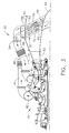
- FIG 1 is a perspective view of an exemplary gas turbine engine 10 including a heat exchanger assembly 50.
- Figure 2 is a block diagram of gas turbine engine 10 (shown in Figure 1).
- Gas turbine engine 10 includes, in serial flow relationship, a low pressure compressor or booster 14, a high pressure compressor 16, a combustor 18, a high pressure turbine 20, a low pressure, or intermediate turbine 22, and a power turbine or free turbine 24.
- Low pressure compressor or booster 14 has an inlet 26 and an outlet 28, and high pressure compressor 16 includes an inlet 30 and an outlet 32.
- Combustor 18 has an inlet 34 that is substantially coincident with high pressure compressor outlet 32, and an outlet 36.
- combustor 18 is an annular combustor.
- combustor 18 is a dry low emissions (DLE) combustor.
- DLE dry low emissions
- High pressure turbine 20 is coupled to high pressure compressor 16 with a first rotor shaft 40, and low pressure turbine 22 is coupled to low pressure compressor 14 with a second rotor shaft 42.
- Rotor shafts 40 and 42 are each substantially coaxially aligned with respect to a longitudinal centerline axis of rotation 43 of engine 10.
- Engine 10 may be used to drive a load (not shown) which may be coupled to a power turbine shaft 44. Alternatively, the load may be coupled to a forward extension (not shown) of rotor shaft 42.
- ambient air drawn into low pressure compressor inlet 26 is compressed and channeled downstream to high pressure compressor 16.
- High pressure compressor 16 further compresses the air and delivers high pressure air to combustor 18 where it is mixed with fuel, and the mixture is ignited to generate high temperature combustion gases.
- the combustion gases are channeled from combustor 18 to drive turbines 20, 22, and 24.
- the power output of engine 10 is at least partially related to operating temperatures of the gas flow at various locations along the gas flow path. More specifically, in the exemplary embodiment, an operating temperature of the gas flow at high-pressure compressor outlet 32, and an operating temperature of the gas flow at combustor outlet 36 are closely monitored during the operation of engine 10. Increasing an operating temperature of the gas flow entering combustor 18 facilitates increasing the specific fuel consumption of engine 10.
- FIG 3 is a side view of heat exchanger assembly 50 shown in Figure 1.
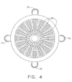
- Figure 4 is an end view of heat exchanger assembly 50.
- heat exchanger assembly 50 is removably coupled to a gas turbine rear frame 52 of gas turbine engine 10 and includes an outer casing 54, an inlet manifold 56, an outlet manifold 58, and a heat exchanger 60 coupled to outer casing 54.
- inlet manifold 56 and outlet manifold 58 are formed unitarily together.
- inlet manifold 56 and outlet manifold 58 are fabricated as separate components and are coupled together prior to being coupled to outer casing 54.
- inlet manifold 56 and outlet manifold 58 are formed unitarily with outer casing 54.
- Heat exchanger 60 includes a plurality of heat exchangers elements 62 that extend substantially circumferentially around an engine inside diameter between an outer periphery of a fixed plug nozzle 64 and an inner periphery of outer casing 54.
- Each heat exchanger element 62 includes an inlet side 70 that is in flow communication with inlet manifold 56, an outlet side 72 that is in flow communication with outlet manifold 58 and inlet side 70.
- Heat exchanger assembly 50 also includes a compressor discharge pipe 74, i.e., a cold pipe, that is in flow communication with inlet manifold 56, and a combustor inlet pipe 76, i.e., a hot pipe, that is in flow communication with outlet manifold 58.
- heat exchanger 60 is an annular heat exchanger that is positioned within outer casing 54. In another embodiment, heat exchanger 60 is at least one of a radial heat exchanger and/or a crossflow heat exchanger that is positioned within outer casing 54.
- heat exchanger assembly 50 is coupled to turbine rear frame 52 such that heat exchanger 60 is aligned substantially concentrically with respect to gas turbine engine axis of rotation 43.
- a sealing apparatus (not shown) is positioned aft of the last stage of compressor 16 to facilitate channeling compressed air to each heat exchanger element 62 via inlet manifold 56. More specifically, in the exemplary embodiment, a first end 80 of compressor discharge pipe 74 is coupled to inlet manifold 56, and a second end 82 of compressor discharge pipe 74 is coupled to compressor 16, such that compressor 16 is coupled in flow communication with inlet manifold 56.
- a first end 84 of combustor inlet pipe 76 is coupled to outlet manifold 58, and a second end 86 of combustor inlet pipe 76 is coupled to combustor 18, such that combustor 18 is coupled in flow communication with outlet manifold 58.
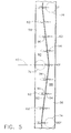
- Figure 5 is a plan view of inlet manifold 56 and outlet manifold 58.
- inlet manifold 56 and outlet manifold 58 extend 360 degrees around an outer surface of outer casing 54 although only ninety degrees of inlet manifold 56 and outlet manifold 58 are shown.
- Inlet manifold 56 includes a cross-sectional area 88 and outlet manifold 58 includes a cross-sectional area 90 that is inversely proportional to cross-sectional area 88.
- inlet manifold 56 and outlet manifold 58 are separated by a divider 92 such that an inlet side 94 of each heat exchanger element 62 is in flow communication with inlet manifold 56 and an outlet side 96 of each heat exchanger element 62 is in flow communication with outlet manifold 58.
- heat exchanger elements 62 are arranged such that a central axis 98 of each heat exchanger element 62 is substantially aligned with divider 92 and such that plurality of heat exchanger elements 62 form an approximately sinusoidal arrangement around an inner periphery of outer casing 54 with respect to axis of rotation 43.
- compressor discharge air from compressor 16 is channeled via compressor discharge pipe 74 to inlet manifold 56.
- the compressor discharge air is then channeled through inlet side 70 of each heat exchanger element 62 and is placed in heat exchange with the hot exhaust gases of gas turbine engine 10.
- each heat exchanger element 62 includes a plurality of heating fins 99, and the hot exhaust gases are channeled over heating fins 99 to facilitate transferring heat energy from the hot exhaust gases to the compressor discharge air.
- the heated compressor discharge air is then channeled through outlet side 72 of each heat exchanger element 62, through outlet manifold 58, and returned to engine 10, via combustor inlet pipe 76, whereupon the heated compressed air is channeled to combustor section 18.
- the heat exchanger assembly includes an annular heat exchanger that is coupled against the turbine rear frame.
- the annular heat exchanger is relatively small compared to known heat exchangers, thus enabling the heat exchanger to be coupled within the gas turbine engine outer casing aft of the gas turbine engine wherein known heat exchangers can not be used because of restricted space limitations.
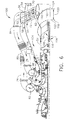
- FIG 6 is a side view of an alternative embodiment of a heat exchanger assembly 100 that can be used with gas turbine 10 (shown in Figure 1).
- Heat exchanger assembly 100 is substantially similar to heat exchanger assembly 50, (shown in Figures 3 and 4) and components of heat exchanger assembly 100 that are identical to components of heat exchanger assembly 50 are identified in Figure 5 using the same reference numerals used in Figures 3 and 4.
- heat exchanger assembly 100 is removably coupled to a gas turbine rear frame 52 of gas turbine engine 10 and includes an outer casing 54, an inlet manifold 56, an outlet manifold 58, and a heat exchanger 60 coupled to outer casing 54.
- inlet manifold 56 and outlet manifold 58 are formed unitarily together.
- inlet manifold 56 and outlet manifold 58 are fabricated as separate components and are coupled together prior to being coupled to outer casing 54.
- inlet manifold 56 and outlet manifold 58 are formed unitarily with outer casing 54.
- Heat exchanger 60 includes a plurality of heat exchanger elements 62 that extend substantially circumferentially around an engine inside diameter between an outer periphery of a variable plug nozzle 102 and an inner periphery of outer casing 54.
- Each heat exchanger element 62 includes an inlet side 70 that is in flow communication with inlet manifold 56, and an outlet side 72 that is in flow communication with outlet manifold 58.
- Heat exchanger assembly 100 also includes a compressor discharge pipe 74, i.e., a cold pipe that is in flow communication with inlet manifold 56, and a combustor inlet pipe 76, i.e., a hot pipe that is in flow communication with outlet manifold 58.
- heat exchanger 60 is an annular heat exchanger that is positioned within outer casing 54. In another embodiment, heat exchanger 60 is at least one of a radial heat exchanger and/or a crossflow heat exchanger that is positioned within outer casing 54.
- Heat exchanger assembly 100 also includes a variable plug nozzle drive assembly 104 that includes an electric motor drive assembly 106 coupled to a drive apparatus 108.
- Variable plug nozzle 102 includes a nozzle 110 and a driving portion 112 coupled to nozzle 110.
- drive apparatus 108 is a worm gear and driving portion 112 is slidably coupled to drive apparatus 108 such that when motor assembly 106 is energized, drive apparatus 108 is rotated in either a first direction 114 or a second direction 116. Rotating drive apparatus 108 in either first direction 114 or second direction 116 facilitates transitioning nozzle 102 in either a first axial direction 118 or a second axial direction 120 respectively.
- heat exchanger assembly 100 During installation of heat exchanger assembly 100, heat exchanger assembly 100, including variable plug nozzle drive assembly 104, is coupled to turbine rear frame 52 such that heat exchanger 60 is aligned substantially concentrically with respect to gas turbine engine axis of rotation 43.
- a sealing apparatus (not shown) is positioned aft of the last stage of compressor 16 to facilitate channeling compressed air to each heat exchanger element 62 via inlet manifold 56. More specifically, in the exemplary embodiment, a first end 80 of compressor discharge pipe 74 is coupled to inlet manifold 56, and a second end 82 of compressor discharge pipe 74 is coupled to compressor 16, such that compressor 16 is coupled in flow communication with inlet manifold 56.
- a first end 84 of combustor inlet pipe 76 is coupled to outlet manifold 58, and a second end 86 of combustor inlet pipe 76 is coupled to combustor 18, such that combustor 18 is coupled in flow communication with outlet manifold 58.
- compressor discharge air from compressor 16 is channeled via compressor discharge pipe 74 to inlet manifold 56.
- the compressor discharge air is then channeled through an inlet side 70 of each heat exchanger element 62 and is placed in heat exchange with the hot exhaust gases of gas turbine engine 10.
- each heat exchanger element 62 includes a plurality of heating fins 99, and the hot exhaust gases are channeled over heating fins 99 to facilitate transferring heat energy from the hot exhaust gases to the compressor discharge air.
- the heated compressor discharge air is then channeled through outlet side 72 of each heat exchanger element 62, through outlet manifold 58, and returned to engine 10, via combustor inlet pipe 76, whereupon the heated compressed air is channeled to combustor section 18.
- the heated compressor discharge air is then channeled through an outlet side 72 of each heat exchanger element 62, through outlet manifold 58 and returned to engine 10, via combustor inlet pipe 76, whereupon the heated compressed air is channeled to combustor section 18.
- variable nozzle assembly 102 is transitioned from a first position 122 to a second position 124 by energizing motor drive assembly 104.
- Energizing motor drive system 104 i.e., motor 106, rotates drive apparatus 108 in a second direction 116.
- driving portion 112 is coupled to both driving mechanism 108 and nozzle 110, rotating driving mechanism 108 transitions nozzle 110 from a first direction 118 to a second direction 120 thus channeling a substantial portion of turbine 24 discharge air through heat exchanger 60 to facilitate heating the compressor discharge air channeled from compressor 16 through heat exchanger 60 and back to combustor 18. Heating a substantial portion of the compressor discharge air facilitates increasing the specific fuel consumption of gas turbine engine 10.
- energizing motor drive assembly 104 causes variable nozzle assembly 102 to transition from a second position 124 to a first position 122.
- Energizing motor drive system 104 i.e. motor 106, rotates drive apparatus 108 in a first direction 114. Since, driving portion 112 is coupled to both driving mechanism 108 and nozzle 110, rotating driving mechanism 108 causes nozzle 110 to transition from second direction 120 to first direction 118 thus channeling a substantial portion of turbine 24 discharge air around heat exchanger 60 and through the engine exhaust when heated combustor air is not desired.
- the heat exchanger assembly provides a cost-effective and reliable means to facilitate increasing the specific fuel consumption of a gas turbine engine. More specifically, the heat exchanger assembly includes an annular heat exchanger that is coupled against the turbine rear frame. The annular heat exchanger is relatively small compared to known heat exchangers, thus enabling the heat exchanger to be coupled within the gas turbine engine outer casing aft of the gas turbine engine.
- the above-described heat exchanger can thus be used with a plurality of known gas turbine engines in a variety of different applications. For example, the above-described heat exchanger can be coupled to gas turbine engines used with airplanes, helicopters, and various marine applications. Moreover, the above-described heat exchanger can be used in a plurality of applications wherein known heat exchangers can not be used because of restricted space limitations.
- the above-described heat exchanger assemblies can be pre-assembled prior to installing the heat exchanger assembly on the gas turbine engine. More specifically, the heat exchanger assembly can be provided as a kit that may be coupled to an existing engine.
- the main components i.e., the heat exchanger, the inlet and outlet manifolds, the nozzle, and the outer casing are pre-assembled.
- the main components are then coupled to the turbine rear frame, the compressor outlet pipe is coupled to the inlet manifold and the combustor inlet pipe is coupled to the outlet manifold to complete the installation on any known gas turbine engine.
- heat exchanger assembly components illustrated are not limited to the specific embodiments described herein, but rather, components of each heat exchanger assembly may be utilized independently and separately from other components described herein.
- the annular heat exchanger described above may also be used in combination with other engine combustion systems.
Landscapes
- Engineering & Computer Science (AREA)
- Chemical & Material Sciences (AREA)
- Combustion & Propulsion (AREA)
- Mechanical Engineering (AREA)
- General Engineering & Computer Science (AREA)
- Physics & Mathematics (AREA)
- Thermal Sciences (AREA)
- Heat-Exchange Devices With Radiators And Conduit Assemblies (AREA)
- Structures Of Non-Positive Displacement Pumps (AREA)
Applications Claiming Priority (2)
| Application Number | Priority Date | Filing Date | Title |
|---|---|---|---|
| US10/828,663 US7254937B2 (en) | 2004-04-21 | 2004-04-21 | Gas turbine heat exchanger assembly and method for fabricating same |
| US828663 | 2004-04-21 |
Publications (3)
| Publication Number | Publication Date |
|---|---|
| EP1589204A2 true EP1589204A2 (de) | 2005-10-26 |
| EP1589204A3 EP1589204A3 (de) | 2013-01-09 |
| EP1589204B1 EP1589204B1 (de) | 2017-01-04 |
Family
ID=34940904
Family Applications (1)
| Application Number | Title | Priority Date | Filing Date |
|---|---|---|---|
| EP05252429.5A Expired - Lifetime EP1589204B1 (de) | 2004-04-21 | 2005-04-19 | Wärmetauscher für eine Gasturbine |
Country Status (2)
| Country | Link |
|---|---|
| US (1) | US7254937B2 (de) |
| EP (1) | EP1589204B1 (de) |
Cited By (10)
| Publication number | Priority date | Publication date | Assignee | Title |
|---|---|---|---|---|
| WO2007128280A1 (de) * | 2006-05-09 | 2007-11-15 | Mtu Aero Engines Gmbh | Gasturbinentriebwerk |
| FR2962487A1 (fr) * | 2010-07-06 | 2012-01-13 | Turbomeca | Architecture d'echange de chaleur integree a l'echappement d'une turbomachine |
| DE102011008773A1 (de) | 2011-01-18 | 2012-07-19 | Mtu Aero Engines Gmbh | Wärmetauscher und Strahltriebwerk mit solchem |
| EP2492472A1 (de) * | 2011-02-28 | 2012-08-29 | Pratt & Whitney Canada Corp. | Diffusionsrekuperator für einen Gasturbinenmotor |
| WO2012071166A3 (en) * | 2010-11-22 | 2013-06-20 | General Electric Company | Integrated variable geometry flow restrictor and heat exchanger |
| US9394828B2 (en) | 2011-02-28 | 2016-07-19 | Pratt & Whitney Canada Corp. | Gas turbine engine recuperator with floating connection |
| US9766019B2 (en) | 2011-02-28 | 2017-09-19 | Pratt & Whitney Canada Corp. | Swirl reducing gas turbine engine recuperator |
| FR3135111A1 (fr) * | 2022-04-29 | 2023-11-03 | Safran Helicopter Engines | Turbomoteur comprenant un echangeur de chaleur |
| FR3140906A1 (fr) * | 2022-10-18 | 2024-04-19 | Safran Helicopter Engines | Turbomachine a cycle recupere equipee d’un echangeur de chaleur |
| FR3155030A1 (fr) * | 2023-11-03 | 2025-05-09 | Safran Aircraft Engines | Turbomachine pour aeronef |
Families Citing this family (25)
| Publication number | Priority date | Publication date | Assignee | Title |
|---|---|---|---|---|
| US7383686B2 (en) * | 2004-12-13 | 2008-06-10 | Honeywell International Inc. | Secondary flow, high pressure turbine module cooling air system for recuperated gas turbine engines |
| US8516791B2 (en) * | 2007-07-30 | 2013-08-27 | General Electric Company | Methods and apparatus for mixing fluid in turbine engines |
| US8438835B2 (en) * | 2007-07-30 | 2013-05-14 | General Electric Company | Methods and apparatus for mixing fluid in turbine engines |
| US8181443B2 (en) * | 2008-12-10 | 2012-05-22 | Pratt & Whitney Canada Corp. | Heat exchanger to cool turbine air cooling flow |
| US8499544B2 (en) * | 2009-11-17 | 2013-08-06 | General Electric Company | Turbogenerator with cooling system |
| WO2013147953A1 (en) * | 2011-12-30 | 2013-10-03 | Rolls-Royce North American Technologies Inc. | Aircraft propulsion gas turbine engine with heat exchange |
| US9541008B2 (en) * | 2012-02-06 | 2017-01-10 | General Electric Company | Method and apparatus to control part-load performance of a turbine |
| FR3016654B1 (fr) * | 2014-01-21 | 2019-06-07 | Safran Aircraft Engines | Turbomachine a prelevement de flux d'air comprime |
| EP2927596A1 (de) * | 2014-03-31 | 2015-10-07 | Siemens Aktiengesellschaft | Silobrennkammer für eine Gasturbine |
| DE102014214038B4 (de) * | 2014-07-18 | 2016-10-13 | MTU Aero Engines AG | Gasturbine |
| CA3006361A1 (en) * | 2015-12-04 | 2017-07-06 | Jetoptera, Inc. | Micro-turbine gas generator and propulsive system |
| FR3044705B1 (fr) * | 2015-12-07 | 2019-11-01 | Safran Aircraft Engines | Systeme de decharge d'un flux de compresseur d'une turbomachine |
| GB2551181A (en) * | 2016-06-09 | 2017-12-13 | Hieta Tech Limited | Radial flow turbine heat engine |
| GB201618016D0 (en) * | 2016-10-25 | 2016-12-07 | Jiang Kyle | Gas turbine engine |
| US10830141B2 (en) * | 2017-12-15 | 2020-11-10 | General Electric Company | Recuperator for gas turbine engine |
| US10941706B2 (en) | 2018-02-13 | 2021-03-09 | General Electric Company | Closed cycle heat engine for a gas turbine engine |
| US11143104B2 (en) | 2018-02-20 | 2021-10-12 | General Electric Company | Thermal management system |
| FR3088962A1 (fr) | 2018-11-27 | 2020-05-29 | Temisth Sas | Échangeur thermique et turbomachine associée |
| US11391211B2 (en) * | 2018-11-28 | 2022-07-19 | General Electric Company | Waste heat recovery system |
| US11015534B2 (en) | 2018-11-28 | 2021-05-25 | General Electric Company | Thermal management system |
| US11492924B1 (en) * | 2021-04-26 | 2022-11-08 | General Electric Company Polska sp. z o.o | Embedded electric machine cooling |
| NO20210915A1 (no) * | 2021-07-16 | 2022-08-22 | Åge Jørgen Skomsvold | Anordning for å frembringe høyere trykk og temperatur av en gass |
| US11946415B2 (en) * | 2021-09-09 | 2024-04-02 | General Electric Company | Waste heat recovery system |
| US12037943B2 (en) * | 2022-10-07 | 2024-07-16 | General Electric Company | Waste heat recovery system |
| FR3159632A1 (fr) * | 2024-02-26 | 2025-08-29 | Safran Aircraft Engines | Sous-ensemble de turbomachine d’aéronef à architecture améliorée et turbomachine d’aéronef comportant un tel sous-ensemble |
Family Cites Families (11)
| Publication number | Priority date | Publication date | Assignee | Title |
|---|---|---|---|---|
| GB659151A (en) * | 1948-06-02 | 1951-10-17 | Westinghouse Electric Int Co | Improvements in or relating to gas turbine power plants |
| US2925714A (en) * | 1954-10-11 | 1960-02-23 | Thompson Ramo Wooldridge Inc | Diffuser-regenerator gas turbine engine |
| US2969642A (en) * | 1957-12-04 | 1961-01-31 | United Aircraft Corp | Radiator matrix design |
| US3222864A (en) * | 1962-12-31 | 1965-12-14 | Garrett Corp | Gas turbine engine fixed boundary recuperator |
| US3201938A (en) * | 1963-06-27 | 1965-08-24 | Gen Electric | Recuperative arrangement for gas turbine engines |
| US3386243A (en) * | 1966-09-12 | 1968-06-04 | Gen Motors Corp | Bypass valve for recuperative gas turbines |
| US3735588A (en) * | 1971-07-21 | 1973-05-29 | Curtiss Wright Corp | Heat exchanger leakage baffle and positioning means |
| US3701381A (en) * | 1971-07-21 | 1972-10-31 | Curtiss Wright Corp | Heat exchanger supporting means |
| US4050242A (en) | 1975-12-01 | 1977-09-27 | General Electric Company | Multiple bypass-duct turbofan with annular flow plug nozzle and method of operating same |
| US5396760A (en) | 1993-11-03 | 1995-03-14 | General Electric Company | Gas-side bypass flow system for the air recuperator of a gas turbine engine |
| US6050082A (en) | 1998-01-20 | 2000-04-18 | General Electric Company | Intercooled gas turbine engine with integral air bottoming cycle |
-
2004
- 2004-04-21 US US10/828,663 patent/US7254937B2/en not_active Expired - Lifetime
-
2005
- 2005-04-19 EP EP05252429.5A patent/EP1589204B1/de not_active Expired - Lifetime
Cited By (20)
| Publication number | Priority date | Publication date | Assignee | Title |
|---|---|---|---|---|
| WO2007128280A1 (de) * | 2006-05-09 | 2007-11-15 | Mtu Aero Engines Gmbh | Gasturbinentriebwerk |
| CN102959205B (zh) * | 2010-07-06 | 2016-08-10 | 涡轮梅坎公司 | 置入涡轮发动机排气装置内的热交换结构 |
| FR2962487A1 (fr) * | 2010-07-06 | 2012-01-13 | Turbomeca | Architecture d'echange de chaleur integree a l'echappement d'une turbomachine |
| WO2012004515A3 (fr) * | 2010-07-06 | 2012-03-22 | Turbomeca | Architecture d'echange de chaleur integree a l'echappement d'une turbomachine |
| US9500128B2 (en) | 2010-07-06 | 2016-11-22 | Turbomeca | Heat-exchange architecture built into the exhaust of a turbine engine |
| CN102959205A (zh) * | 2010-07-06 | 2013-03-06 | 涡轮梅坎公司 | 置入涡轮发动机排气装置内的热交换结构 |
| WO2012071166A3 (en) * | 2010-11-22 | 2013-06-20 | General Electric Company | Integrated variable geometry flow restrictor and heat exchanger |
| CN103502580A (zh) * | 2010-11-22 | 2014-01-08 | 通用电气公司 | 一体式可变几何限流器和换热器 |
| US8961114B2 (en) | 2010-11-22 | 2015-02-24 | General Electric Company | Integrated variable geometry flow restrictor and heat exchanger |
| CN103502580B (zh) * | 2010-11-22 | 2016-06-01 | 通用电气公司 | 燃气涡轮发动机和一体式可变几何限流器和换热器系统 |
| DE102011008773A1 (de) | 2011-01-18 | 2012-07-19 | Mtu Aero Engines Gmbh | Wärmetauscher und Strahltriebwerk mit solchem |
| US9395122B2 (en) | 2011-02-28 | 2016-07-19 | Pratt & Whitney Canada Corp. | Diffusing gas turbine engine recuperator |
| US9394828B2 (en) | 2011-02-28 | 2016-07-19 | Pratt & Whitney Canada Corp. | Gas turbine engine recuperator with floating connection |
| EP2492472A1 (de) * | 2011-02-28 | 2012-08-29 | Pratt & Whitney Canada Corp. | Diffusionsrekuperator für einen Gasturbinenmotor |
| US9766019B2 (en) | 2011-02-28 | 2017-09-19 | Pratt & Whitney Canada Corp. | Swirl reducing gas turbine engine recuperator |
| US10550767B2 (en) | 2011-02-28 | 2020-02-04 | Pratt & Whitney Canada Corp. | Gas turbine engine recuperator with floating connection |
| FR3135111A1 (fr) * | 2022-04-29 | 2023-11-03 | Safran Helicopter Engines | Turbomoteur comprenant un echangeur de chaleur |
| FR3140906A1 (fr) * | 2022-10-18 | 2024-04-19 | Safran Helicopter Engines | Turbomachine a cycle recupere equipee d’un echangeur de chaleur |
| WO2024084150A1 (fr) | 2022-10-18 | 2024-04-25 | Safran Helicopter Engines | Turbomachine a cycle recupere equipee d'un echangeur de chaleur |
| FR3155030A1 (fr) * | 2023-11-03 | 2025-05-09 | Safran Aircraft Engines | Turbomachine pour aeronef |
Also Published As
| Publication number | Publication date |
|---|---|
| EP1589204A3 (de) | 2013-01-09 |
| EP1589204B1 (de) | 2017-01-04 |
| US7254937B2 (en) | 2007-08-14 |
| US20050235626A1 (en) | 2005-10-27 |
Similar Documents
| Publication | Publication Date | Title |
|---|---|---|
| US7254937B2 (en) | Gas turbine heat exchanger assembly and method for fabricating same | |
| EP1621742B1 (de) | Gasturbinenwärmetauscher und seine Fabrikationsmethode | |
| CN110529256B (zh) | 用于燃气涡轮发动机组件的空气循环组件 | |
| US10941706B2 (en) | Closed cycle heat engine for a gas turbine engine | |
| US7665310B2 (en) | Gas turbine engine having a cooling-air nacelle-cowl duct integral with a nacelle cowl | |
| US9797311B2 (en) | Integrated thermal system for a gas turbine engine | |
| US8387362B2 (en) | Method and apparatus for operating gas turbine engine heat exchangers | |
| US8966875B2 (en) | Constant speed transmission for gas turbine engine | |
| KR102097841B1 (ko) | 헬리콥터의 메인 엔진과 보조 파워 모터 간에 파워의 최적화된 전달을 위한 방법 및 장치 | |
| US8978351B2 (en) | Integrated thermal management system and environmental control system for a gas turbine engine | |
| EP3260688B1 (de) | Kammerkühlung für einen gasturbinenmotor | |
| US7013636B2 (en) | System and method for controlling the temperature and infrared signature of an engine | |
| CN109723558A (zh) | 包括热管理系统的燃气涡轮发动机及其操作方法 | |
| US20250320846A1 (en) | Electric machine assembly | |
| EP2031233B1 (de) | Belüftung und Druckbeaufschlagung von Komponenten in einem Turbotriebwerk mittels eines Stirlingmotors | |
| US8448447B2 (en) | Gas turbine engine with fuel booster | |
| US11008116B2 (en) | Gas turbine auxiliary power unit | |
| US20130055724A1 (en) | Gas turbine engine air cycle system | |
| RU2379532C1 (ru) | Атомный газотурбинный авиационный двигатель | |
| RU2375219C1 (ru) | Атомный газотурбовоз и двигательная установка атомного газотурбовоза | |
| CA3223189A1 (en) | THERMAL COMPRESSION HEATING CYCLE |
Legal Events
| Date | Code | Title | Description |
|---|---|---|---|
| PUAI | Public reference made under article 153(3) epc to a published international application that has entered the european phase |
Free format text: ORIGINAL CODE: 0009012 |
|
| AK | Designated contracting states |
Kind code of ref document: A2 Designated state(s): AT BE BG CH CY CZ DE DK EE ES FI FR GB GR HU IE IS IT LI LT LU MC NL PL PT RO SE SI SK TR |
|
| AX | Request for extension of the european patent |
Extension state: AL BA HR LV MK YU |
|
| PUAL | Search report despatched |
Free format text: ORIGINAL CODE: 0009013 |
|
| AK | Designated contracting states |
Kind code of ref document: A3 Designated state(s): AT BE BG CH CY CZ DE DK EE ES FI FR GB GR HU IE IS IT LI LT LU MC NL PL PT RO SE SI SK TR |
|
| AX | Request for extension of the european patent |
Extension state: AL BA HR LV MK YU |
|
| RIC1 | Information provided on ipc code assigned before grant |
Ipc: F02C 7/08 20060101AFI20121204BHEP Ipc: F28D 7/00 20060101ALN20121204BHEP Ipc: F02C 7/10 20060101ALI20121204BHEP |
|
| 17P | Request for examination filed |
Effective date: 20130709 |
|
| RBV | Designated contracting states (corrected) |
Designated state(s): AT BE BG CH CY CZ DE DK EE ES FI FR GB GR HU IE IS IT LI LT LU MC NL PL PT RO SE SI SK TR |
|
| AKX | Designation fees paid |
Designated state(s): DE FR GB IT SE |
|
| 17Q | First examination report despatched |
Effective date: 20160223 |
|
| GRAP | Despatch of communication of intention to grant a patent |
Free format text: ORIGINAL CODE: EPIDOSNIGR1 |
|
| INTG | Intention to grant announced |
Effective date: 20160916 |
|
| GRAS | Grant fee paid |
Free format text: ORIGINAL CODE: EPIDOSNIGR3 |
|
| GRAA | (expected) grant |
Free format text: ORIGINAL CODE: 0009210 |
|
| AK | Designated contracting states |
Kind code of ref document: B1 Designated state(s): DE FR GB IT SE |
|
| REG | Reference to a national code |
Ref country code: GB Ref legal event code: FG4D |
|
| REG | Reference to a national code |
Ref country code: DE Ref legal event code: R096 Ref document number: 602005051056 Country of ref document: DE |
|
| REG | Reference to a national code |
Ref country code: SE Ref legal event code: TRGR |
|
| REG | Reference to a national code |
Ref country code: FR Ref legal event code: PLFP Year of fee payment: 13 |
|
| PGFP | Annual fee paid to national office [announced via postgrant information from national office to epo] |
Ref country code: FR Payment date: 20170426 Year of fee payment: 13 Ref country code: GB Payment date: 20170427 Year of fee payment: 13 Ref country code: DE Payment date: 20170427 Year of fee payment: 13 |
|
| PGFP | Annual fee paid to national office [announced via postgrant information from national office to epo] |
Ref country code: IT Payment date: 20170421 Year of fee payment: 13 Ref country code: SE Payment date: 20170427 Year of fee payment: 13 |
|
| REG | Reference to a national code |
Ref country code: DE Ref legal event code: R097 Ref document number: 602005051056 Country of ref document: DE |
|
| PLBE | No opposition filed within time limit |
Free format text: ORIGINAL CODE: 0009261 |
|
| STAA | Information on the status of an ep patent application or granted ep patent |
Free format text: STATUS: NO OPPOSITION FILED WITHIN TIME LIMIT |
|
| 26N | No opposition filed |
Effective date: 20171005 |
|
| REG | Reference to a national code |
Ref country code: DE Ref legal event code: R119 Ref document number: 602005051056 Country of ref document: DE |
|
| REG | Reference to a national code |
Ref country code: SE Ref legal event code: EUG |
|
| GBPC | Gb: european patent ceased through non-payment of renewal fee |
Effective date: 20180419 |
|
| PG25 | Lapsed in a contracting state [announced via postgrant information from national office to epo] |
Ref country code: SE Free format text: LAPSE BECAUSE OF NON-PAYMENT OF DUE FEES Effective date: 20180420 Ref country code: DE Free format text: LAPSE BECAUSE OF NON-PAYMENT OF DUE FEES Effective date: 20181101 |
|
| PG25 | Lapsed in a contracting state [announced via postgrant information from national office to epo] |
Ref country code: GB Free format text: LAPSE BECAUSE OF NON-PAYMENT OF DUE FEES Effective date: 20180419 |
|
| PG25 | Lapsed in a contracting state [announced via postgrant information from national office to epo] |
Ref country code: FR Free format text: LAPSE BECAUSE OF NON-PAYMENT OF DUE FEES Effective date: 20180430 Ref country code: IT Free format text: LAPSE BECAUSE OF NON-PAYMENT OF DUE FEES Effective date: 20180419 |