EP1588948A2 - Liquid filling nozzle - Google Patents
Liquid filling nozzle Download PDFInfo
- Publication number
- EP1588948A2 EP1588948A2 EP05075894A EP05075894A EP1588948A2 EP 1588948 A2 EP1588948 A2 EP 1588948A2 EP 05075894 A EP05075894 A EP 05075894A EP 05075894 A EP05075894 A EP 05075894A EP 1588948 A2 EP1588948 A2 EP 1588948A2
- Authority
- EP
- European Patent Office
- Prior art keywords
- plug
- liquid
- discharge opening
- filling nozzle
- liquid filling
- Prior art date
- Legal status (The legal status is an assumption and is not a legal conclusion. Google has not performed a legal analysis and makes no representation as to the accuracy of the status listed.)
- Granted
Links
- 239000007788 liquid Substances 0.000 title claims abstract description 47
- 230000002093 peripheral effect Effects 0.000 claims abstract description 8
- 230000005587 bubbling Effects 0.000 description 3
- 230000001174 ascending effect Effects 0.000 description 2
- 238000010586 diagram Methods 0.000 description 2
- 238000004140 cleaning Methods 0.000 description 1
- 230000006835 compression Effects 0.000 description 1
- 238000007906 compression Methods 0.000 description 1
- 230000007423 decrease Effects 0.000 description 1
- 239000000645 desinfectant Substances 0.000 description 1
- 238000007599 discharging Methods 0.000 description 1
- 239000012530 fluid Substances 0.000 description 1
- 235000013305 food Nutrition 0.000 description 1
- 239000008267 milk Substances 0.000 description 1
- 210000004080 milk Anatomy 0.000 description 1
- 235000013336 milk Nutrition 0.000 description 1
- 230000002035 prolonged effect Effects 0.000 description 1
Images


Classifications
-
- B—PERFORMING OPERATIONS; TRANSPORTING
- B65—CONVEYING; PACKING; STORING; HANDLING THIN OR FILAMENTARY MATERIAL
- B65B—MACHINES, APPARATUS OR DEVICES FOR, OR METHODS OF, PACKAGING ARTICLES OR MATERIALS; UNPACKING
- B65B39/00—Nozzles, funnels or guides for introducing articles or materials into containers or wrappers
- B65B39/001—Nozzles, funnels or guides for introducing articles or materials into containers or wrappers with flow cut-off means, e.g. valves
- B65B39/004—Nozzles, funnels or guides for introducing articles or materials into containers or wrappers with flow cut-off means, e.g. valves moving linearly
-
- B—PERFORMING OPERATIONS; TRANSPORTING
- B67—OPENING, CLOSING OR CLEANING BOTTLES, JARS OR SIMILAR CONTAINERS; LIQUID HANDLING
- B67C—CLEANING, FILLING WITH LIQUIDS OR SEMILIQUIDS, OR EMPTYING, OF BOTTLES, JARS, CANS, CASKS, BARRELS, OR SIMILAR CONTAINERS, NOT OTHERWISE PROVIDED FOR; FUNNELS
- B67C3/00—Bottling liquids or semiliquids; Filling jars or cans with liquids or semiliquids using bottling or like apparatus; Filling casks or barrels with liquids or semiliquids
- B67C3/02—Bottling liquids or semiliquids; Filling jars or cans with liquids or semiliquids using bottling or like apparatus
- B67C3/22—Details
- B67C3/26—Filling-heads; Means for engaging filling-heads with bottle necks
- B67C2003/2671—Means for preventing foaming of the liquid
- B67C2003/2682—Means for preventing foaming of the liquid by creating a conical shaped flow directed to the container wall just above the container bottom
Definitions
- the present invention relates to liquid filling devices for use in filling containers with fluid food such as milk.
- Liquid filling nozzles of the type mentioned which comprise a vertical tubular nozzle body having a discharge opening at the lower end thereof, and an upwardly or downwardly movable plug for opening or closing the discharge opening, the plug being provided with a seal portion disposed at the lower end of an outer peripheral wall thereof and shaped in conformity with the shape of the discharge opening, the seal portion being provided with a spreader portion positioned thereabove and tapered upward, the spreader portion being in the form of a cone having a tapered part (see, for example, the publication of JP-U No. 4-65709).
- the liquid to be filled is discharged from the filling nozzle in a direction substantially along the spreader portion. If the spreader portion is given a relatively small taper angle with a vertical, the liquid to be filled is discharged downward to impinge directly on the liquid surface in the container and markedly bubble up the liquid. Further since it is difficult to give a large area to the discharge opening, there is a need to increase the upward and downward stroke of the plug. An increased stroke results in a prolonged operation control time and gives increased weight to the plug.
- the spreader portion is tapered at a relatively large angle with a vertical, the impingement of the liquid on the liquid surface is easily avoidable, but the liquid impinges on the wall of the container with a great impact, entailing the problem of causing marked bubbling and resulting in a lower filling capacity.
- the liquid is splashed on the upper edge portions of inner surface of the container to be sealed, there arises the problem of producing a faulty seal.
- An object of the present invention is to provide a liquid filling nozzle which ensures an efficient filling operation by preventing the bubbling of the liquid to be filled or splashing of the liquid on the container portions to be sealed and wherein the plug need not be given an increased upward and downward stroke.
- the present invention provides a liquid filling nozzle comprising a vertical tubular nozzle body having a discharge opening at a lower end thereof, and an upwardly or downwardly movable plug for opening or closing the discharge opening, the plug being provided with a seal portion disposed at a lower end of an outer peripheral wall thereof and shaped in conformity with the shape of the discharge opening, the seal portion being provided with a spreader portion positioned thereabove and tapered upward, the spreader portion being so shaped that the liquid to be filled and discharged from the opening is cause to spread by the spreader portion toward a direction closer to a horizontal and as shifted from a direction close to a vertical, as the seal portion is moved away from the discharge opening.
- the liquid to be filled is discharged in a direction close to a vertical at the start of the filling operation, so that the liquid is unlikely to impinge on the wall of the container.
- the liquid With the progress of the filling operation, the liquid is guided toward a direction closer to a horizontal and as shifted from the direction close to a vertical.
- the liquid is therefore prevented from impinging on the ascending liquid surface and from bubbling up to ensure an efficient filling operation.
- the liquid is unlikely to splash on the upper edge portions of inner surface of the container to be sealed at the start or upon completion of the filling operation, while the plug need not be given an increased upward and downward stroke.
- tangent lines at respective reference points arranged on the spreader portion from above downward are preferably positioned closer to a vertical from point to point downward.
- the plug can be of a relative simple shape.
- the plug may be in the form of a cone having two tapered parts positioned one above the other.
- the plug can be given a desired shape.
- the plug may be in the form of a paraboloid of revolution.
- a liquid filling nozzle comprises a vertical tubular nozzle body 11, a check valve 12 disposed inside the nozzle body 11 at an intermediate portion of the height thereof, and a shutoff valve 13 provided at the lower end of the nozzle body 11.
- a hydraulic cylinder 22 facing vertically downward is mounted by a vertical tubular yoke 21 on the upper end of the nozzle body 11.
- the hydraulic cylinder 22 has a piston rod 23 extending into the nozzle body 11 through a top wall of the nozzle body 11.
- the piston rod 23 has a portion positioned inside the nozzle body 11 and sealed off by bellows 24.
- the nozzle body 11 has a peripheral wall provided with an inlet 25 close to the upper end of the wall.
- the inlet 25 is connected to an unillustrated metering cylinder by a connecting duct 26.
- the liquid to be filled is fed to the nozzle body 11 intermittently in a specified amount at a time.
- the nozzle body 11 has a discharge opening 27 at its lower end.
- the check valve 12 comprises a seat ring 31 provided on the inner surface of the nozzle body 11 at an intermediate portion of the height thereof, a valve element 33 resembling the combination of two cones with their bases fitting to each other, having an 0-ring 32 attached to an outer peripheral edge of the element and vertically movable into intimate contact with the seat ring 31 from below, a vertical stem 35 extending straight upward from the center of the top wall of the valve element 33 and provided at its upper end with a spring retainer 34 which is opposed to the lower end of the piston rod 23 and spaced therefrom by a small distance, a stem guide 37 provided around the stem 35 and attached to the seat ring 31 by arms 36 extending from circumferential portions of the ring 31 obliquely upwardly inward, and a compression coil spring 38 fitted around the stem 35 and provided between the spring retainer 34 and the upper ends of the arms 36.
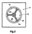
- the shutoff valve 13 comprises a generally conical plug 41 movable into or out of the discharge opening 27, and a vertical stem 42 extending straight upward from the upper end of the plug 41 and having an upper end integral with the lower end of the valve element 33.
- the stem 42 is provided with three radial guide vanes 43 extending from a lower portion of the stem 42 to the outer peripheral wall of the plug 41 and positioned at three locations dividing the plug 41 into three equal portions along the circumference thereof. As shown in detail in FIG. 2, each of the guide vanes 43 is provided at its outer end with a circular-arc guide face 44 in sliding contact with the inner surface of the nozzle body 11.
- the check valve 12 is opened with the pressure of the liquid. Simultaneously with this, the plug 41 is pushed down, discharging the liquid from the opening 27.
- FIG. 3 shows the shape of the plug 41 in detail.
- the plug 41 is provided at the lower end of its outer peripheral wall with an annular seal portion 51 shaped in conformity with the shape of the discharge opening 27.
- Extending upward from the seal portion 51 is an upwardly tapered spreader portion 52.
- the spreader portion 52 is in the form of a cone comprising an upper tapered part 61 and a lower tapered part 62.
- the upper tapered part 61 has an upper end diameter D1
- the upper tapered part 61 and the lower tapered part 62 have a boundary diameter D2
- the lower tapered part 62 has a lower end diameter D3
- the upper tapered part 61 has a height L1
- the lower tapered part 62 has a height L2.
- the taper (D2-D1)/L1 of the upper tapered part 61 is greater than the taper (D3-D2)/L2 of the lower tapered part 62
- the contour has an upper straight line M1 and a lower straight line M2.
- the angle ⁇ 1 the upper line M1 makes with a vertical is greater than the angle ⁇ 2 the lower line M2 makes with a vertical.
- FIG. 3(a) shows the state of the discharge opening 27 immediately after the start of a filling operation.
- the lower edge of the nozzle body 11 defining the discharge opening 27 is opposed to the lower tapered part 62.
- the liquid to be filled is discharged from between the lower edge defining the opening 27 and the lower tapered part 62 and spread along the outer surface of the lower tapered part 62.
- FIG. 3 (b) shows the discharge opening 27 as almost fully opened.
- the lower edge defining the discharge opening 27 is opposed to the upper tapered part 61 instead of the lower tapered part 62.
- the liquid to be filled spreads along the outer surface of the upper tapered part 61, the liquid is spread in a direction closer to a horizontal and as shifted from a direction close to a vertical.
- the liquid flow is guided closer to the downward direction in the state of FIG. 3(a) than in the state of FIG. 3(b).
- the liquid to be filled is less likely to be directed toward the wall of the container, and the upper edge portions of inner surface of the container to be sealed are unlikely to become wet with the liquid to be filled.
- the liquid is guided closer to a direction toward the container wall in the state of FIG. 3(b) than in the state of FIG. 3(a). Consequently, the liquid is prevented from impinging on the liquid surface gradually ascending with the progress of the filling operation.
- FIG. 4 shows a plug 41 of different shape. Like the plug already described, this plug 41 comprises a seal portion 51 and a spreader portion 52. The spreader portion 52 comprises a paraboloid of revolution.
- FIG. 4 shows an upper straight line N1 and a lower straight line N2.
- the upper line N1 is a tangent line at an upper reference point 01.
- the lower line N2 is a tangent line at a lower reference point 02.
- the upper line N1 and the lower line N2 correspond to the lines M1, M2, respectively.
- the angle ⁇ 1 the upper line N1 makes with a vertical is greater than the angle ⁇ 2 the lower line N2 makes with a vertical.
Landscapes
- Engineering & Computer Science (AREA)
- Mechanical Engineering (AREA)
- Filling Of Jars Or Cans And Processes For Cleaning And Sealing Jars (AREA)
- Supply Of Fluid Materials To The Packaging Location (AREA)
- Nozzles (AREA)
- Lubricants (AREA)
Abstract
Description
Claims (6)
- A liquid filling nozzle comprising a vertical tubular nozzle body having a discharge opening at a lower end thereof, and an upwardly or downwardly movable plug for opening or closing the discharge opening, the plug being provided with a seal portion disposed at a lower end of an outer peripheral wall thereof and shaped in conformity with the shape of the discharge opening, the seal portion being provided with a spreader portion positioned thereabove and tapered upward, the spreader portion being so shaped that the liquid to be filled and discharged from the opening is cause to spread by the spreader portion toward a direction closer to a horizontal and as shifted from a direction close to a vertical, as the seal portion is moved away from the discharge opening.
- A liquid filling nozzle according to claim 1 wherein in the contour of one side of a vertical longitudinal section of the spreader portion, tangent lines at respective reference points arranged on the spreader portion from above downward are positioned closer to a vertical from point to point downward.
- A liquid filling nozzle according to claim 2 wherein the reference points are two in number, and the contour is defined by two straight lines.
- A liquid filling nozzle according to claim 3 wherein the plug is in the form of a cone having two tapered parts positioned one above the other.
- A liquid filling nozzle according to claim 2 wherein the reference points are infinite in number, and the contour is defined by a curve.
- A liquid filling nozzle according to claim 5 wherein the plug is in the form of a paraboloid of revolution.
Applications Claiming Priority (2)
| Application Number | Priority Date | Filing Date | Title |
|---|---|---|---|
| JP2004124912A JP2005306427A (en) | 2004-04-21 | 2004-04-21 | Liquid filling nozzle |
| JP2004124912 | 2004-04-21 |
Publications (3)
| Publication Number | Publication Date |
|---|---|
| EP1588948A2 true EP1588948A2 (en) | 2005-10-26 |
| EP1588948A3 EP1588948A3 (en) | 2007-03-14 |
| EP1588948B1 EP1588948B1 (en) | 2010-03-31 |
Family
ID=34938177
Family Applications (1)
| Application Number | Title | Priority Date | Filing Date |
|---|---|---|---|
| EP05075894A Expired - Lifetime EP1588948B1 (en) | 2004-04-21 | 2005-04-15 | Liquid filling nozzle |
Country Status (6)
| Country | Link |
|---|---|
| EP (1) | EP1588948B1 (en) |
| JP (1) | JP2005306427A (en) |
| AT (1) | ATE462650T1 (en) |
| DE (1) | DE602005020207D1 (en) |
| DK (1) | DK1588948T3 (en) |
| ES (1) | ES2341967T3 (en) |
Cited By (3)
| Publication number | Priority date | Publication date | Assignee | Title |
|---|---|---|---|---|
| WO2008051151A1 (en) * | 2006-10-26 | 2008-05-02 | Ecolean Research & Development A/S | Device for filling of containers of collapsable type |
| WO2011092188A1 (en) | 2010-01-27 | 2011-08-04 | Elopak Systems Ag | Dosing device and dosing method for liquids |
| CN103241695A (en) * | 2013-05-17 | 2013-08-14 | 成都中牧生物药业有限公司 | Automated liquid medicine filling device |
Families Citing this family (2)
| Publication number | Priority date | Publication date | Assignee | Title |
|---|---|---|---|---|
| JP2008254775A (en) * | 2007-04-05 | 2008-10-23 | Nihon Tetra Pak Kk | Packaging and filling equipment |
| CN113896152B (en) * | 2021-11-08 | 2023-07-28 | 江门市铨胜涂料有限公司 | Automatic filling equipment of fire prevention coating production |
Family Cites Families (11)
| Publication number | Priority date | Publication date | Assignee | Title |
|---|---|---|---|---|
| US2788029A (en) * | 1953-08-31 | 1957-04-09 | Harold L Solie | Apparatus for filling bottles |
| NL6804735A (en) * | 1968-04-04 | 1969-10-07 | ||
| JPS4811972B1 (en) * | 1968-10-15 | 1973-04-17 | ||
| JPS563895U (en) * | 1979-06-21 | 1981-01-14 | ||
| DE3238625C1 (en) * | 1982-10-19 | 1984-08-16 | Rationator-Maschinenbau Gmbh, 6521 Hillesheim | Filler tube closure for filling machines |
| JPS59188899U (en) * | 1983-06-03 | 1984-12-14 | 三菱重工業株式会社 | Filling equipment for different types of containers |
| ZA915594B (en) * | 1990-08-13 | 1993-03-31 | Colgate Palmolive Co | Package filling method and apparatus |
| JP2531565Y2 (en) * | 1990-10-15 | 1997-04-02 | 四国化工機株式会社 | Liquid filling nozzle for square container |
| JPH06329103A (en) * | 1993-05-19 | 1994-11-29 | Oval Corp | Filling nozzle |
| JPH0958615A (en) * | 1995-08-25 | 1997-03-04 | Toyo Jidoki Co Ltd | Liquid filling nozzle |
| DE50204173D1 (en) * | 2002-02-20 | 2005-10-13 | Bmh Chronos Richardson Gmbh | Method and device for dosing bulk material |
-
2004
- 2004-04-21 JP JP2004124912A patent/JP2005306427A/en active Pending
-
2005
- 2005-04-15 DK DK05075894.5T patent/DK1588948T3/en active
- 2005-04-15 ES ES05075894T patent/ES2341967T3/en not_active Expired - Lifetime
- 2005-04-15 EP EP05075894A patent/EP1588948B1/en not_active Expired - Lifetime
- 2005-04-15 AT AT05075894T patent/ATE462650T1/en not_active IP Right Cessation
- 2005-04-15 DE DE602005020207T patent/DE602005020207D1/en not_active Expired - Lifetime
Cited By (8)
| Publication number | Priority date | Publication date | Assignee | Title |
|---|---|---|---|---|
| WO2008051151A1 (en) * | 2006-10-26 | 2008-05-02 | Ecolean Research & Development A/S | Device for filling of containers of collapsable type |
| EA014797B1 (en) * | 2006-10-26 | 2011-02-28 | Эколин Рисерч Энд Дивелопмент А/С | Device for filling containers of collapsible type |
| US8167007B2 (en) | 2006-10-26 | 2012-05-01 | Ecolean Research & Development A/S | Device for filling containers of collapsible type |
| AU2007309774B2 (en) * | 2006-10-26 | 2012-08-16 | Ecolean Ab | Device for filling of containers of collapsible type |
| KR101443186B1 (en) * | 2006-10-26 | 2014-09-23 | 에코린 에이비 | A device for filling a foldable container |
| WO2011092188A1 (en) | 2010-01-27 | 2011-08-04 | Elopak Systems Ag | Dosing device and dosing method for liquids |
| US10472218B2 (en) | 2010-01-27 | 2019-11-12 | Elopak Systems Ag | Dosing device and dosing method for liquids |
| CN103241695A (en) * | 2013-05-17 | 2013-08-14 | 成都中牧生物药业有限公司 | Automated liquid medicine filling device |
Also Published As
| Publication number | Publication date |
|---|---|
| ES2341967T3 (en) | 2010-06-30 |
| JP2005306427A (en) | 2005-11-04 |
| DK1588948T3 (en) | 2010-06-07 |
| DE602005020207D1 (en) | 2010-05-12 |
| EP1588948A3 (en) | 2007-03-14 |
| EP1588948B1 (en) | 2010-03-31 |
| ATE462650T1 (en) | 2010-04-15 |
Similar Documents
| Publication | Publication Date | Title |
|---|---|---|
| RU2224703C2 (en) | Aerosol valve | |
| JP5733752B2 (en) | Pump device | |
| CA2837636C (en) | Pumping device for a fluid container | |
| MXPA04005848A (en) | Aerosol powder valve. | |
| US5560522A (en) | Push opened valve for dispensing liquids | |
| US6409055B1 (en) | Filling valve | |
| EP3297956B1 (en) | Water purification device | |
| US6123236A (en) | Pump dispenser having one-piece spring and gasket | |
| US20190152754A1 (en) | Filling valve and liquid filling method | |
| US6332482B1 (en) | Multi-refillable spray can, device for filling said cans and method for producing said spray cans | |
| EP1588948B1 (en) | Liquid filling nozzle | |
| JP2000186781A (en) | Valve for discharging pressurized liquid, container provided with this valve, and method for manufacturing the container | |
| TW201311369A (en) | Container cleaner | |
| US3285300A (en) | Filling valve | |
| US1429566A (en) | Benner h | |
| JP2016069052A (en) | Liquid discharge container capable of pump operation and squeezing operation | |
| US5896897A (en) | Filling valve | |
| US3334668A (en) | Filler for charging containers | |
| US2187787A (en) | Valve | |
| JPS62287869A (en) | Cuppy body of valve and method of inserting cuppy body | |
| CN211111003U (en) | Filling and defoaming device for duplex pneumatic valve | |
| US3447779A (en) | Sanitary valve and nozzle assembly for pressure dispensers | |
| JPS58216587A (en) | Vessel filler | |
| US20140096866A1 (en) | Tipless can filling valve | |
| JPH0318321Y2 (en) |
Legal Events
| Date | Code | Title | Description |
|---|---|---|---|
| PUAI | Public reference made under article 153(3) epc to a published international application that has entered the european phase |
Free format text: ORIGINAL CODE: 0009012 |
|
| AK | Designated contracting states |
Kind code of ref document: A2 Designated state(s): AT BE BG CH CY CZ DE DK EE ES FI FR GB GR HU IE IS IT LI LT LU MC NL PL PT RO SE SI SK TR |
|
| AX | Request for extension of the european patent |
Extension state: AL BA HR LV MK YU |
|
| PUAL | Search report despatched |
Free format text: ORIGINAL CODE: 0009013 |
|
| AK | Designated contracting states |
Kind code of ref document: A3 Designated state(s): AT BE BG CH CY CZ DE DK EE ES FI FR GB GR HU IE IS IT LI LT LU MC NL PL PT RO SE SI SK TR |
|
| AX | Request for extension of the european patent |
Extension state: AL BA HR LV MK YU |
|
| 17P | Request for examination filed |
Effective date: 20070913 |
|
| AKX | Designation fees paid |
Designated state(s): AT BE BG CH CY CZ DE DK EE ES FI FR GB GR HU IE IS IT LI LT LU MC NL PL PT RO SE SI SK TR |
|
| 17Q | First examination report despatched |
Effective date: 20090116 |
|
| R17C | First examination report despatched (corrected) |
Effective date: 20090202 |
|
| GRAP | Despatch of communication of intention to grant a patent |
Free format text: ORIGINAL CODE: EPIDOSNIGR1 |
|
| RIN1 | Information on inventor provided before grant (corrected) |
Inventor name: MASAKATSU, KONDO |
|
| GRAS | Grant fee paid |
Free format text: ORIGINAL CODE: EPIDOSNIGR3 |
|
| GRAA | (expected) grant |
Free format text: ORIGINAL CODE: 0009210 |
|
| AK | Designated contracting states |
Kind code of ref document: B1 Designated state(s): AT BE BG CH CY CZ DE DK EE ES FI FR GB GR HU IE IS IT LI LT LU MC NL PL PT RO SE SI SK TR |
|
| REG | Reference to a national code |
Ref country code: GB Ref legal event code: FG4D Ref country code: CH Ref legal event code: EP |
|
| REG | Reference to a national code |
Ref country code: IE Ref legal event code: FG4D |
|
| REF | Corresponds to: |
Ref document number: 602005020207 Country of ref document: DE Date of ref document: 20100512 Kind code of ref document: P |
|
| REG | Reference to a national code |
Ref country code: SE Ref legal event code: TRGR |
|
| REG | Reference to a national code |
Ref country code: DK Ref legal event code: T3 |
|
| REG | Reference to a national code |
Ref country code: NL Ref legal event code: T3 |
|
| REG | Reference to a national code |
Ref country code: ES Ref legal event code: FG2A Ref document number: 2341967 Country of ref document: ES Kind code of ref document: T3 |
|
| PG25 | Lapsed in a contracting state [announced via postgrant information from national office to epo] |
Ref country code: LT Free format text: LAPSE BECAUSE OF FAILURE TO SUBMIT A TRANSLATION OF THE DESCRIPTION OR TO PAY THE FEE WITHIN THE PRESCRIBED TIME-LIMIT Effective date: 20100331 |
|
| LTIE | Lt: invalidation of european patent or patent extension |
Effective date: 20100331 |
|
| PG25 | Lapsed in a contracting state [announced via postgrant information from national office to epo] |
Ref country code: FI Free format text: LAPSE BECAUSE OF FAILURE TO SUBMIT A TRANSLATION OF THE DESCRIPTION OR TO PAY THE FEE WITHIN THE PRESCRIBED TIME-LIMIT Effective date: 20100331 Ref country code: AT Free format text: LAPSE BECAUSE OF FAILURE TO SUBMIT A TRANSLATION OF THE DESCRIPTION OR TO PAY THE FEE WITHIN THE PRESCRIBED TIME-LIMIT Effective date: 20100331 Ref country code: PL Free format text: LAPSE BECAUSE OF FAILURE TO SUBMIT A TRANSLATION OF THE DESCRIPTION OR TO PAY THE FEE WITHIN THE PRESCRIBED TIME-LIMIT Effective date: 20100331 Ref country code: SI Free format text: LAPSE BECAUSE OF FAILURE TO SUBMIT A TRANSLATION OF THE DESCRIPTION OR TO PAY THE FEE WITHIN THE PRESCRIBED TIME-LIMIT Effective date: 20100331 |
|
| PG25 | Lapsed in a contracting state [announced via postgrant information from national office to epo] |
Ref country code: CY Free format text: LAPSE BECAUSE OF FAILURE TO SUBMIT A TRANSLATION OF THE DESCRIPTION OR TO PAY THE FEE WITHIN THE PRESCRIBED TIME-LIMIT Effective date: 20100331 Ref country code: BE Free format text: LAPSE BECAUSE OF FAILURE TO SUBMIT A TRANSLATION OF THE DESCRIPTION OR TO PAY THE FEE WITHIN THE PRESCRIBED TIME-LIMIT Effective date: 20100331 Ref country code: EE Free format text: LAPSE BECAUSE OF FAILURE TO SUBMIT A TRANSLATION OF THE DESCRIPTION OR TO PAY THE FEE WITHIN THE PRESCRIBED TIME-LIMIT Effective date: 20100331 Ref country code: RO Free format text: LAPSE BECAUSE OF FAILURE TO SUBMIT A TRANSLATION OF THE DESCRIPTION OR TO PAY THE FEE WITHIN THE PRESCRIBED TIME-LIMIT Effective date: 20100331 |
|
| PG25 | Lapsed in a contracting state [announced via postgrant information from national office to epo] |
Ref country code: SK Free format text: LAPSE BECAUSE OF FAILURE TO SUBMIT A TRANSLATION OF THE DESCRIPTION OR TO PAY THE FEE WITHIN THE PRESCRIBED TIME-LIMIT Effective date: 20100331 Ref country code: CZ Free format text: LAPSE BECAUSE OF FAILURE TO SUBMIT A TRANSLATION OF THE DESCRIPTION OR TO PAY THE FEE WITHIN THE PRESCRIBED TIME-LIMIT Effective date: 20100331 Ref country code: IS Free format text: LAPSE BECAUSE OF FAILURE TO SUBMIT A TRANSLATION OF THE DESCRIPTION OR TO PAY THE FEE WITHIN THE PRESCRIBED TIME-LIMIT Effective date: 20100731 Ref country code: MC Free format text: LAPSE BECAUSE OF NON-PAYMENT OF DUE FEES Effective date: 20100430 |
|
| REG | Reference to a national code |
Ref country code: CH Ref legal event code: PL |
|
| PG25 | Lapsed in a contracting state [announced via postgrant information from national office to epo] |
Ref country code: IE Free format text: LAPSE BECAUSE OF NON-PAYMENT OF DUE FEES Effective date: 20100415 Ref country code: PT Free format text: LAPSE BECAUSE OF FAILURE TO SUBMIT A TRANSLATION OF THE DESCRIPTION OR TO PAY THE FEE WITHIN THE PRESCRIBED TIME-LIMIT Effective date: 20100802 |
|
| PLBE | No opposition filed within time limit |
Free format text: ORIGINAL CODE: 0009261 |
|
| STAA | Information on the status of an ep patent application or granted ep patent |
Free format text: STATUS: NO OPPOSITION FILED WITHIN TIME LIMIT |
|
| GBPC | Gb: european patent ceased through non-payment of renewal fee |
Effective date: 20100630 |
|
| PG25 | Lapsed in a contracting state [announced via postgrant information from national office to epo] |
Ref country code: LI Free format text: LAPSE BECAUSE OF NON-PAYMENT OF DUE FEES Effective date: 20100430 Ref country code: CH Free format text: LAPSE BECAUSE OF NON-PAYMENT OF DUE FEES Effective date: 20100430 |
|
| 26N | No opposition filed |
Effective date: 20110104 |
|
| PG25 | Lapsed in a contracting state [announced via postgrant information from national office to epo] |
Ref country code: IT Free format text: LAPSE BECAUSE OF FAILURE TO SUBMIT A TRANSLATION OF THE DESCRIPTION OR TO PAY THE FEE WITHIN THE PRESCRIBED TIME-LIMIT Effective date: 20100331 |
|
| PG25 | Lapsed in a contracting state [announced via postgrant information from national office to epo] |
Ref country code: GB Free format text: LAPSE BECAUSE OF NON-PAYMENT OF DUE FEES Effective date: 20100630 |
|
| REG | Reference to a national code |
Ref country code: FR Ref legal event code: ST Effective date: 20111125 |
|
| PG25 | Lapsed in a contracting state [announced via postgrant information from national office to epo] |
Ref country code: FR Free format text: LAPSE BECAUSE OF NON-PAYMENT OF DUE FEES Effective date: 20100531 |
|
| PG25 | Lapsed in a contracting state [announced via postgrant information from national office to epo] |
Ref country code: BG Free format text: LAPSE BECAUSE OF FAILURE TO SUBMIT A TRANSLATION OF THE DESCRIPTION OR TO PAY THE FEE WITHIN THE PRESCRIBED TIME-LIMIT Effective date: 20100331 Ref country code: HU Free format text: LAPSE BECAUSE OF FAILURE TO SUBMIT A TRANSLATION OF THE DESCRIPTION OR TO PAY THE FEE WITHIN THE PRESCRIBED TIME-LIMIT Effective date: 20101001 Ref country code: LU Free format text: LAPSE BECAUSE OF NON-PAYMENT OF DUE FEES Effective date: 20100415 |
|
| PG25 | Lapsed in a contracting state [announced via postgrant information from national office to epo] |
Ref country code: TR Free format text: LAPSE BECAUSE OF FAILURE TO SUBMIT A TRANSLATION OF THE DESCRIPTION OR TO PAY THE FEE WITHIN THE PRESCRIBED TIME-LIMIT Effective date: 20100331 |
|
| PGFP | Annual fee paid to national office [announced via postgrant information from national office to epo] |
Ref country code: ES Payment date: 20120425 Year of fee payment: 8 |
|
| PGFP | Annual fee paid to national office [announced via postgrant information from national office to epo] |
Ref country code: SE Payment date: 20130418 Year of fee payment: 9 |
|
| PG25 | Lapsed in a contracting state [announced via postgrant information from national office to epo] |
Ref country code: BG Free format text: LAPSE BECAUSE OF FAILURE TO SUBMIT A TRANSLATION OF THE DESCRIPTION OR TO PAY THE FEE WITHIN THE PRESCRIBED TIME-LIMIT Effective date: 20100630 |
|
| PG25 | Lapsed in a contracting state [announced via postgrant information from national office to epo] |
Ref country code: GR Free format text: LAPSE BECAUSE OF FAILURE TO SUBMIT A TRANSLATION OF THE DESCRIPTION OR TO PAY THE FEE WITHIN THE PRESCRIBED TIME-LIMIT Effective date: 20100331 |
|
| REG | Reference to a national code |
Ref country code: SE Ref legal event code: EUG |
|
| PG25 | Lapsed in a contracting state [announced via postgrant information from national office to epo] |
Ref country code: SE Free format text: LAPSE BECAUSE OF NON-PAYMENT OF DUE FEES Effective date: 20140416 |
|
| REG | Reference to a national code |
Ref country code: ES Ref legal event code: FD2A Effective date: 20150527 |
|
| PGFP | Annual fee paid to national office [announced via postgrant information from national office to epo] |
Ref country code: NL Payment date: 20150420 Year of fee payment: 11 |
|
| PG25 | Lapsed in a contracting state [announced via postgrant information from national office to epo] |
Ref country code: ES Free format text: LAPSE BECAUSE OF NON-PAYMENT OF DUE FEES Effective date: 20140416 |
|
| PGFP | Annual fee paid to national office [announced via postgrant information from national office to epo] |
Ref country code: DK Payment date: 20150420 Year of fee payment: 11 Ref country code: DE Payment date: 20150421 Year of fee payment: 11 |
|
| REG | Reference to a national code |
Ref country code: DE Ref legal event code: R119 Ref document number: 602005020207 Country of ref document: DE |
|
| REG | Reference to a national code |
Ref country code: DK Ref legal event code: EBP Effective date: 20160430 |
|
| REG | Reference to a national code |
Ref country code: NL Ref legal event code: MM Effective date: 20160501 |
|
| PG25 | Lapsed in a contracting state [announced via postgrant information from national office to epo] |
Ref country code: DE Free format text: LAPSE BECAUSE OF NON-PAYMENT OF DUE FEES Effective date: 20161101 Ref country code: NL Free format text: LAPSE BECAUSE OF NON-PAYMENT OF DUE FEES Effective date: 20160501 |
|
| PG25 | Lapsed in a contracting state [announced via postgrant information from national office to epo] |
Ref country code: DK Free format text: LAPSE BECAUSE OF NON-PAYMENT OF DUE FEES Effective date: 20160430 |