EP1588902A1 - Collision energy-absorbing element - Google Patents
Collision energy-absorbing element Download PDFInfo
- Publication number
- EP1588902A1 EP1588902A1 EP05075960A EP05075960A EP1588902A1 EP 1588902 A1 EP1588902 A1 EP 1588902A1 EP 05075960 A EP05075960 A EP 05075960A EP 05075960 A EP05075960 A EP 05075960A EP 1588902 A1 EP1588902 A1 EP 1588902A1
- Authority
- EP
- European Patent Office
- Prior art keywords
- deformation
- side walls
- element according
- section
- bumper support
- Prior art date
- Legal status (The legal status is an assumption and is not a legal conclusion. Google has not performed a legal analysis and makes no representation as to the accuracy of the status listed.)
- Granted
Links
- 230000002093 peripheral effect Effects 0.000 claims abstract description 4
- 230000007704 transition Effects 0.000 claims description 27
- 230000002787 reinforcement Effects 0.000 claims description 8
- 230000007423 decrease Effects 0.000 description 4
- 230000000694 effects Effects 0.000 description 2
- 238000005452 bending Methods 0.000 description 1
- 230000003247 decreasing effect Effects 0.000 description 1
- 238000006073 displacement reaction Methods 0.000 description 1
Images
Classifications
-
- B—PERFORMING OPERATIONS; TRANSPORTING
- B62—LAND VEHICLES FOR TRAVELLING OTHERWISE THAN ON RAILS
- B62D—MOTOR VEHICLES; TRAILERS
- B62D21/00—Understructures, i.e. chassis frame on which a vehicle body may be mounted
- B62D21/15—Understructures, i.e. chassis frame on which a vehicle body may be mounted having impact absorbing means, e.g. a frame designed to permanently or temporarily change shape or dimension upon impact with another body
Definitions
- the invention relates to a collision energy-absorbing element for use as a vehicle component, which element essentially has the shape of a tubular beam with a peripheral wall which is closed in cross-section, which beam has only one chamber, which has a front, a rear, two side walls and two ends, the front of the beam being directed away from the vehicle when the element is being used as a vehicle component, so that a force acting on the front leads to the deformation of the element in case of a collision.
- the invention also relates to the use of such an element in a vehicle component and to an element of this type.
- Collision energy-absorbing elements are known per se. They are used, for example, as crash boxes between the bumper and the front longitudinals of the vehicle body. However, the amount of collision energy which such crash boxes are able to absorb is small as there is little space available.
- the bumper which is described in this document is composed of an inwardly directed section made from a material of relatively high strength and an outwardly directed section of relatively low strength.
- the high-strength material imparts a stiffness to that section of the bumper which is sufficient to prevent bending and thus damage to the vehicle when a collision at low speed occurs.
- the outwardly directed section should deform in the case of a collision and absorb the collision energy.
- a collision energy-absorbing element for use as a vehicle component, as described in the introduction, the beam having a cross-section such that on deformation the beam passes through at least two deformation zones, each of which requires a maximum deformation force, before, in an end zone at complete deformation, the beam requires a deformation force which only increases.
- the element according to the invention thus provides a deformation zone which, after a first maximum deformation force, also has a second maximum deformation force.
- the amount of collision energy which the element can absorb is increased by means of the second deformation zone with the second maximum deformation force. This also makes it possible to prevent the element from having to deform completely, which would greatly increase the collision force.
- the maximum deformation force of the second deformation zone is higher than the maximum deformation force of the first deformation zone. This is especially advantageous in view of the demands made on vehicles with respect to the safety of pedestrians, which mean that the deformation force has to be low at low speeds of the vehicle. In order nevertheless to be able to absorb sufficient collision energy at high speeds, it is highly advantageous that the maximum deformation force of the second deformation zone is higher than the maximum deformation force of the first deformation zone.
- the second deformation zone is longer than the first deformation zone.
- the side walls of the beam have a transition section, as a result of which the distance between the side walls gradually changes in such a manner that the side walls on one side of the transition sections are at a greater distance from one another and the side walls on the other side of the transition sections are at a smaller distance from one another.
- the side walls will deform inwards locally by the effect of a deformation force, which creates the first deformation zone, and the remaining sections of the side walls will only deform later, which creates the second deformation zone.
- the transition sections in the side walls are at an angle to the adjoining sections of the side walls which is greater than 90°.
- this angle is an angle of between 120° and 150°, preferably approximately 135°.
- the side walls on both sides of the transition sections are substantially parallel to one another, preferably at an angle to one another of at most 10°.
- the sections of the side walls which are at a greater distance from one another are shorter than the sections of the side walls which are at a smaller distance from one another.
- the sections of the side walls which are at a greater distance from one another will deform first, following which the longer sections which are at a smaller distance from one another provide a long second deformation zone.
- the front of the beam and the rear of the beam are of different width, so that the beam has a relatively wide side and a relatively narrow side.
- the side walls can run substantially parallel to one another (except for the transition sections).
- a deformable material is present at the transition sections of the side walls between the side walls. This deformable material supports the side walls, as a result of which the side walls require a higher deformation force.
- the beam is provided with a reinforcement over a section of the cross-section at the front or the rear.
- this reinforcement ensures that the element absorbs collision energy over a large part of its length; the reinforcement itself may also deform and absorb collision energy.
- one or both ends of the beam are at least partly closed off by a deformable material.
- an additional element for absorbing deformation energy is provided at these ends.
- the invention also relates to the use of a collision energy-absorbing element as described above as part of a longitudinal member or sill, A-pillar, B-pillar, C-pillar, D-pillar, E-pillar, bumper support, door reinforcement beam or seat part of a vehicle.
- vehicle components should be able to absorb collision energy in order to protect the vehicle occupants.
- a collision energy-absorbing element which can absorb a relatively large amount of collision energy is thus desirable.
- the invention relates to a bumper support of a vehicle provided with a collision energy-absorbing element as described above, in which the bumper support comprises the energy-absorbing element over at least part of its length.
- the energy-absorbing element may then, for example, be situated in front of the front longitudinals, while the intermediate section is designed to be stiff.
- the bumper support comprises the energy-absorbing element over its entire length. This makes it possible to absorb the maximum amount of energy in the case of a collision.
- the front section of the beam passes through the first deformation zone.
- the rear of the bumper support may in that case be provided with a reinforcement, the bumper support being able to deform freely.
- the rear section of the beam passes through the first deformation zone. This is advantageous if the front of the bumper support is reinforced.
- the ends of the bumper support comprise an energy-absorbing element.
- the ends of the bumper support can absorb additional collision energy.
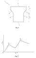
- Fig. 1 shows a cross-section of a collision energy-absorbing element 1 in the shape of a tubular beam.
- the element has a front 2, a rear 3 and side walls 4 and 5.
- the element is shaped in such a manner that the front 2 is of larger width than the rear 3, as a result of which the sections of the side wall 4 on both sides of the transition section 6 run substantially parallel to the sections of the side wall 5 on both sides of the transition section 7.
- the transition sections 6, 7 are at an angle of approximately 135° to the adjoining sections of the side walls 4, 5.
- the tubular beam forms one chamber having a closed peripheral wall.
- the element is preferably produced by hydroforming from a tube having a simple geometric cross section, such as a round tube.
- a tube having a simple geometric cross section such as a round tube.
- the corners of the various sides or sections thereof will in that case not be sharp, but slightly rounded.
- the element 1 in the shape of a tubular beam usually has a length which is greater than the width of the front 2 or the width of the side walls 4, 5. This is the case, for example, when the element 1 is used as a longitudinal member or sill, A-pillar, B-pillar, C-pillar, D-pillar, E-pillar, bumper support or door reinforcement beam of a vehicle; in all these cases, the tubular beam has a relatively great length.
- a collision energy-absorbing element may be used whose length is approximately equal to the width or the height.
- the collision energy-absorbing element according to the invention may likewise be used, the length of the element being approximately equal to the width of the front 2 or the width of the side walls 4, 5.
- the front 2 When the collision energy-absorbing element 1 is used as a bumper support of a vehicle, for instance the front 2 will be directed away from the vehicle. In the case of a collision, the front 2 then comes into contact with a collision object, as a result of which a force F is applied on the front 2, which causes an opposite reactive force F on the rear 3 of the element, causing the element 1 to be compressed.
- the side walls 4, 5 will be forced inwards, leading to their deformation at the location of the transition sections 6, 7.
- the transition sections 6, 7 move towards each other and will, depending on the width of the front 2 and the length a of the parallel sections of the side walls between the front 2 and the transition sections 6, 7 either touch each other or hit the inside of the front 2.
- This deformation forms a first deformation zone of the element 1, the deformation force initially increasing rapidly to reach a maximum value F1 and then decreasing again.
- the element in an end zone at complete deformation, will require a deformation force which increases again, as the element is in fact completely flattened.
- Fig. 2 The above situation is illustrated in Fig. 2, in which the force F is plotted against the distance s of the deformation zone.
- the first deformation zone in which the force initially increases to reach the value F1 and then decreases again can be clearly distinguished from the second deformation zone in which the force increases again to reach the value F2 and then decreases again.
- the amount of collision energy which is absorbed is determined by the area below the line of force in Fig. 2.
- the end zone in which the deformation force increases again is not shown in Fig. 2.
- the deformation zone can readily be influenced with the aid of the collision energy-absorbing element 1 by varying the lengths a and b of the side walls, the width of the front 2 and rear 3, and the length and angle of the transition sections 6, 7.
- the degree of parallelity of the side walls and the curvature of the sides will have an effect as well.
Landscapes
- Engineering & Computer Science (AREA)
- Chemical & Material Sciences (AREA)
- Combustion & Propulsion (AREA)
- Transportation (AREA)
- Mechanical Engineering (AREA)
- Body Structure For Vehicles (AREA)
- Vibration Dampers (AREA)
- Solid-Sorbent Or Filter-Aiding Compositions (AREA)
- Saccharide Compounds (AREA)
Abstract
Description
Claims (17)
- Collision energy-absorbing element for use as a vehicle component, which element essentially has the shape of a tubular beam with a peripheral wall which is closed in cross-section, which beam has one chamber, which has a front, a rear, two side walls and two ends, the front of the beam being directed away from the vehicle when the element is being used as a vehicle component, so that a force acting on the front leads to the deformation of the element in case of a collision, characterized in that the beam has a cross-section such that on deformation the beam passes through at least two deformation zones, each of which requires a maximum deformation force, before, in an end zone at complete deformation, the beam requires a deformation force which only increases.
- Element according to Claim 1, in which the maximum deformation force of the second deformation zone is higher than the maximum deformation force of the first deformation zone.
- Element according to Claim 1 or 2, in which the second deformation zone is longer than the first deformation zone.
- Element according to Claim 1, 2 or 3, in which, in sectional view, the side walls of the beam have a transition section, as a result of which the distance between the side walls gradually changes in such a manner that the side walls on one side of the transition sections are at a greater distance from one another and the side walls on the other side of the transition sections are at a smaller distance from one another.
- Element according to Claim 4, in which the transition sections in the side walls are at an angle to the adjoining sections of the side walls which is greater than 90°.
- Element according to Claim 4 or 5, in which the side walls on both sides of the transition sections are substantially parallel to one another, preferably at an angle to one another of at most 10°.
- Element according to Claims 4 - 6, in which the sections of the side walls which are at a greater distance from one another are shorter than the sections of the side walls which are at a smaller distance from one another.
- Element according to one of Claims 4 - 7, in which the front of the beam and the rear of the beam are of different width, so that the beam has a relatively wide side and a relatively narrow side.
- Element according to one of Claims 4 - 8, in which a deformable material is present at the transition sections of the side walls between the side walls.
- Element according to one of Claims 1 - 9, in which the beam is provided with a reinforcement over a section of the cross-section at the front or the rear.
- Element according to one of Claims 1 - 10, in which one or both ends of the beam are at least partly closed off by a deformable material.
- Use of an energy-absorbing element according to one of Claims 1 - 11 as part of a longitudinal member or sill, A-pillar, B-pillar, C-pillar, D-pillar, E-pillar, bumper support, door reinforcement beam or seat part of a vehicle.
- Bumper support of a vehicle provided with a collision energy-absorbing element according to one of Claims 1 - 11, in which the bumper support comprises the energy-absorbing element over at least part of its length.
- Bumper support according to Claim 13, in which the bumper support comprises the energy-absorbing element over its entire length.
- Bumper support according to Claim 14, in which the front section of the beam passes through the first deformation zone.
- Bumper support according to Claim 14, in which the rear section of the beam passes through the first deformation zone.
- Bumper support according to one of Claims 13 - 16, in which the ends of the bumper support comprise an energy-absorbing element.
Applications Claiming Priority (2)
| Application Number | Priority Date | Filing Date | Title |
|---|---|---|---|
| NL1026017 | 2004-04-23 | ||
| NL1026017A NL1026017C2 (en) | 2004-04-23 | 2004-04-23 | Collision energy absorbing element. |
Publications (2)
| Publication Number | Publication Date |
|---|---|
| EP1588902A1 true EP1588902A1 (en) | 2005-10-26 |
| EP1588902B1 EP1588902B1 (en) | 2008-11-05 |
Family
ID=34938208
Family Applications (1)
| Application Number | Title | Priority Date | Filing Date |
|---|---|---|---|
| EP05075960A Expired - Lifetime EP1588902B1 (en) | 2004-04-23 | 2005-04-22 | Collision energy-absorbing element |
Country Status (4)
| Country | Link |
|---|---|
| EP (1) | EP1588902B1 (en) |
| AT (1) | ATE413311T1 (en) |
| DE (1) | DE602005010779D1 (en) |
| NL (1) | NL1026017C2 (en) |
Families Citing this family (1)
| Publication number | Priority date | Publication date | Assignee | Title |
|---|---|---|---|---|
| DE102021114467A1 (en) | 2021-06-05 | 2022-12-08 | Ford Global Technologies Llc | Body pillar, in particular B-pillar, of a motor vehicle with inclined strength transition areas |
Citations (4)
| Publication number | Priority date | Publication date | Assignee | Title |
|---|---|---|---|---|
| DE19913078A1 (en) * | 1999-03-23 | 2000-09-28 | Bayerische Motoren Werke Ag | Vehicle bumper, located horizontally at the front and/or rear of the vehicle, has a crash box composed of at least two chambers. |
| US6138429A (en) | 1997-07-31 | 2000-10-31 | Dr. Ing. H. C. F. Porshe Ag | Cross member for vehicles and method of manufacturing same |
| EP1262374A1 (en) | 2001-05-29 | 2002-12-04 | Inalfa Industries B.V. | Crash energy absorbing element |
| DE10205627A1 (en) * | 2002-02-12 | 2003-08-14 | Suspa Holding Gmbh | Vehicle bumper, comprises hollow profile containing insert designed to deform in event of collison |
-
2004
- 2004-04-23 NL NL1026017A patent/NL1026017C2/en not_active IP Right Cessation
-
2005
- 2005-04-22 AT AT05075960T patent/ATE413311T1/en not_active IP Right Cessation
- 2005-04-22 DE DE602005010779T patent/DE602005010779D1/en not_active Expired - Lifetime
- 2005-04-22 EP EP05075960A patent/EP1588902B1/en not_active Expired - Lifetime
Patent Citations (4)
| Publication number | Priority date | Publication date | Assignee | Title |
|---|---|---|---|---|
| US6138429A (en) | 1997-07-31 | 2000-10-31 | Dr. Ing. H. C. F. Porshe Ag | Cross member for vehicles and method of manufacturing same |
| DE19913078A1 (en) * | 1999-03-23 | 2000-09-28 | Bayerische Motoren Werke Ag | Vehicle bumper, located horizontally at the front and/or rear of the vehicle, has a crash box composed of at least two chambers. |
| EP1262374A1 (en) | 2001-05-29 | 2002-12-04 | Inalfa Industries B.V. | Crash energy absorbing element |
| DE10205627A1 (en) * | 2002-02-12 | 2003-08-14 | Suspa Holding Gmbh | Vehicle bumper, comprises hollow profile containing insert designed to deform in event of collison |
Also Published As
| Publication number | Publication date |
|---|---|
| EP1588902B1 (en) | 2008-11-05 |
| NL1026017C2 (en) | 2005-10-25 |
| DE602005010779D1 (en) | 2008-12-18 |
| ATE413311T1 (en) | 2008-11-15 |
Similar Documents
| Publication | Publication Date | Title |
|---|---|---|
| JP5154229B2 (en) | Safety device | |
| US3998485A (en) | Bumper arrangement for a vehicle equipped with longitudinal members | |
| US7931318B2 (en) | Bumper attachment portion structure | |
| KR20060066111A (en) | Apparatus and method for increasing passenger protection in a vehicle during side impact | |
| GB2309945A (en) | Energy absorbing vehicle structure | |
| US20060237976A1 (en) | Crushable structure manufactured from mechanical expansion | |
| US6793246B2 (en) | Knee support for occupants | |
| US7275764B2 (en) | Vehicle occupant knee protection device | |
| US20150336526A1 (en) | Bumper arrangement for a motor vehicle | |
| US8353545B1 (en) | Compact energy absorbing vehicle crash structure | |
| US20130076051A1 (en) | Integrated Energy Absorbing Vehicle Crash Structure | |
| US20060082124A1 (en) | Vehicle front structure, activation controller for occupant protection apparatus, and method of production of vehicle front structure | |
| US6811185B2 (en) | Steering column for a motor vehicle | |
| US7441806B2 (en) | Knee bolster | |
| CN114375266A (en) | Vehicle bumper extension with crush box bracket | |
| US20020060463A1 (en) | Shock absorbing member and bumper | |
| CA2534653C (en) | Vehicle frame having energy management system and method for making same | |
| JP5011516B2 (en) | Shock absorber for vehicle | |
| EP1262374B1 (en) | Crash energy absorbing element | |
| JP2009154617A (en) | Under member structure for vehicles | |
| EP2543572B1 (en) | A Motor Vehicle Safety Device | |
| EP1588902B1 (en) | Collision energy-absorbing element | |
| JPH09277953A (en) | Shock absorbing member | |
| CA2310705C (en) | Production of a component for reducing the effects of an external mechanical impact, and the component produced in this way | |
| JP2889162B2 (en) | Energy absorption structure on the side of the vehicle |
Legal Events
| Date | Code | Title | Description |
|---|---|---|---|
| PUAI | Public reference made under article 153(3) epc to a published international application that has entered the european phase |
Free format text: ORIGINAL CODE: 0009012 |
|
| AK | Designated contracting states |
Kind code of ref document: A1 Designated state(s): AT BE BG CH CY CZ DE DK EE ES FI FR GB GR HU IE IS IT LI LT LU MC NL PL PT RO SE SI SK TR |
|
| AX | Request for extension of the european patent |
Extension state: AL BA HR LV MK YU |
|
| 17P | Request for examination filed |
Effective date: 20060426 |
|
| AKX | Designation fees paid |
Designated state(s): AT BE BG CH CY CZ DE DK EE ES FI FR GB GR HU IE IS IT LI LT LU MC NL PL PT RO SE SI SK TR |
|
| 17Q | First examination report despatched |
Effective date: 20070611 |
|
| GRAP | Despatch of communication of intention to grant a patent |
Free format text: ORIGINAL CODE: EPIDOSNIGR1 |
|
| GRAS | Grant fee paid |
Free format text: ORIGINAL CODE: EPIDOSNIGR3 |
|
| GRAA | (expected) grant |
Free format text: ORIGINAL CODE: 0009210 |
|
| AK | Designated contracting states |
Kind code of ref document: B1 Designated state(s): AT BE BG CH CY CZ DE DK EE ES FI FR GB GR HU IE IS IT LI LT LU MC NL PL PT RO SE SI SK TR |
|
| REG | Reference to a national code |
Ref country code: GB Ref legal event code: FG4D |
|
| REG | Reference to a national code |
Ref country code: CH Ref legal event code: EP |
|
| REG | Reference to a national code |
Ref country code: IE Ref legal event code: FG4D |
|
| REF | Corresponds to: |
Ref document number: 602005010779 Country of ref document: DE Date of ref document: 20081218 Kind code of ref document: P |
|
| REG | Reference to a national code |
Ref country code: SE Ref legal event code: TRGR |
|
| NLV1 | Nl: lapsed or annulled due to failure to fulfill the requirements of art. 29p and 29m of the patents act | ||
| LTIE | Lt: invalidation of european patent or patent extension |
Effective date: 20081105 |
|
| PG25 | Lapsed in a contracting state [announced via postgrant information from national office to epo] |
Ref country code: LT Free format text: LAPSE BECAUSE OF FAILURE TO SUBMIT A TRANSLATION OF THE DESCRIPTION OR TO PAY THE FEE WITHIN THE PRESCRIBED TIME-LIMIT Effective date: 20081105 Ref country code: AT Free format text: LAPSE BECAUSE OF FAILURE TO SUBMIT A TRANSLATION OF THE DESCRIPTION OR TO PAY THE FEE WITHIN THE PRESCRIBED TIME-LIMIT Effective date: 20081105 Ref country code: ES Free format text: LAPSE BECAUSE OF FAILURE TO SUBMIT A TRANSLATION OF THE DESCRIPTION OR TO PAY THE FEE WITHIN THE PRESCRIBED TIME-LIMIT Effective date: 20090216 |
|
| PG25 | Lapsed in a contracting state [announced via postgrant information from national office to epo] |
Ref country code: SI Free format text: LAPSE BECAUSE OF FAILURE TO SUBMIT A TRANSLATION OF THE DESCRIPTION OR TO PAY THE FEE WITHIN THE PRESCRIBED TIME-LIMIT Effective date: 20081105 Ref country code: FI Free format text: LAPSE BECAUSE OF FAILURE TO SUBMIT A TRANSLATION OF THE DESCRIPTION OR TO PAY THE FEE WITHIN THE PRESCRIBED TIME-LIMIT Effective date: 20081105 Ref country code: PL Free format text: LAPSE BECAUSE OF FAILURE TO SUBMIT A TRANSLATION OF THE DESCRIPTION OR TO PAY THE FEE WITHIN THE PRESCRIBED TIME-LIMIT Effective date: 20081105 Ref country code: NL Free format text: LAPSE BECAUSE OF FAILURE TO SUBMIT A TRANSLATION OF THE DESCRIPTION OR TO PAY THE FEE WITHIN THE PRESCRIBED TIME-LIMIT Effective date: 20081105 Ref country code: IS Free format text: LAPSE BECAUSE OF FAILURE TO SUBMIT A TRANSLATION OF THE DESCRIPTION OR TO PAY THE FEE WITHIN THE PRESCRIBED TIME-LIMIT Effective date: 20090305 |
|
| PG25 | Lapsed in a contracting state [announced via postgrant information from national office to epo] |
Ref country code: DK Free format text: LAPSE BECAUSE OF FAILURE TO SUBMIT A TRANSLATION OF THE DESCRIPTION OR TO PAY THE FEE WITHIN THE PRESCRIBED TIME-LIMIT Effective date: 20081105 Ref country code: RO Free format text: LAPSE BECAUSE OF FAILURE TO SUBMIT A TRANSLATION OF THE DESCRIPTION OR TO PAY THE FEE WITHIN THE PRESCRIBED TIME-LIMIT Effective date: 20081105 Ref country code: EE Free format text: LAPSE BECAUSE OF FAILURE TO SUBMIT A TRANSLATION OF THE DESCRIPTION OR TO PAY THE FEE WITHIN THE PRESCRIBED TIME-LIMIT Effective date: 20081105 Ref country code: BE Free format text: LAPSE BECAUSE OF FAILURE TO SUBMIT A TRANSLATION OF THE DESCRIPTION OR TO PAY THE FEE WITHIN THE PRESCRIBED TIME-LIMIT Effective date: 20081105 Ref country code: BG Free format text: LAPSE BECAUSE OF FAILURE TO SUBMIT A TRANSLATION OF THE DESCRIPTION OR TO PAY THE FEE WITHIN THE PRESCRIBED TIME-LIMIT Effective date: 20090205 |
|
| PG25 | Lapsed in a contracting state [announced via postgrant information from national office to epo] |
Ref country code: PT Free format text: LAPSE BECAUSE OF FAILURE TO SUBMIT A TRANSLATION OF THE DESCRIPTION OR TO PAY THE FEE WITHIN THE PRESCRIBED TIME-LIMIT Effective date: 20090406 Ref country code: CZ Free format text: LAPSE BECAUSE OF FAILURE TO SUBMIT A TRANSLATION OF THE DESCRIPTION OR TO PAY THE FEE WITHIN THE PRESCRIBED TIME-LIMIT Effective date: 20081105 |
|
| PLBE | No opposition filed within time limit |
Free format text: ORIGINAL CODE: 0009261 |
|
| STAA | Information on the status of an ep patent application or granted ep patent |
Free format text: STATUS: NO OPPOSITION FILED WITHIN TIME LIMIT |
|
| PG25 | Lapsed in a contracting state [announced via postgrant information from national office to epo] |
Ref country code: SK Free format text: LAPSE BECAUSE OF FAILURE TO SUBMIT A TRANSLATION OF THE DESCRIPTION OR TO PAY THE FEE WITHIN THE PRESCRIBED TIME-LIMIT Effective date: 20081105 |
|
| 26N | No opposition filed |
Effective date: 20090806 |
|
| REG | Reference to a national code |
Ref country code: CH Ref legal event code: PL |
|
| PG25 | Lapsed in a contracting state [announced via postgrant information from national office to epo] |
Ref country code: CH Free format text: LAPSE BECAUSE OF NON-PAYMENT OF DUE FEES Effective date: 20090430 Ref country code: LI Free format text: LAPSE BECAUSE OF NON-PAYMENT OF DUE FEES Effective date: 20090430 |
|
| PG25 | Lapsed in a contracting state [announced via postgrant information from national office to epo] |
Ref country code: MC Free format text: LAPSE BECAUSE OF NON-PAYMENT OF DUE FEES Effective date: 20090430 Ref country code: IE Free format text: LAPSE BECAUSE OF NON-PAYMENT OF DUE FEES Effective date: 20090422 |
|
| PG25 | Lapsed in a contracting state [announced via postgrant information from national office to epo] |
Ref country code: GR Free format text: LAPSE BECAUSE OF FAILURE TO SUBMIT A TRANSLATION OF THE DESCRIPTION OR TO PAY THE FEE WITHIN THE PRESCRIBED TIME-LIMIT Effective date: 20090206 |
|
| PG25 | Lapsed in a contracting state [announced via postgrant information from national office to epo] |
Ref country code: LU Free format text: LAPSE BECAUSE OF NON-PAYMENT OF DUE FEES Effective date: 20090422 |
|
| PG25 | Lapsed in a contracting state [announced via postgrant information from national office to epo] |
Ref country code: HU Free format text: LAPSE BECAUSE OF FAILURE TO SUBMIT A TRANSLATION OF THE DESCRIPTION OR TO PAY THE FEE WITHIN THE PRESCRIBED TIME-LIMIT Effective date: 20090506 |
|
| PG25 | Lapsed in a contracting state [announced via postgrant information from national office to epo] |
Ref country code: TR Free format text: LAPSE BECAUSE OF FAILURE TO SUBMIT A TRANSLATION OF THE DESCRIPTION OR TO PAY THE FEE WITHIN THE PRESCRIBED TIME-LIMIT Effective date: 20081105 |
|
| PG25 | Lapsed in a contracting state [announced via postgrant information from national office to epo] |
Ref country code: CY Free format text: LAPSE BECAUSE OF FAILURE TO SUBMIT A TRANSLATION OF THE DESCRIPTION OR TO PAY THE FEE WITHIN THE PRESCRIBED TIME-LIMIT Effective date: 20081105 |
|
| PGFP | Annual fee paid to national office [announced via postgrant information from national office to epo] |
Ref country code: DE Payment date: 20120427 Year of fee payment: 8 |
|
| PGFP | Annual fee paid to national office [announced via postgrant information from national office to epo] |
Ref country code: FR Payment date: 20120503 Year of fee payment: 8 Ref country code: SE Payment date: 20120427 Year of fee payment: 8 Ref country code: GB Payment date: 20120425 Year of fee payment: 8 |
|
| PGFP | Annual fee paid to national office [announced via postgrant information from national office to epo] |
Ref country code: IT Payment date: 20120423 Year of fee payment: 8 |
|
| REG | Reference to a national code |
Ref country code: SE Ref legal event code: EUG |
|
| GBPC | Gb: european patent ceased through non-payment of renewal fee |
Effective date: 20130422 |
|
| PG25 | Lapsed in a contracting state [announced via postgrant information from national office to epo] |
Ref country code: DE Free format text: LAPSE BECAUSE OF NON-PAYMENT OF DUE FEES Effective date: 20131101 Ref country code: GB Free format text: LAPSE BECAUSE OF NON-PAYMENT OF DUE FEES Effective date: 20130422 Ref country code: SE Free format text: LAPSE BECAUSE OF NON-PAYMENT OF DUE FEES Effective date: 20130423 |
|
| REG | Reference to a national code |
Ref country code: FR Ref legal event code: ST Effective date: 20131231 |
|
| REG | Reference to a national code |
Ref country code: DE Ref legal event code: R119 Ref document number: 602005010779 Country of ref document: DE Effective date: 20131101 |
|
| PG25 | Lapsed in a contracting state [announced via postgrant information from national office to epo] |
Ref country code: IT Free format text: LAPSE BECAUSE OF NON-PAYMENT OF DUE FEES Effective date: 20130422 Ref country code: FR Free format text: LAPSE BECAUSE OF NON-PAYMENT OF DUE FEES Effective date: 20130430 |