EP1588677A2 - Acetabular prosthesis - Google Patents
Acetabular prosthesis Download PDFInfo
- Publication number
- EP1588677A2 EP1588677A2 EP05252456A EP05252456A EP1588677A2 EP 1588677 A2 EP1588677 A2 EP 1588677A2 EP 05252456 A EP05252456 A EP 05252456A EP 05252456 A EP05252456 A EP 05252456A EP 1588677 A2 EP1588677 A2 EP 1588677A2
- Authority
- EP
- European Patent Office
- Prior art keywords
- acetabular component
- flanges
- cup
- component prosthesis
- pair
- Prior art date
- Legal status (The legal status is an assumption and is not a legal conclusion. Google has not performed a legal analysis and makes no representation as to the accuracy of the status listed.)
- Granted
Links
Images


Classifications
-
- A—HUMAN NECESSITIES
- A61—MEDICAL OR VETERINARY SCIENCE; HYGIENE
- A61B—DIAGNOSIS; SURGERY; IDENTIFICATION
- A61B17/00—Surgical instruments, devices or methods
- A61B17/56—Surgical instruments or methods for treatment of bones or joints; Devices specially adapted therefor
- A61B17/58—Surgical instruments or methods for treatment of bones or joints; Devices specially adapted therefor for osteosynthesis, e.g. bone plates, screws or setting implements
- A61B17/68—Internal fixation devices, including fasteners and spinal fixators, even if a part thereof projects from the skin
- A61B17/84—Fasteners therefor or fasteners being internal fixation devices
- A61B17/86—Pins or screws or threaded wires; nuts therefor
- A61B17/8625—Shanks, i.e. parts contacting bone tissue
- A61B17/8635—Tips of screws
-
- A—HUMAN NECESSITIES
- A61—MEDICAL OR VETERINARY SCIENCE; HYGIENE
- A61B—DIAGNOSIS; SURGERY; IDENTIFICATION
- A61B17/00—Surgical instruments, devices or methods
- A61B17/56—Surgical instruments or methods for treatment of bones or joints; Devices specially adapted therefor
- A61B17/58—Surgical instruments or methods for treatment of bones or joints; Devices specially adapted therefor for osteosynthesis, e.g. bone plates, screws or setting implements
- A61B17/68—Internal fixation devices, including fasteners and spinal fixators, even if a part thereof projects from the skin
- A61B17/84—Fasteners therefor or fasteners being internal fixation devices
- A61B17/86—Pins or screws or threaded wires; nuts therefor
- A61B17/8605—Heads, i.e. proximal ends projecting from bone
-
- A—HUMAN NECESSITIES
- A61—MEDICAL OR VETERINARY SCIENCE; HYGIENE
- A61F—FILTERS IMPLANTABLE INTO BLOOD VESSELS; PROSTHESES; DEVICES PROVIDING PATENCY TO, OR PREVENTING COLLAPSING OF, TUBULAR STRUCTURES OF THE BODY, e.g. STENTS; ORTHOPAEDIC, NURSING OR CONTRACEPTIVE DEVICES; FOMENTATION; TREATMENT OR PROTECTION OF EYES OR EARS; BANDAGES, DRESSINGS OR ABSORBENT PADS; FIRST-AID KITS
- A61F2/00—Filters implantable into blood vessels; Prostheses, i.e. artificial substitutes or replacements for parts of the body; Appliances for connecting them with the body; Devices providing patency to, or preventing collapsing of, tubular structures of the body, e.g. stents
- A61F2/02—Prostheses implantable into the body
- A61F2/30—Joints
- A61F2/32—Joints for the hip
- A61F2/34—Acetabular cups
-
- A—HUMAN NECESSITIES
- A61—MEDICAL OR VETERINARY SCIENCE; HYGIENE
- A61F—FILTERS IMPLANTABLE INTO BLOOD VESSELS; PROSTHESES; DEVICES PROVIDING PATENCY TO, OR PREVENTING COLLAPSING OF, TUBULAR STRUCTURES OF THE BODY, e.g. STENTS; ORTHOPAEDIC, NURSING OR CONTRACEPTIVE DEVICES; FOMENTATION; TREATMENT OR PROTECTION OF EYES OR EARS; BANDAGES, DRESSINGS OR ABSORBENT PADS; FIRST-AID KITS
- A61F2/00—Filters implantable into blood vessels; Prostheses, i.e. artificial substitutes or replacements for parts of the body; Appliances for connecting them with the body; Devices providing patency to, or preventing collapsing of, tubular structures of the body, e.g. stents
- A61F2/02—Prostheses implantable into the body
- A61F2/30—Joints
- A61F2002/30001—Additional features of subject-matter classified in A61F2/28, A61F2/30 and subgroups thereof
- A61F2002/30108—Shapes
- A61F2002/3011—Cross-sections or two-dimensional shapes
- A61F2002/30112—Rounded shapes, e.g. with rounded corners
- A61F2002/30136—Rounded shapes, e.g. with rounded corners undulated or wavy, e.g. serpentine-shaped or zigzag-shaped
-
- A—HUMAN NECESSITIES
- A61—MEDICAL OR VETERINARY SCIENCE; HYGIENE
- A61F—FILTERS IMPLANTABLE INTO BLOOD VESSELS; PROSTHESES; DEVICES PROVIDING PATENCY TO, OR PREVENTING COLLAPSING OF, TUBULAR STRUCTURES OF THE BODY, e.g. STENTS; ORTHOPAEDIC, NURSING OR CONTRACEPTIVE DEVICES; FOMENTATION; TREATMENT OR PROTECTION OF EYES OR EARS; BANDAGES, DRESSINGS OR ABSORBENT PADS; FIRST-AID KITS
- A61F2/00—Filters implantable into blood vessels; Prostheses, i.e. artificial substitutes or replacements for parts of the body; Appliances for connecting them with the body; Devices providing patency to, or preventing collapsing of, tubular structures of the body, e.g. stents
- A61F2/02—Prostheses implantable into the body
- A61F2/30—Joints
- A61F2002/30001—Additional features of subject-matter classified in A61F2/28, A61F2/30 and subgroups thereof
- A61F2002/30316—The prosthesis having different structural features at different locations within the same prosthesis; Connections between prosthetic parts; Special structural features of bone or joint prostheses not otherwise provided for
- A61F2002/30535—Special structural features of bone or joint prostheses not otherwise provided for
- A61F2002/30576—Special structural features of bone or joint prostheses not otherwise provided for with extending fixation tabs
-
- A—HUMAN NECESSITIES
- A61—MEDICAL OR VETERINARY SCIENCE; HYGIENE
- A61F—FILTERS IMPLANTABLE INTO BLOOD VESSELS; PROSTHESES; DEVICES PROVIDING PATENCY TO, OR PREVENTING COLLAPSING OF, TUBULAR STRUCTURES OF THE BODY, e.g. STENTS; ORTHOPAEDIC, NURSING OR CONTRACEPTIVE DEVICES; FOMENTATION; TREATMENT OR PROTECTION OF EYES OR EARS; BANDAGES, DRESSINGS OR ABSORBENT PADS; FIRST-AID KITS
- A61F2/00—Filters implantable into blood vessels; Prostheses, i.e. artificial substitutes or replacements for parts of the body; Appliances for connecting them with the body; Devices providing patency to, or preventing collapsing of, tubular structures of the body, e.g. stents
- A61F2/02—Prostheses implantable into the body
- A61F2/30—Joints
- A61F2002/30001—Additional features of subject-matter classified in A61F2/28, A61F2/30 and subgroups thereof
- A61F2002/30667—Features concerning an interaction with the environment or a particular use of the prosthesis
- A61F2002/30708—Means for distinguishing between left-sided and right-sided devices, Sets comprising both left-sided and right-sided prosthetic parts
-
- A—HUMAN NECESSITIES
- A61—MEDICAL OR VETERINARY SCIENCE; HYGIENE
- A61F—FILTERS IMPLANTABLE INTO BLOOD VESSELS; PROSTHESES; DEVICES PROVIDING PATENCY TO, OR PREVENTING COLLAPSING OF, TUBULAR STRUCTURES OF THE BODY, e.g. STENTS; ORTHOPAEDIC, NURSING OR CONTRACEPTIVE DEVICES; FOMENTATION; TREATMENT OR PROTECTION OF EYES OR EARS; BANDAGES, DRESSINGS OR ABSORBENT PADS; FIRST-AID KITS
- A61F2/00—Filters implantable into blood vessels; Prostheses, i.e. artificial substitutes or replacements for parts of the body; Appliances for connecting them with the body; Devices providing patency to, or preventing collapsing of, tubular structures of the body, e.g. stents
- A61F2/02—Prostheses implantable into the body
- A61F2/30—Joints
- A61F2002/30001—Additional features of subject-matter classified in A61F2/28, A61F2/30 and subgroups thereof
- A61F2002/30667—Features concerning an interaction with the environment or a particular use of the prosthesis
- A61F2002/3071—Identification means; Administration of patients
-
- A—HUMAN NECESSITIES
- A61—MEDICAL OR VETERINARY SCIENCE; HYGIENE
- A61F—FILTERS IMPLANTABLE INTO BLOOD VESSELS; PROSTHESES; DEVICES PROVIDING PATENCY TO, OR PREVENTING COLLAPSING OF, TUBULAR STRUCTURES OF THE BODY, e.g. STENTS; ORTHOPAEDIC, NURSING OR CONTRACEPTIVE DEVICES; FOMENTATION; TREATMENT OR PROTECTION OF EYES OR EARS; BANDAGES, DRESSINGS OR ABSORBENT PADS; FIRST-AID KITS
- A61F2/00—Filters implantable into blood vessels; Prostheses, i.e. artificial substitutes or replacements for parts of the body; Appliances for connecting them with the body; Devices providing patency to, or preventing collapsing of, tubular structures of the body, e.g. stents
- A61F2/02—Prostheses implantable into the body
- A61F2/30—Joints
- A61F2/30767—Special external or bone-contacting surface, e.g. coating for improving bone ingrowth
- A61F2002/30769—Special external or bone-contacting surface, e.g. coating for improving bone ingrowth madreporic
-
- A—HUMAN NECESSITIES
- A61—MEDICAL OR VETERINARY SCIENCE; HYGIENE
- A61F—FILTERS IMPLANTABLE INTO BLOOD VESSELS; PROSTHESES; DEVICES PROVIDING PATENCY TO, OR PREVENTING COLLAPSING OF, TUBULAR STRUCTURES OF THE BODY, e.g. STENTS; ORTHOPAEDIC, NURSING OR CONTRACEPTIVE DEVICES; FOMENTATION; TREATMENT OR PROTECTION OF EYES OR EARS; BANDAGES, DRESSINGS OR ABSORBENT PADS; FIRST-AID KITS
- A61F2/00—Filters implantable into blood vessels; Prostheses, i.e. artificial substitutes or replacements for parts of the body; Appliances for connecting them with the body; Devices providing patency to, or preventing collapsing of, tubular structures of the body, e.g. stents
- A61F2/02—Prostheses implantable into the body
- A61F2/30—Joints
- A61F2/30767—Special external or bone-contacting surface, e.g. coating for improving bone ingrowth
- A61F2/30771—Special external or bone-contacting surface, e.g. coating for improving bone ingrowth applied in original prostheses, e.g. holes or grooves
- A61F2002/30772—Apertures or holes, e.g. of circular cross section
- A61F2002/30774—Apertures or holes, e.g. of circular cross section internally-threaded
-
- A—HUMAN NECESSITIES
- A61—MEDICAL OR VETERINARY SCIENCE; HYGIENE
- A61F—FILTERS IMPLANTABLE INTO BLOOD VESSELS; PROSTHESES; DEVICES PROVIDING PATENCY TO, OR PREVENTING COLLAPSING OF, TUBULAR STRUCTURES OF THE BODY, e.g. STENTS; ORTHOPAEDIC, NURSING OR CONTRACEPTIVE DEVICES; FOMENTATION; TREATMENT OR PROTECTION OF EYES OR EARS; BANDAGES, DRESSINGS OR ABSORBENT PADS; FIRST-AID KITS
- A61F2/00—Filters implantable into blood vessels; Prostheses, i.e. artificial substitutes or replacements for parts of the body; Appliances for connecting them with the body; Devices providing patency to, or preventing collapsing of, tubular structures of the body, e.g. stents
- A61F2/02—Prostheses implantable into the body
- A61F2/30—Joints
- A61F2/30767—Special external or bone-contacting surface, e.g. coating for improving bone ingrowth
- A61F2/30771—Special external or bone-contacting surface, e.g. coating for improving bone ingrowth applied in original prostheses, e.g. holes or grooves
- A61F2002/30772—Apertures or holes, e.g. of circular cross section
- A61F2002/30784—Plurality of holes
- A61F2002/30785—Plurality of holes parallel
-
- A—HUMAN NECESSITIES
- A61—MEDICAL OR VETERINARY SCIENCE; HYGIENE
- A61F—FILTERS IMPLANTABLE INTO BLOOD VESSELS; PROSTHESES; DEVICES PROVIDING PATENCY TO, OR PREVENTING COLLAPSING OF, TUBULAR STRUCTURES OF THE BODY, e.g. STENTS; ORTHOPAEDIC, NURSING OR CONTRACEPTIVE DEVICES; FOMENTATION; TREATMENT OR PROTECTION OF EYES OR EARS; BANDAGES, DRESSINGS OR ABSORBENT PADS; FIRST-AID KITS
- A61F2/00—Filters implantable into blood vessels; Prostheses, i.e. artificial substitutes or replacements for parts of the body; Appliances for connecting them with the body; Devices providing patency to, or preventing collapsing of, tubular structures of the body, e.g. stents
- A61F2/02—Prostheses implantable into the body
- A61F2/30—Joints
- A61F2/30767—Special external or bone-contacting surface, e.g. coating for improving bone ingrowth
- A61F2/30771—Special external or bone-contacting surface, e.g. coating for improving bone ingrowth applied in original prostheses, e.g. holes or grooves
- A61F2002/30772—Apertures or holes, e.g. of circular cross section
- A61F2002/30784—Plurality of holes
- A61F2002/30787—Plurality of holes inclined obliquely with respect to each other
-
- A—HUMAN NECESSITIES
- A61—MEDICAL OR VETERINARY SCIENCE; HYGIENE
- A61F—FILTERS IMPLANTABLE INTO BLOOD VESSELS; PROSTHESES; DEVICES PROVIDING PATENCY TO, OR PREVENTING COLLAPSING OF, TUBULAR STRUCTURES OF THE BODY, e.g. STENTS; ORTHOPAEDIC, NURSING OR CONTRACEPTIVE DEVICES; FOMENTATION; TREATMENT OR PROTECTION OF EYES OR EARS; BANDAGES, DRESSINGS OR ABSORBENT PADS; FIRST-AID KITS
- A61F2/00—Filters implantable into blood vessels; Prostheses, i.e. artificial substitutes or replacements for parts of the body; Appliances for connecting them with the body; Devices providing patency to, or preventing collapsing of, tubular structures of the body, e.g. stents
- A61F2/02—Prostheses implantable into the body
- A61F2/30—Joints
- A61F2/32—Joints for the hip
- A61F2/34—Acetabular cups
- A61F2002/3412—Acetabular cups with pins or protrusions, e.g. non-sharp pins or protrusions projecting from a shell surface
- A61F2002/3417—Acetabular cups with pins or protrusions, e.g. non-sharp pins or protrusions projecting from a shell surface the outer shell having protrusions on meridian lines, e.g. equidistant fins or wings around the equatorial zone
-
- A—HUMAN NECESSITIES
- A61—MEDICAL OR VETERINARY SCIENCE; HYGIENE
- A61F—FILTERS IMPLANTABLE INTO BLOOD VESSELS; PROSTHESES; DEVICES PROVIDING PATENCY TO, OR PREVENTING COLLAPSING OF, TUBULAR STRUCTURES OF THE BODY, e.g. STENTS; ORTHOPAEDIC, NURSING OR CONTRACEPTIVE DEVICES; FOMENTATION; TREATMENT OR PROTECTION OF EYES OR EARS; BANDAGES, DRESSINGS OR ABSORBENT PADS; FIRST-AID KITS
- A61F2/00—Filters implantable into blood vessels; Prostheses, i.e. artificial substitutes or replacements for parts of the body; Appliances for connecting them with the body; Devices providing patency to, or preventing collapsing of, tubular structures of the body, e.g. stents
- A61F2/02—Prostheses implantable into the body
- A61F2/30—Joints
- A61F2/32—Joints for the hip
- A61F2/34—Acetabular cups
- A61F2002/3429—Acetabular cups with an integral peripheral collar or flange, e.g. oriented away from the shell centre line
- A61F2002/343—Acetabular cups with an integral peripheral collar or flange, e.g. oriented away from the shell centre line partial, i.e. not extending along the entire equatorial circumference
-
- A—HUMAN NECESSITIES
- A61—MEDICAL OR VETERINARY SCIENCE; HYGIENE
- A61F—FILTERS IMPLANTABLE INTO BLOOD VESSELS; PROSTHESES; DEVICES PROVIDING PATENCY TO, OR PREVENTING COLLAPSING OF, TUBULAR STRUCTURES OF THE BODY, e.g. STENTS; ORTHOPAEDIC, NURSING OR CONTRACEPTIVE DEVICES; FOMENTATION; TREATMENT OR PROTECTION OF EYES OR EARS; BANDAGES, DRESSINGS OR ABSORBENT PADS; FIRST-AID KITS
- A61F2/00—Filters implantable into blood vessels; Prostheses, i.e. artificial substitutes or replacements for parts of the body; Appliances for connecting them with the body; Devices providing patency to, or preventing collapsing of, tubular structures of the body, e.g. stents
- A61F2/02—Prostheses implantable into the body
- A61F2/30—Joints
- A61F2/32—Joints for the hip
- A61F2/34—Acetabular cups
- A61F2002/3429—Acetabular cups with an integral peripheral collar or flange, e.g. oriented away from the shell centre line
- A61F2002/3432—Acetabular cups with an integral peripheral collar or flange, e.g. oriented away from the shell centre line having apertures for receiving fixation screws
-
- A—HUMAN NECESSITIES
- A61—MEDICAL OR VETERINARY SCIENCE; HYGIENE
- A61F—FILTERS IMPLANTABLE INTO BLOOD VESSELS; PROSTHESES; DEVICES PROVIDING PATENCY TO, OR PREVENTING COLLAPSING OF, TUBULAR STRUCTURES OF THE BODY, e.g. STENTS; ORTHOPAEDIC, NURSING OR CONTRACEPTIVE DEVICES; FOMENTATION; TREATMENT OR PROTECTION OF EYES OR EARS; BANDAGES, DRESSINGS OR ABSORBENT PADS; FIRST-AID KITS
- A61F2230/00—Geometry of prostheses classified in groups A61F2/00 - A61F2/26 or A61F2/82 or A61F9/00 or A61F11/00 or subgroups thereof
- A61F2230/0002—Two-dimensional shapes, e.g. cross-sections
- A61F2230/0004—Rounded shapes, e.g. with rounded corners
-
- A—HUMAN NECESSITIES
- A61—MEDICAL OR VETERINARY SCIENCE; HYGIENE
- A61F—FILTERS IMPLANTABLE INTO BLOOD VESSELS; PROSTHESES; DEVICES PROVIDING PATENCY TO, OR PREVENTING COLLAPSING OF, TUBULAR STRUCTURES OF THE BODY, e.g. STENTS; ORTHOPAEDIC, NURSING OR CONTRACEPTIVE DEVICES; FOMENTATION; TREATMENT OR PROTECTION OF EYES OR EARS; BANDAGES, DRESSINGS OR ABSORBENT PADS; FIRST-AID KITS
- A61F2250/00—Special features of prostheses classified in groups A61F2/00 - A61F2/26 or A61F2/82 or A61F9/00 or A61F11/00 or subgroups thereof
- A61F2250/0058—Additional features; Implant or prostheses properties not otherwise provided for
- A61F2250/0084—Means for distinguishing between left-sided and right-sided devices; Sets comprising both left-sided and right-sided prosthetic parts
-
- A—HUMAN NECESSITIES
- A61—MEDICAL OR VETERINARY SCIENCE; HYGIENE
- A61F—FILTERS IMPLANTABLE INTO BLOOD VESSELS; PROSTHESES; DEVICES PROVIDING PATENCY TO, OR PREVENTING COLLAPSING OF, TUBULAR STRUCTURES OF THE BODY, e.g. STENTS; ORTHOPAEDIC, NURSING OR CONTRACEPTIVE DEVICES; FOMENTATION; TREATMENT OR PROTECTION OF EYES OR EARS; BANDAGES, DRESSINGS OR ABSORBENT PADS; FIRST-AID KITS
- A61F2250/00—Special features of prostheses classified in groups A61F2/00 - A61F2/26 or A61F2/82 or A61F9/00 or A61F11/00 or subgroups thereof
- A61F2250/0058—Additional features; Implant or prostheses properties not otherwise provided for
- A61F2250/0085—Identification means; Administration of patients
- A61F2250/0089—Identification means; Administration of patients coded with symbols, e.g. dots, numbers, letters, words
Definitions
- the present invention relates to a prosthesis. More particularly, it relates to an acetabular component for a hip prosthesis.
- Each hip joint is comprised by the upper portion of the upper leg bone (femur) which terminates in an offset bony neck surmounted by a ball-headed portion which rotates within a socket, known as the acetabulum, in the pelvis.
- Diseases such as rheumatoid- and osteo-arthritis can cause erosion of the cartilage lining of the acetabulum so that the ball of the femur and the hip bone rub together causing pain and further erosion.
- Bone erosion may cause the bones themselves to attempt to compensate for the erosion which may result in the bone being reshaped. This misshapen joint may cause pain and may eventually cease to function altogether.
- the hip prosthesis will be formed of two components, namely: an acetabular, or socket, component which lines the acetabulum (hereinafter an acetabular component); and a femoral, or stem, component (hereinafter the femoral component) which replaces the femoral head.
- an acetabular, or socket component which lines the acetabulum
- a femoral, or stem component which replaces the femoral head.
- the cartilage is removed from the acetabulum using a reamer such that it will fit the outer surface of the acetabular component of the hip prosthesis.
- the acetabular component of the prosthesis can then be inserted into place. In some arrangements, the acetabular component may simply be held in place by a tight fit with the bone.
- additional fixing means such as screws or bone cement may be used.
- additional fixing means help to provide stability in the early stages after the prosthesis has been inserted.
- the acetabular component may be coated on its external surface with a bone growth promoting substance which will assist the bone to grow and thereby assist the holding of the acetabular component in place.
- the bone femoral head will be removed and the femur hollowed using reamers and rasps to accept the prosthesis.
- the femoral component will then be inserted into the femur.
- a femoral component of the kind described above may be replaced with components for use in femoral head resurfacing or for use in thrust plate technology.
- Hip replacements do not have an infinite life.
- a major factor influencing the life expectancy of a prosthetic implant is wear of the articulating surface.
- the pressures acting on the implant contact surface can be of the order of 30 MPa/cm 2 during normal function.
- Wear debris is formed as the components of the hip replacement articulate against one another. These particles can cause osteolysis and adverse tissue reactions which will lead to loosening of the component and reduce implant life.
- a hook feature may be included to hook around the edge of the pelvis adjacent to the obturator foramen.
- RU2201174 describes an acetabular component which has a plurality of leaflets extending from the edge of the acetabular component which each include a hole through which fastening screws can be passed into the pelvic bone.
- the leaflets are bendable to conform to the shape of the pelvis.
- a hook is also included which is hammered into the bone tissue.
- EP0605368 a replacement acetabular component which is delimited by a circular flange is described.
- the flange is provided with a plurality of recesses for engaging therein radially extending elements which can be screwed to the pelvis.
- this prosthesis has several separate elements, it can be difficult to fit.
- WO95/15132 discloses an acetabular component which is held in place by screws inserted into the bone through the cup of the component.
- the cup is delimited by a flange which has holes therethrough which allows additional screws to be used.
- the acetabular component described in WO01/70141 is also held in place by means of screws placed through the side of the cup.
- An alternative arrangement is described in WO99/22672.
- an extension through which screws may be placed is provided to enable the cup to be fitted in deficient acetabulae.
- the extension may be provided at selected angles depending on the acetabular defect which is to be treated.
- Alternative arrangements are described in WO03/013397 and US2003/0171818.
- a replacement acetabular component which includes a hook to engage the pelvic aperture and a rigid fixing lug extending from the component and angled thereto such that in use, when the component is placed in the orientation proscribed by the location of the hook, screws can be passed through holes in the lug to anchor the component in place.
- the angling of the lug means that the acetabular component is orientation specific, separate components must be manufactured for the left and right side which increases the manufacturing costs.
- the cup comprises a hemispherical part which is extended over substantially half the circumference of an equatorial edge of the hemispherical part and is defined by a plane inclined to the equatorial plane.
- the acetabular component is fitted with two extensions through which screws can be passed into the iliac.
- An obturator hook is located at a position diametrically opposite to a point situated at the center of the interval between the extensions.
- acetabular components all go some way to providing an arrangement which can be readily attached to the pelvis, particularly in revision operations, in the treatment of dysplasia, or in an otherwise deficient pelvis, they suffer from various disadvantages and drawbacks.
- the modular systems can be expensive to manufacture and difficult to fit. Many of the systems only allow for short screws to be used due to the angle in which they are inserted into the bone and thus the support for the acetabular component may not be sufficient for prolonged use.
- the components may be orientation specific to only the left or right acetabulum thereby increasing the costs of manufacture. In some arrangements, the insertion of the screws may cause the acetabular component to be pulled out of alignment.
- an acetabular component prosthesis adapted for affixation in a recess in a pelvis, comprising:
- each flange of the pair of flanges is angled at an equal but opposite direction one of the flanges will be suitable to have fixation means passed therethrough when the cup is to be used in the left side of the body and the other is suitable when the cup is to be used in the right side of the body.
- two pairs of flanges will be present. This enables two fixation means to be used thereby improving the strength of the attachment to the pelvis. It will be understood that corresponding flanges in each pair will preferably be positioned such that they are parallel.
- the pair of flanges are contiguous. In the arrangement where there are two pairs of flanges, all of the flanges are contiguous such that a zig-zag arrangement of flanges is achieved.
- the pair of flanges are angled downwardly from the rim of the cup.
- This angle ⁇ which is defined with reference to the plane extending across the rim of the cup, may be selected to be any suitable angle which enables the fastening means to be inserted into the pelvis. Angles in the region of from about 0° to about 30° are suitable with angles of from 10° to about 25° being more preferred. In some arrangements, angles in the region of 20° offer various advantages. This arrangement will direct the screws into the available bone in such a manner that the longest possible fastening means may be used which will provide optimum support for the implant.
- Each of the pair of flanges is angled at an angle ⁇ to a plane extending across the apex of each of the flanges ⁇ may be of any suitable value which will enable the fastening means to be passed into the pelvis at an appropriate angle to hold the acetabular component in place. Angles in the region of about 10° to about 40° may be suitable. However, in order that the fastening means can be passed into the bone at the optimum angle such that they are loaded in compression, ⁇ is preferably in the region of about 20°. Having the fastening means loaded in compression reduces the risk of the fastening means failing with prolonged use.
- the fastening means will preferably act as struts and thus in use will not pull the flange to the bone.
- the apertures in the flanges are preferably threaded such that the fastening means may be screws.
- the screws are preferably arranged such that they are self-tapping into the bone.
- the screws may be chosen to have deeper flutes at the tip end than have been used heretofore.
- the thread may be tapered.
- One benefit of tapering the thread toward the tip is that the risk of cross-section as the screw is inserted into an aperture in the flange is reduced.
- a further advantage of the use of the above described screw is that when the screw tip enters a pre-drilled hole in the bone, the edge of the hole will generally sit part way up the taper. Since the thread extends down the taper and is likewise tapered, the screw will immediately engage the bone and draw the cup inwardly. This is in direct contrast to the initial repulsion which is noted if a conventional screw is noted.
- the head of the screw may be cross-headed.
- the cross is formed such that it is proud of the top of the screw.
- the arms of the cross may be shaped in any suitable configuration. Without wishing to be bound by any particular theory, it is believed that the surface provided by the cross-headed screw is more friendly to the surrounding tissue than the conventional hexagonal heads.
- fastening means comprising a screw having a threaded shaft and a tapered end which has a tapered screw thread.
- the acetabular component of the above first aspect may additionally include a hook extending from the external surface of the cup which in use will hook round the edge of the obturator foramen to further assist holding the cup in position. Where the hook is present, the at least one pair of flanges will be located diametrically opposite the hook.
- the hook may be of any suitable configuration. Examples of hooks can be found in the prior art. Examples can be found in FR2710836, FR2819172, FR2660546, FR2334372, FR2595241, EP0605368, US6620200 and WO03/013397 which are incorporated herein by reference.
- Each of the pair of flanges may include markings to enable the user to readily identify through which flange the fastening means should be placed depending on whether the cup is being used on the left or right side of the body. In one arrangement they will be marked “R” and “L” respectively although for use in non-English speaking countries, the appropriate designation for the translation of "right” and “left” may be used.
- the cup may be of any suitable size. It may be hemispherical or shallower cups may be used. Larger cups may also be considered.
- the acetabular component may be formed of any suitable material. It will preferably made from a biocompatible material such as titanium, a titanium alloy or cobalt-chrome. Alternatively it may be formed from a plastics material such as an epoxy resin material. The plastics material may be reinforced such as with carbon fibre.
- the cup may be fitted with a liner.
- Liners may be made of any suitable material such as metal, ceramic or plastics material.
- the liner will generally be a snug fit in the bowl of the cup. Additional means may be provided to hold the liner in place.
- the insert may be retained in place by means of adhesive or by a press-fit or snap locking arrangement.
- Some, or substantially all, of the external surface of the cup may be formed as a porous surface or in an alternative arrangement may be provided with a bone promotion layer, such as a layer of hydroxyapatite, so as to facilitate and promote bone ingrowth into the outer portion of the cup.
- cup of the present invention may in addition to the fastening means be cemented into position
- the cup of the present invention may additionally include other features known in the art. For example, elements may be included to allow further interaction with the bone, to allow interaction with tools used in insertion of the cup and/or to prevent rotation of the cup.
- a kit of parts comprising an acetabular component prosthesis of the above first aspect and at least one fastening means.
- the fastening means is preferably the fastening means of any one the above second aspect.
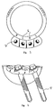
- the acetabular component of the present invention comprises a cup 1 which has a convex outer surface 2 and a rim 3.
- a pair of flanges 4 extends form the outer surface 2 at a point adjacent to the rim 3 at an angle ⁇ to the plane p1 of the rim 3.
- ⁇ is in the region of 20°.
- Lugs 5 may be present to prevent rotation and to facilitate the attachment of the cup to a gripping tool used during implantation.
- An example of a suitable tool can be found in GB2323036.
- each flange 4a and 4b is placed at an angle ⁇ to the plane p2 which passes through the apex of each flange.
- ⁇ is 20°.
- the two flanges making up each pair are at an opposite orientation and corresponding flanges from each pair are parallel.
- the two flanges 4a are parallel as are the two flanges 4b.
- Flanges 4a and 4b together make up a zigzag arrangement.
- the flanges may be labeled to indicate whether they are for use when the cup is being applied to the left or right side of the pelvis. As illustrated in Figure 3, the labeling 6 may be "L” and “R” for the left and right side respectively.
- the apertures in the flanges 7 are threaded so that screws 8 may be used as the fastening means.
- the use of corresponding parallel flanges for each side means that the screws 8 are held parallel at the optimum angle such that in use the screws are directed such that they enter the thickest part of the bone and act as struts.
- a hook 9 as shown in Figure 5 can be included to hook around the pelvis at a point adjacent to the obturator foramen at a point diametrically opposite to the flanges.
- the external surface of the cup may include surface structures 10 to promote bone growth.
- Figure 7 illustrates the use of the cup of the present invention in the pelvis.
- FIG 8 shows the preferred fastening means of the present invention.
- the fastening means is a screw 20 having a threaded shaft 21 and a tapered end 22.
- the screw thread is also tapered 23.
- Flutes 24 are provided in the tapered end 22. These flutes are generally deeper than is conventionally used.
- the head of the screw 25 may be of a cross configuration as illustrated in Figure 9.
- the arms of the cross generally have rounded edges.
- the acetabular component prosthesis of the present invention can be used with any arrangement of femoral component including those which could be described as a full femoral prosthesis component but also those used in resurfacing and in thrust plate technology.
- the component of the present invention may also be used with an natural femur head.
Landscapes
- Health & Medical Sciences (AREA)
- Orthopedic Medicine & Surgery (AREA)
- Life Sciences & Earth Sciences (AREA)
- Surgery (AREA)
- Animal Behavior & Ethology (AREA)
- General Health & Medical Sciences (AREA)
- Biomedical Technology (AREA)
- Heart & Thoracic Surgery (AREA)
- Engineering & Computer Science (AREA)
- Veterinary Medicine (AREA)
- Public Health (AREA)
- Medical Informatics (AREA)
- Neurology (AREA)
- Nuclear Medicine, Radiotherapy & Molecular Imaging (AREA)
- Molecular Biology (AREA)
- Oral & Maxillofacial Surgery (AREA)
- Transplantation (AREA)
- Cardiology (AREA)
- Vascular Medicine (AREA)
- Prostheses (AREA)
- Materials For Medical Uses (AREA)
Abstract
Description
An alternative arrangement is described in WO99/22672. Here in addition to the cup of the acetabular component being held in place by means of screws which are passed through the wall of the cup, an extension through which screws may be placed is provided to enable the cup to be fitted in deficient acetabulae. The extension may be provided at selected angles depending on the acetabular defect which is to be treated. Alternative arrangements are described in WO03/013397 and US2003/0171818.
Some, or substantially all, of the external surface of the cup may be formed as a porous surface or in an alternative arrangement may be provided with a bone promotion layer, such as a layer of hydroxyapatite, so as to facilitate and promote bone ingrowth into the outer portion of the cup.
- Figure 1
- is a side elevation of an acetabular component according to the present invention;
- Figure 2
- is an end elevation showing the flange end-on;
- Figure 3
- is a view from above;
- Figure 4
- is a view showing the cup with screws;
- Figure 5
- is a view from one side and above showing the presence of the hook;
- Figure 6
- is a side view of an embodiment without the hook with an exploded view illustrating the surface of the cup;
- Figure 7
- illustrates the acetabular component of the present invention in use;
- Figure 8
- illustrates a side view of a preferred fastening means; and
- Figure 9
- is a view of the fastening means of Figure 8 from above.
Claims (20)
- An acetabular component prosthesis adapted for affixation in a recess in a pelvis, compising:a cup shell having a generally convex outer surface adapted to be in contact with the bone in use, a generally concave inner surface and a rim;at least one pair of substantially adjacent flanges extending from the outer surface of the cup at a point proximal to the rim of the cup and angled at angle downwardly thereto;one flange of the pair being at an equal but opposite angle α to a plane extending across the apex of each of the flanges to the other of the pair; andat least one aperture in each of the pair of flanges through which in use fixation means may be passed to fix the cup into the recess in the pelvis.
- An acetabular component prosthesis according to Claim 1 wherein two pairs of flanges are present.
- An acetabular component prosthesis according to Claim 2 wherein corresponding flanges in each pair are positioned such that they are parallel.
- An acetabular component prosthesis according to any one of Claims 1 to 3 wherein each pair of flanges are contiguous.
- An acetabular component prosthesis according to any one of Claim 2 wherein the two pairs of flanges are contiguous.
- An acetabular component prosthesis according to any one of Claims 1 to 5 wherein is from about 0° to about 30°.
- An acetabular component prosthesis according to any one of Claims 1 to 6 wherein is from about 15° to about 25°.
- An acetabular component prosthesis according to Claim 6 or 7 wherein 8 is 20°.
- An acetabular component prosthesis according to any one of Claims 1 to 8 wherein α is from 10° to about 40° from a plane passing across the apex of the flanges.
- An acetabular component prosthesis according to Claim 9 wherein α is 20°.
- An acetabular component prosthesis according to any one of Claims 1 to 10 wherein the apertures in the flanges are threaded.
- An acetabular component prosthesis according to any one of Claims 1 to 11 wherein the acetabular component prosthesis additionally includes a hook extending from the external surface of the cup.
- An acetabular component prosthesis according to Claim 12 wherein the hook is located diametrically opposite the at least one pair of flanges.
- An acetabular component prosthesis according to any one of Claims 1 to 13 wherein each of the pair of flanges includes markings to enable the user to readily identify through which flange fastening means are for the right or left.
- An acetabular component prosthesis according to Claim 14 wherein the markings are "R" and "L".
- Fastening means comprising a screw having a threaded shaft and a tapered end which has a tapered screw thread.
- Fastening means according to Claim 16 wherein flutes are provided in the tapered end.
- Fastening means according to Claim 16 or 17 wherein the head of the screw is of a cross configuration.
- A kit of parts comprising an acetabular component prosthesis of any one of Claims 1 to 15 and at least one fastening means.
- A kit according to Claim 19 wherein the fastening means is the fastening means of any one of Claims 16 to 18.
Applications Claiming Priority (2)
| Application Number | Priority Date | Filing Date | Title |
|---|---|---|---|
| GB0408791 | 2004-04-20 | ||
| GBGB0408791.2A GB0408791D0 (en) | 2004-04-20 | 2004-04-20 | Prosthesis |
Publications (3)
| Publication Number | Publication Date |
|---|---|
| EP1588677A2 true EP1588677A2 (en) | 2005-10-26 |
| EP1588677A3 EP1588677A3 (en) | 2005-12-07 |
| EP1588677B1 EP1588677B1 (en) | 2008-05-28 |
Family
ID=32344074
Family Applications (1)
| Application Number | Title | Priority Date | Filing Date |
|---|---|---|---|
| EP05252456A Expired - Lifetime EP1588677B1 (en) | 2004-04-20 | 2005-04-20 | Acetabular prosthesis |
Country Status (4)
| Country | Link |
|---|---|
| EP (1) | EP1588677B1 (en) |
| AT (1) | ATE396670T1 (en) |
| DE (1) | DE602005007098D1 (en) |
| GB (1) | GB0408791D0 (en) |
Cited By (5)
| Publication number | Priority date | Publication date | Assignee | Title |
|---|---|---|---|---|
| WO2009115196A1 (en) * | 2008-03-18 | 2009-09-24 | Depuy (Ireland) | A cup component of an orthopaedic joint prosthesis |
| WO2010123677A3 (en) * | 2009-04-20 | 2011-03-24 | Michael Ries | Acetabular cup |
| EP1802255B1 (en) * | 2004-09-15 | 2014-12-03 | Wright Medical Technologies, Inc. | Unitary acetabular cup prosthesis with extension for deficient acetabulum |
| CN112773575A (en) * | 2021-01-22 | 2021-05-11 | 曾祥一 | Individualized reverse-folding embedded artificial acetabulum and manufacturing method |
| EP3606474B1 (en) | 2017-05-09 | 2023-06-21 | MatOrtho Limited | Ceramic acetabular cup |
Family Cites Families (2)
| Publication number | Priority date | Publication date | Assignee | Title |
|---|---|---|---|---|
| FR2633823A1 (en) * | 1988-07-07 | 1990-01-12 | Osteal Medical Laboratoires | Bone cotyle support ring for hip prosthesis |
| FR2798841B1 (en) * | 1999-09-28 | 2002-03-01 | Depuy France | ACETABULAR IMPLANT FOR HIP PROSTHESIS |
-
2004
- 2004-04-20 GB GBGB0408791.2A patent/GB0408791D0/en not_active Ceased
-
2005
- 2005-04-20 EP EP05252456A patent/EP1588677B1/en not_active Expired - Lifetime
- 2005-04-20 AT AT05252456T patent/ATE396670T1/en not_active IP Right Cessation
- 2005-04-20 DE DE602005007098T patent/DE602005007098D1/en not_active Expired - Lifetime
Cited By (8)
| Publication number | Priority date | Publication date | Assignee | Title |
|---|---|---|---|---|
| EP1802255B1 (en) * | 2004-09-15 | 2014-12-03 | Wright Medical Technologies, Inc. | Unitary acetabular cup prosthesis with extension for deficient acetabulum |
| WO2009115196A1 (en) * | 2008-03-18 | 2009-09-24 | Depuy (Ireland) | A cup component of an orthopaedic joint prosthesis |
| US8409294B2 (en) | 2008-03-18 | 2013-04-02 | Depuy (Ireland) | Cup component of an orthopaedic joint prosthesis |
| WO2010123677A3 (en) * | 2009-04-20 | 2011-03-24 | Michael Ries | Acetabular cup |
| CN102438554A (en) * | 2009-04-20 | 2012-05-02 | 迈克尔·里斯 | Acetabular cup |
| CN102438554B (en) * | 2009-04-20 | 2015-10-07 | 迈克尔·里斯 | acetabular cup |
| EP3606474B1 (en) | 2017-05-09 | 2023-06-21 | MatOrtho Limited | Ceramic acetabular cup |
| CN112773575A (en) * | 2021-01-22 | 2021-05-11 | 曾祥一 | Individualized reverse-folding embedded artificial acetabulum and manufacturing method |
Also Published As
| Publication number | Publication date |
|---|---|
| EP1588677B1 (en) | 2008-05-28 |
| ATE396670T1 (en) | 2008-06-15 |
| GB0408791D0 (en) | 2004-05-26 |
| EP1588677A3 (en) | 2005-12-07 |
| DE602005007098D1 (en) | 2008-07-10 |
Similar Documents
| Publication | Publication Date | Title |
|---|---|---|
| US7485148B2 (en) | Prosthesis | |
| EP1138283B1 (en) | Femoral hip prosthesis | |
| CA2267246C (en) | Acetabular ring prosthesis with reinforcement buttress | |
| JP4295987B2 (en) | Implant locking system | |
| US7621915B2 (en) | Acetabular reamer | |
| CN104220029B (en) | There is the reverse shoulder orthopaedic implants of ellipsoid joint broad-mouthed receptacle for holding liquid convex supporting head parts | |
| US6626948B2 (en) | Femoral hip prosthesis | |
| US7918896B2 (en) | Unitary acetabular cup prosthesis with extension for deficient acetabulum | |
| AU2010337239B2 (en) | Humeral head resurfacing implant | |
| US9192478B2 (en) | Revision hip implants and prosthesis systems | |
| CA2598027C (en) | Long sleeves for use with stems | |
| US6488716B1 (en) | Anatomic femoral prosthesis for total hip arthroplasty | |
| US20040064187A1 (en) | Humeral shoulder prosthesis | |
| US20080004711A1 (en) | An external proximal femoral prosthesis for total hip arthroplasty | |
| US10603178B2 (en) | Prosthetic hip system | |
| EP1588677B1 (en) | Acetabular prosthesis | |
| CN104203162B (en) | There is the reverse shoulder orthopaedic implants of the glenoid cavity installing plate parts of band screw locking top cover |
Legal Events
| Date | Code | Title | Description |
|---|---|---|---|
| PUAI | Public reference made under article 153(3) epc to a published international application that has entered the european phase |
Free format text: ORIGINAL CODE: 0009012 |
|
| PUAL | Search report despatched |
Free format text: ORIGINAL CODE: 0009013 |
|
| AK | Designated contracting states |
Kind code of ref document: A2 Designated state(s): AT BE BG CH CY CZ DE DK EE ES FI FR GB GR HU IE IS IT LI LT LU MC NL PL PT RO SE SI SK TR |
|
| AX | Request for extension of the european patent |
Extension state: AL BA HR LV MK YU |
|
| AK | Designated contracting states |
Kind code of ref document: A3 Designated state(s): AT BE BG CH CY CZ DE DK EE ES FI FR GB GR HU IE IS IT LI LT LU MC NL PL PT RO SE SI SK TR |
|
| AX | Request for extension of the european patent |
Extension state: AL BA HR LV MK YU |
|
| 17P | Request for examination filed |
Effective date: 20060602 |
|
| 17Q | First examination report despatched |
Effective date: 20060718 |
|
| AKX | Designation fees paid |
Designated state(s): AT BE BG CH CY CZ DE DK EE ES FI FR GB GR HU IE IS IT LI LT LU MC NL PL PT RO SE SI SK TR |
|
| 17Q | First examination report despatched |
Effective date: 20060718 |
|
| GRAP | Despatch of communication of intention to grant a patent |
Free format text: ORIGINAL CODE: EPIDOSNIGR1 |
|
| GRAS | Grant fee paid |
Free format text: ORIGINAL CODE: EPIDOSNIGR3 |
|
| GRAA | (expected) grant |
Free format text: ORIGINAL CODE: 0009210 |
|
| AK | Designated contracting states |
Kind code of ref document: B1 Designated state(s): AT BE BG CH CY CZ DE DK EE ES FI FR GB GR HU IE IS IT LI LT LU MC NL PL PT RO SE SI SK TR |
|
| REG | Reference to a national code |
Ref country code: GB Ref legal event code: FG4D |
|
| REG | Reference to a national code |
Ref country code: CH Ref legal event code: EP Ref country code: CH Ref legal event code: NV Representative=s name: WILLIAM BLANC & CIE CONSEILS EN PROPRIETE INDUSTRI |
|
| REF | Corresponds to: |
Ref document number: 602005007098 Country of ref document: DE Date of ref document: 20080710 Kind code of ref document: P |
|
| REG | Reference to a national code |
Ref country code: IE Ref legal event code: FG4D |
|
| PG25 | Lapsed in a contracting state [announced via postgrant information from national office to epo] |
Ref country code: SI Free format text: LAPSE BECAUSE OF FAILURE TO SUBMIT A TRANSLATION OF THE DESCRIPTION OR TO PAY THE FEE WITHIN THE PRESCRIBED TIME-LIMIT Effective date: 20080528 |
|
| PG25 | Lapsed in a contracting state [announced via postgrant information from national office to epo] |
Ref country code: FI Free format text: LAPSE BECAUSE OF FAILURE TO SUBMIT A TRANSLATION OF THE DESCRIPTION OR TO PAY THE FEE WITHIN THE PRESCRIBED TIME-LIMIT Effective date: 20080528 Ref country code: ES Free format text: LAPSE BECAUSE OF FAILURE TO SUBMIT A TRANSLATION OF THE DESCRIPTION OR TO PAY THE FEE WITHIN THE PRESCRIBED TIME-LIMIT Effective date: 20080908 |
|
| PG25 | Lapsed in a contracting state [announced via postgrant information from national office to epo] |
Ref country code: AT Free format text: LAPSE BECAUSE OF FAILURE TO SUBMIT A TRANSLATION OF THE DESCRIPTION OR TO PAY THE FEE WITHIN THE PRESCRIBED TIME-LIMIT Effective date: 20080528 Ref country code: NL Free format text: LAPSE BECAUSE OF FAILURE TO SUBMIT A TRANSLATION OF THE DESCRIPTION OR TO PAY THE FEE WITHIN THE PRESCRIBED TIME-LIMIT Effective date: 20080528 |
|
| NLV1 | Nl: lapsed or annulled due to failure to fulfill the requirements of art. 29p and 29m of the patents act | ||
| PG25 | Lapsed in a contracting state [announced via postgrant information from national office to epo] |
Ref country code: IS Free format text: LAPSE BECAUSE OF FAILURE TO SUBMIT A TRANSLATION OF THE DESCRIPTION OR TO PAY THE FEE WITHIN THE PRESCRIBED TIME-LIMIT Effective date: 20080928 |
|
| PG25 | Lapsed in a contracting state [announced via postgrant information from national office to epo] |
Ref country code: CZ Free format text: LAPSE BECAUSE OF FAILURE TO SUBMIT A TRANSLATION OF THE DESCRIPTION OR TO PAY THE FEE WITHIN THE PRESCRIBED TIME-LIMIT Effective date: 20080528 Ref country code: DK Free format text: LAPSE BECAUSE OF FAILURE TO SUBMIT A TRANSLATION OF THE DESCRIPTION OR TO PAY THE FEE WITHIN THE PRESCRIBED TIME-LIMIT Effective date: 20080528 Ref country code: SE Free format text: LAPSE BECAUSE OF FAILURE TO SUBMIT A TRANSLATION OF THE DESCRIPTION OR TO PAY THE FEE WITHIN THE PRESCRIBED TIME-LIMIT Effective date: 20080828 Ref country code: LT Free format text: LAPSE BECAUSE OF FAILURE TO SUBMIT A TRANSLATION OF THE DESCRIPTION OR TO PAY THE FEE WITHIN THE PRESCRIBED TIME-LIMIT Effective date: 20080528 |
|
| PG25 | Lapsed in a contracting state [announced via postgrant information from national office to epo] |
Ref country code: RO Free format text: LAPSE BECAUSE OF FAILURE TO SUBMIT A TRANSLATION OF THE DESCRIPTION OR TO PAY THE FEE WITHIN THE PRESCRIBED TIME-LIMIT Effective date: 20080528 Ref country code: BE Free format text: LAPSE BECAUSE OF FAILURE TO SUBMIT A TRANSLATION OF THE DESCRIPTION OR TO PAY THE FEE WITHIN THE PRESCRIBED TIME-LIMIT Effective date: 20080528 Ref country code: PT Free format text: LAPSE BECAUSE OF FAILURE TO SUBMIT A TRANSLATION OF THE DESCRIPTION OR TO PAY THE FEE WITHIN THE PRESCRIBED TIME-LIMIT Effective date: 20081028 Ref country code: SK Free format text: LAPSE BECAUSE OF FAILURE TO SUBMIT A TRANSLATION OF THE DESCRIPTION OR TO PAY THE FEE WITHIN THE PRESCRIBED TIME-LIMIT Effective date: 20080528 |
|
| PLBE | No opposition filed within time limit |
Free format text: ORIGINAL CODE: 0009261 |
|
| STAA | Information on the status of an ep patent application or granted ep patent |
Free format text: STATUS: NO OPPOSITION FILED WITHIN TIME LIMIT |
|
| PG25 | Lapsed in a contracting state [announced via postgrant information from national office to epo] |
Ref country code: BG Free format text: LAPSE BECAUSE OF FAILURE TO SUBMIT A TRANSLATION OF THE DESCRIPTION OR TO PAY THE FEE WITHIN THE PRESCRIBED TIME-LIMIT Effective date: 20080828 Ref country code: EE Free format text: LAPSE BECAUSE OF FAILURE TO SUBMIT A TRANSLATION OF THE DESCRIPTION OR TO PAY THE FEE WITHIN THE PRESCRIBED TIME-LIMIT Effective date: 20080528 |
|
| 26N | No opposition filed |
Effective date: 20090303 |
|
| PG25 | Lapsed in a contracting state [announced via postgrant information from national office to epo] |
Ref country code: IT Free format text: LAPSE BECAUSE OF FAILURE TO SUBMIT A TRANSLATION OF THE DESCRIPTION OR TO PAY THE FEE WITHIN THE PRESCRIBED TIME-LIMIT Effective date: 20080528 |
|
| PG25 | Lapsed in a contracting state [announced via postgrant information from national office to epo] |
Ref country code: MC Free format text: LAPSE BECAUSE OF NON-PAYMENT OF DUE FEES Effective date: 20090430 |
|
| PG25 | Lapsed in a contracting state [announced via postgrant information from national office to epo] |
Ref country code: PL Free format text: LAPSE BECAUSE OF FAILURE TO SUBMIT A TRANSLATION OF THE DESCRIPTION OR TO PAY THE FEE WITHIN THE PRESCRIBED TIME-LIMIT Effective date: 20080528 |
|
| REG | Reference to a national code |
Ref country code: CH Ref legal event code: PFA Owner name: FINSBURY (DEVELOPMENT) LIMITED Free format text: FINSBURY (DEVELOPMENT) LIMITED#13 MOLE BUSINESS PARK, RANDALLS ROAD#LEATHERHEAD, SURREY KT22 0BA (GB) -TRANSFER TO- FINSBURY (DEVELOPMENT) LIMITED#13 MOLE BUSINESS PARK, RANDALLS ROAD#LEATHERHEAD, SURREY KT22 0BA (GB) |
|
| PG25 | Lapsed in a contracting state [announced via postgrant information from national office to epo] |
Ref country code: GR Free format text: LAPSE BECAUSE OF FAILURE TO SUBMIT A TRANSLATION OF THE DESCRIPTION OR TO PAY THE FEE WITHIN THE PRESCRIBED TIME-LIMIT Effective date: 20080829 |
|
| PG25 | Lapsed in a contracting state [announced via postgrant information from national office to epo] |
Ref country code: LU Free format text: LAPSE BECAUSE OF NON-PAYMENT OF DUE FEES Effective date: 20090420 |
|
| PG25 | Lapsed in a contracting state [announced via postgrant information from national office to epo] |
Ref country code: HU Free format text: LAPSE BECAUSE OF FAILURE TO SUBMIT A TRANSLATION OF THE DESCRIPTION OR TO PAY THE FEE WITHIN THE PRESCRIBED TIME-LIMIT Effective date: 20081129 |
|
| REG | Reference to a national code |
Ref country code: CH Ref legal event code: PCAR Free format text: NOVAGRAAF SWITZERLAND SA;CHEMIN DE L'ECHO 3;1213 ONEX (CH) |
|
| PG25 | Lapsed in a contracting state [announced via postgrant information from national office to epo] |
Ref country code: TR Free format text: LAPSE BECAUSE OF FAILURE TO SUBMIT A TRANSLATION OF THE DESCRIPTION OR TO PAY THE FEE WITHIN THE PRESCRIBED TIME-LIMIT Effective date: 20080528 |
|
| PG25 | Lapsed in a contracting state [announced via postgrant information from national office to epo] |
Ref country code: CY Free format text: LAPSE BECAUSE OF FAILURE TO SUBMIT A TRANSLATION OF THE DESCRIPTION OR TO PAY THE FEE WITHIN THE PRESCRIBED TIME-LIMIT Effective date: 20080528 |
|
| REG | Reference to a national code |
Ref country code: FR Ref legal event code: PLFP Year of fee payment: 11 |
|
| REG | Reference to a national code |
Ref country code: FR Ref legal event code: PLFP Year of fee payment: 12 |
|
| REG | Reference to a national code |
Ref country code: FR Ref legal event code: PLFP Year of fee payment: 13 |
|
| REG | Reference to a national code |
Ref country code: FR Ref legal event code: PLFP Year of fee payment: 14 |
|
| PGFP | Annual fee paid to national office [announced via postgrant information from national office to epo] |
Ref country code: IE Payment date: 20240312 Year of fee payment: 20 |
|
| PGFP | Annual fee paid to national office [announced via postgrant information from national office to epo] |
Ref country code: GB Payment date: 20240229 Year of fee payment: 20 |
|
| PGFP | Annual fee paid to national office [announced via postgrant information from national office to epo] |
Ref country code: FR Payment date: 20240311 Year of fee payment: 20 |
|
| PGFP | Annual fee paid to national office [announced via postgrant information from national office to epo] |
Ref country code: DE Payment date: 20240306 Year of fee payment: 20 |
|
| PGFP | Annual fee paid to national office [announced via postgrant information from national office to epo] |
Ref country code: CH Payment date: 20240501 Year of fee payment: 20 |
|
| REG | Reference to a national code |
Ref country code: DE Ref legal event code: R071 Ref document number: 602005007098 Country of ref document: DE |
|
| REG | Reference to a national code |
Ref country code: CH Ref legal event code: PL |
|
| REG | Reference to a national code |
Ref country code: GB Ref legal event code: PE20 Expiry date: 20250419 |
|
| REG | Reference to a national code |
Ref country code: IE Ref legal event code: MK9A |
|
| PG25 | Lapsed in a contracting state [announced via postgrant information from national office to epo] |
Ref country code: GB Free format text: LAPSE BECAUSE OF EXPIRATION OF PROTECTION Effective date: 20250419 |
|
| PG25 | Lapsed in a contracting state [announced via postgrant information from national office to epo] |
Ref country code: IE Free format text: LAPSE BECAUSE OF EXPIRATION OF PROTECTION Effective date: 20250420 |