EP1588604B1 - Rundballenpresse - Google Patents
Rundballenpresse Download PDFInfo
- Publication number
- EP1588604B1 EP1588604B1 EP04101713A EP04101713A EP1588604B1 EP 1588604 B1 EP1588604 B1 EP 1588604B1 EP 04101713 A EP04101713 A EP 04101713A EP 04101713 A EP04101713 A EP 04101713A EP 1588604 B1 EP1588604 B1 EP 1588604B1
- Authority
- EP
- European Patent Office
- Prior art keywords
- round baler
- rolls
- pivot
- bale
- roll
- Prior art date
- Legal status (The legal status is an assumption and is not a legal conclusion. Google has not performed a legal analysis and makes no representation as to the accuracy of the status listed.)
- Expired - Lifetime
Links
- 230000015572 biosynthetic process Effects 0.000 claims description 7
- 238000000034 method Methods 0.000 claims description 4
- 230000007246 mechanism Effects 0.000 description 10
- 238000004904 shortening Methods 0.000 description 2
- 238000010276 construction Methods 0.000 description 1
- 230000007423 decrease Effects 0.000 description 1
- 238000006073 displacement reaction Methods 0.000 description 1
- 230000005484 gravity Effects 0.000 description 1
- 239000000725 suspension Substances 0.000 description 1
- 230000001360 synchronised effect Effects 0.000 description 1
- 230000007723 transport mechanism Effects 0.000 description 1
Images


Classifications
-
- A—HUMAN NECESSITIES
- A01—AGRICULTURE; FORESTRY; ANIMAL HUSBANDRY; HUNTING; TRAPPING; FISHING
- A01F—PROCESSING OF HARVESTED PRODUCE; HAY OR STRAW PRESSES; DEVICES FOR STORING AGRICULTURAL OR HORTICULTURAL PRODUCE
- A01F15/00—Baling presses for straw, hay or the like
- A01F15/08—Details
- A01F15/0825—Regulating or controlling density or shape of the bale
- A01F15/0833—Regulating or controlling density or shape of the bale for round balers
-
- A—HUMAN NECESSITIES
- A01—AGRICULTURE; FORESTRY; ANIMAL HUSBANDRY; HUNTING; TRAPPING; FISHING
- A01F—PROCESSING OF HARVESTED PRODUCE; HAY OR STRAW PRESSES; DEVICES FOR STORING AGRICULTURAL OR HORTICULTURAL PRODUCE
- A01F15/00—Baling presses for straw, hay or the like
- A01F15/07—Rotobalers, i.e. machines for forming cylindrical bales by winding and pressing
- A01F2015/077—Pressing chamber formed by belts and rollers
-
- A—HUMAN NECESSITIES
- A01—AGRICULTURE; FORESTRY; ANIMAL HUSBANDRY; HUNTING; TRAPPING; FISHING
- A01F—PROCESSING OF HARVESTED PRODUCE; HAY OR STRAW PRESSES; DEVICES FOR STORING AGRICULTURAL OR HORTICULTURAL PRODUCE
- A01F15/00—Baling presses for straw, hay or the like
- A01F15/07—Rotobalers, i.e. machines for forming cylindrical bales by winding and pressing
- A01F2015/0795—Pressing chamber with variable volume
Definitions
- This invention relates to a round baler having side structures, fixed rolls, at least two moveable pivot arms carrying mobile rolls, and flexible baling means creating one endless circle and routed over said rolls to encompass a bale chamber.
- European Patent specification EP 309 936 B1 discloses a round baler with a single set of endless belts, which are routed over a series of fixed and mobile rolls, whereas the mobile rolls are carried on two tensioning arm, which create several loops to provide sufficient bale length to extend over the circumference of a completed bale.
- a lower tensioning arm is applied by a spring, which extends with additional crop entering the bale chamber.
- EP A1 309 941 discloses a round baler with two sets of endless belts and two tensioning arms, which are controlled by means of a single hydraulic cylinder. This hydraulic cylinder is used to control the tension in the two sets of belts to provide for controlled movement of the bale during formation and unloading.
- EP A1 1 308 078 discloses a round baler with side structures and mobile and fixed rolls.
- a single tension arm is provided in about the center of the bale chamber to create a loop taking up the slack in the belts, when the bale chamber is empty.
- Another loop is formed by an unloading pivot frame, when it is moved to an unloading position.
- EP A1 1 308 079 teaches a round baler with side structures and mobile and fixed rolls.
- a single tension arm is provided in the front area of the round baler to release more or less of a loop of the belts to the circumference of a growing bale.
- a tensioning roll acts onto the belts.
- the tensioning arm is provided with a pair of parallel rolls, which guide two strands of the belts and limit the bale chamber in its upper region.
- Another loop is formed by an unloading pivot frame, when it is moved to an unloading position.
- a round baler with two pivot arms both being journalled on fixed sidewalls of a bale chamber, which can be opened by raising rear moveable sidewalls to unload a bale. Due to the weight of the rear sidewalls - the so-called gate - and its size, unloading a bale takes considerable time.
- EP 1 308 079 A1 teaches a round baler with an unloading pivot frame operating outside a bale chamber and being equipped with one tensioning arm only. It has been found that this arrangement does not allow to create bales with are large diameter.
- the pivot arm does neither extend much over the boundary of the round baler, when being in a respective end position and does thus not hit an obstacle or move the center of gravity to an unwanted direction; nor will it occupy space in the front part of the round baler, which is needed to install a net wrapping and/or or tying device.
- the baling means may be a set of baling means like flexible belts or a chain and slat assembly or a single belt.
- an unloading pivot frame When an unloading pivot frame is used to release the bale from the bale chamber, it can at the same time, i.e. when the baling means get lose, form a loop to take out the slack from the baling means.
- a loop or such loops may be generated by one roll hitting a strand between two other rolls.
- Said roll may be a fixed roll or it may be one on the unloading pivot frame hitting a span between a fixed and a fixed or mobile roll.
- a linear actuator commonly called a hydraulic cylinder
- Hydraulic and electric drives are easy to control and available on round balers driven by a tractor or the like.
- a common control for the two or more pivot arms as opposed to a spring or another control the costs are kept lower as by using more of them.
- pairs of two may be connected and controlled by a common link, cable, or the like.
- the actuator may be driven hydraulically or electrically and may join the pivot arms directly or via links, cables, chains, or the like.
- Resistance in the bale forming means against which the actuator is extended or retracted will result in tension in the baling means and this will create a dense bale.
- Such resistance may be variable during the baling process to provide a dense bale throughout its diameter or a soft core at the beginning and a dense bale later on.
- lever arms By using lever arms to connect the actuator to the pivot arms, it is possible to select their position with respect to the pivot arm such, that the momentum can be transferred best. Another advantage is seen in the possibility to control the sense of rotation of the pivot arms, which allows to adjust to given structural restrictions, like rolls or struts crossing the path of the pivot arms.
- pivot arm When either pivot arm can move through the bale chamber, it can assist the bale movement during unloading or at least avoid, that the bale rolls back.
- Having three mobile rolls on a pivot arm enables to create more loops and/or to control the size of the bale chamber by releasing more or less baling means length.
- baling means strands running over rolls at said ends will neither be damaged nor create friction.
- a second pivot arm having legs being located outside the bale chamber may pivot in a bigger region, since no fixed rolls or mobile rolls in the bale chamber will cross their path.
- the actuator In a case, in which the actuator is arranged such, that it is not fully retracted, when the bale formation process starts, it may release baling means length in a first movement and may take slack out of the baling means in a second movement.
- pivot arms When the pivot arms rotate in the same or opposite directions during bale formation or subsequent to it, they may avoid running into each other, they may make best use of a common actuator, etc.
- baling means In a round baler, in which an unloading pivot frame is provided with three mobile rolls, whereas the baling means is routed between them, the baling means and thus the bale chamber can easily be controlled and another loop can be created.
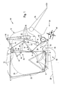
- FIG. 1 shows a round baler 10 having a chassis 12, a first pivot arm 14, a second pivot arm 16, fixed rolls 18, mobile rolls 20, baling means 22, a baling means control 24, a feeding mechanism 26 and an unloading mechanism 28.
- This round baler 10 is of the variable chamber type and is pulled behind a tractor or the like (not shown) over a field to pick-up crop and to form round cylindrical bales 38 thereof, as this is known in general. Although it is not shown, this round baler 10 may comprise a twine, net or plastic wrapping system, known as well. Furthermore the round baler 10 may be part of a self-propelled vehicle or be of the pull type.
- the chassis 12 substantially has a wheeled axle 30, side structures 32, to which walls 33 are attached, and a tongue 34.
- the wheeled axle 30 may be of the single rigid axle type as shown, or e.g. of the tandem axle type with or without spring suspension.
- Each side structure 32 is oriented vertically, carried by the wheeled axle 30 and forms the round baler 10 with its unshown walls laterally.
- Such side structure 32 and independent walls are disclosed in more detail in EP 1 264 531 , to which this refers, but this invention is not limited to a use with such design. In this case the side structures 32 are not split in the area of a bale chamber 36 formed between them.
- the side structures 32 stay in place, when a formed bale 38 is ejected, as opposed to side walls in the prior art, of which a rear portion is lifted during unloading the bale 38. While in general the walls 33 could be an integral part of the side structures 32, they are shown is dashed lines in the following embodiments as parts, which are attached to the side structures 32 and assume as the only function to cover the bale chamber 36 laterally. Unlike in the prior art they are not split in halves and do not or hardly extend beyond the silhouette of a completed bale 38. If such separate walls 33 are present, the pivot arms 14 and 16 and the fixed rolls 18 are carried by other parts of the side structures 32.
- the tongue 34 is fixed to the side structures 32 as this is known, to connect the round baler 10 to the tractor (not shown).
- the distance between the side walls on the side structure 32 may be adjustable during operation.
- the first pivot arm 14 is located between the side structures 32 and assumes substantially the form of an "U".
- the base of the "U” of the first pivot arm 14 is journalled on an axis 40 oriented horizontally and transverse to the travel direction of the round baler 10 and being fixed with respect to the side structures 32.
- the axis 40 is located approximately one third of the side structure 32 length from the front and one third of the side wall or side structure 32 height from the top.
- Legs 42 of the "U" of the first pivot arm 14 extend parallel to the side structure 32 or its side walls and are pivotable in a vertical direction between a 7:00 (bale start position) and 11:00 (full bale position) o'clock pointer position, when viewed from the R.H. side, shown in the drawing.
- the length of the legs 42 reaches almost half of the height of the side structure 32, i.e. they terminate substantially close to a line between a fixed roll D and a mobile roll g, when an unloading pivot frame 54 is in its lower position.
- Rigidly connected to the legs 42 or to the base of the "U" is at least one lever arm 44.
- the second pivot arm 16 is of similar "U" construction as the first pivot arm 14, whereas an axis 45 for the end regions of legs 46 for the base of the "U” is located at about half way of the length of round baler 10 (without tongue) close to the roll D, i.e. in the upper region, but slightly below and behind of it.
- the legs 46 extend outside the bale chamber 36, i.e. they face the outer surfaces of the side walls and terminate approximately at the front upper corner of the round baler 10.
- lever arms 50 are fixed to the legs 46 and extend substantially perpendicular therefrom.
- the legs 46 are connected by the base of the "U".
- the legs 46 may pivot in a range between a 1:00 position (unloading the bale) over a 2:00 position (bale start position) and a 4:00 o'clock (full bale position) pointer position. They run parallel to the side structures 32 and are pivotable in a vertical direction.
- Fixed rolls 18 have end portions being rotatably journalled in, on or at the side structures 32, whereas they all run parallel to each other and parallel to the ground on which the round baler 10 stands.
- more or less fixed rolls 18 may be present, whereas most of them are of the same design, i.e. a roll body journalled on a shaft or stub shaft or a roll body with fixed stub shafts rotatably received in bearings (not shown) in side structures 32.
- the diameter of the rolls 18 may be different from roll 18 to roll 18. It is obvious that "fixed” means, that their position is fixed, whereas the rolls 18 as such can rotate.
- the fixed rolls 18 are designated by capital letters A to I, whereas:
- At least one of the rigid rolls 18 is driven and formed such that it may transfer movement energy from the driven roll 18 to the baling means 22. Some of the rolls 18 may have guide means for the baling means 22.
- the mobile rolls 20 are designated by small letters a to j, whereas:
- the unloading pivot frame 54 has substantially the form of a triangle, an upper corner (as seen in fig. 1) of which is journalled about an axis 56, parallel to the axes 40, 45 and close to the center of bale chamber 36, when being filled.
- the rear lower corner are of the unloading pivot frame 54 finds itself in the rear lower corner area of the side structures 32 and the front lower corner area of the unloading pivot frame 54 is located immediately behind a lower roll 64 to be described later - each when viewing figure 1.
- the baling means 22 in this embodiment is formed by a set of belts, running parallel to each other in laterally spaced relationship. Instead of, a single endless belt or a chain and slat conveyor could be used to provide for flexibility, allowing to run over the rolls 18 and 20.
- the routing of the baling means 22 is described in the following with respect to the embodiment and mode of operation shown in figure 1.
- the routing of the baling means 22 is: H - between H and G - G - e - between I and H - I - E - C - between h and i - g - j - between a and b - D - between a and b - A.
- a loop 70 is formed by means of the strand between rolls I and G, as the baling means 22 is routed over roll e.
- Another loop - no reference no. - is formed about roll D, whereas its size decreases with the growing bales and is determined by the position of the mobile rolls a and b.
- the baling control means 24 is composed of various not shown pump, sump, valves, sensors, lines, a CPU, etc. and for the pivot arms 14, 16 one actuator 58 extending between and pivotally fixed to lever arm 44 of the first pivot arm 14 and lever arm 50 of the second pivot arm 16. Said control means 24 receives and computes signals coming from the various round baler components as well as from an operator.
- the output signals of the CPU controlling the actuator 58 are such, that during bale formation a certain resistance acts onto the pivot arms 14 and/or 16 to provide for a wanted density in the bale 38 and that after unloading the bale 38, the pivot arms 14, 16 return to their initial bale starting position.
- the actuator 58 of this embodiment is in the form of a single or double acting linear hydraulic motor; alternatively it could be an electric motor. As shown in figures 1 to 3 and different from the subsequent embodiments, only this actuator 58 is used to control the position of the first and of the second pivot arm 14, 16. This is possible, since the forces applying both pivot arms 14, 16 are quite balanced.
- an actuator 58 in the form of a hydraulic cylinder attached directly to the pivot arms 14, 16 or their lever arms 44, 50 one could use a hydraulic cylinder for one direction and a spring for a movement in the other direction, one could use a strong spring only, like a coil spring, one could use an electric or pneumatic motor, one could apply the actuator - being in the form of a hydraulic cylinder, of a spring, or of a motor - via a cable or linkage to both pivot arms 14, 16 or directly to one of the pivot arms 14, 16 and via a cable or link to the other pivot arm 16, 14.
- the unloading pivot frame 54 is raised and if need be lowered by an unshown hydraulic actuator, which is controlled as well by these baling control means to achieve a synchronized movement.
- the feeding mechanism 26 is designed in the usual way, i.e. it includes a pick-up 60, downstream thereof a conveyor 62 formed as a cutting unit, a converging auger or other transport mechanism and in the area of the inlet 52 the bottom roll 64, which all together assist in taking crop from the ground and deliver it through the inlet 52 into the bale chamber 36, where it is rolled to a bale 38.
- the unloading mechanism 28 is formed as a ramp - remote controlled or spring loaded - on which the unloaded bale 38 rolls down onto the ground, as this is known.
- spans of the baling means 22 between a and j as well as between b and A form two sides of the bale chamber 36, which is kept minimal, since pivot arm 14 is in its lowest, 7:00 position.
- Roll j lies adjacent to bottom roll 64, since the unloading pivot frame 54 assumes its lowest position, which brings the span between rolls a and j into a vertical orientation.
- the actuator 58 assumes its minimal length and first pivot arms 14 assumes its lowest location, while second pivot arm is in the about 2:00 position.
- bale 38 When crop is fed continuously through the inlet 52 a bale 38 will start to grow and push pivot arm 14 upward thereby extracting actuator 58 against a force provided by resistance in the baling control means 24, for example created by a nozzle, a valve or the like. Simultaneously pivot arm 16 will be pulled downwardly by the baling means 22 shortening the span between rolls G and I, i.e. loop 70, in order to adjust to the growing circumference of the bale 38. Both pivot arms 14, 16 rotate clockwise. Movement of the pivot arms 14, 16 and thus also of the mobile rolls a, b and e continuous until the bale 38 has reached its desired or maximum size - see figure 2.
- the unloading pivot frame 54 is pivoted clockwise about axis 56 into the position shown in figure 3, in which a line through the center of rolls g and h shows an inclination to the ground of about 30 degrees. Due to the upward movement also roll i moved upwardly and hit the span between rolls g and C. Roll i creates a loop 66 (fig. 3) to take out slack in the baling means 22, which appears, as soon as the bale 38 rolls down the unloading mechanism 28. As soon as the bale 38 has left the bale chamber 36, the second pivot arm 16 moves upward in a counter clockwise direction, thereby enlarging the loop 70 to the biggest possible extent. Afterwards both pivot arms 14, 16 move down and finally the situation shown in figure 1 is reached again.
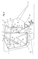
- Figures 4 to 6 show a second embodiment having many components in common with the first embodiment, especially one actuator 58 for two pivot arms 14, 16.
- round baler 10 and the design of its chassis 12 are the same or equivalent to that of the first embodiment.
- the first pivot arm 14 has the same design and is located and journalled in a similar or identical way. In particular it has lever arms 44, to which actuator 58 may be connected.
- the second pivot arm 16 is different from the one of the first embodiment in some respects.
- the second pivot arm 16 of the second embodiment is journalled on axis 45, which is located in the wider area of the rear upper corner of the side structures 32 and close to the roll C.
- the legs 46 extend inside the maximum shape of the bale chamber 36, and terminate slightly below the middle of the height of the side structure 32. When the bale chamber 36 is empty, as this is shown in figure 4, the legs 46 run substantially vertical, whereas the axis 45 is situated on top of the legs 46.
- lever arms 50 are fixed to the legs 46 and extend substantially perpendicular therefrom.
- the legs 46 are connected by the base of the "U".
- the legs 46 may pivot in a range between a 6:00 and a 2:00 o'clock pointer position.
- both pivot arms 14, 16 rotate in contrary direction, i.e. as viewed first pivot arm 14 clockwise and second pivot arm 16 counter clockwise, each when the bale 38 is growing.
- Fixed rolls 18 A, C and D are in the same or substantially the same position as those of the first embodiment. However fixed rolls B, F, J and K are added, which are located at different places. Rolls B and J are arranged very close to each other and between fixed rolls C and D, however slightly above a line extending through the centers of the rolls C and D and thus close to the upper edge of the side structure 32. Rolls F and K are arranged in the wider front upper corner area of the side structures 32. Rolls F and K are located very close to each other, whereas roll K is offset with respect to roll F to the rear and below of it. This roll K is provided to increase the amount of wrap around the drive roll F and to move the respective strand of the baling means 22 out of contact with the first pivot arm 14 between its legs 42.
- Second pivot arm 16 now bears two mobile rolls d and e at the end of it remote from axis 45, whereas mobile roll 20,d forms the end of the second pivot arm 16 and its direct linear extension, while roll e is situated radially inward from roll 20,d on the second pivot arm 16.
- Roll 20,e forms the idling roll 20, while roll 20,d is used to avoid interference as this will be described later.
- Rolls g, h, and i are present on the unloading pivot frame 54, not mobile roll j of the second embodiment; instead of mobile roll j, mobile roll g has a bigger diameter.
- the baling means 22 is equivalent to the one in the first embodiment.
- the baling control means 24 contains again one actuator 58 between the lever arms 44 and 50, whereas said actuator 58 is joined to these lever arms 44, 50 above the axes 40, 45, when the round baler 10 assumes the position shown in figure 4, i.e. when the bale chamber 36 is empty.
- a second actuator 72 is possibly provided, which at one end is fixed to the chassis 12 or the side structures 32 and which at its other end is connected to the arm 44, where the first actuator 58 applies to it. It should be understood for this as well as for the third embodiment, that one actuator 58 is meant at least one, whereas one may be provided on each side of the round baler 10. The same is true for the second actuator 72.
- the second actuator 72 - if present - is used to control their positions particularly to synchronize displacement of pivot arm 16 in relation to the bale position during its ejection and to take advantage of the pivot arm 16 position to positively push the bale 38 out. It is made clear hereby, that mostly the second actuator 72 is an option, rather than a must.
- the feeding mechanism 26, the unloading mechanism 28, the unloading pivot frame 54 and the bottom roll 64 are similar or identical to those of the first and the second embodiment.
- baling means 22 is: K - between K and F - F - J - between e and d - e - B - C - h - between h and i - g between a and b - D - between a and b - A.
- this routing another loop 74 is formed by means of the strand between rolls B and J, as the baling means 22 is routed over roll e.
- This loop 74 is used instead of a loop 70 about roll c in the first embodiment. Bale formation starts when the round baler 10 assumes the position as shown in fig. 4.
- the first actuator 58 is shortened to its minimum, the second actuator 72 - if present - is extended to its maximum.
- the bale chamber 36 has the smallest dimension and is substantially of triangular shape.
- bale 38 When crop is fed continuously through the inlet 52 a bale 38 will start to grow and push pivot arm 14 clockwise upwardly as viewed thereby extracting actuator 58 against a force provided by resistance in the baling control means 24, for example created by a nozzle, a valve or the like. Simultaneously pivot arm 16 will be pulled upwardly by the baling means 22, however counter clockwise, thereby shortening the loop 74 in order to adjust to the growing circumference of the bale 38. Movement of the pivot arms 14, 16 and thus also of the mobile rolls a, b, d and e continues until the bale 38 has reached its desired or maximum size - see figure 5.
- the unloading pivot frame 54 is pivoted clockwise about axis 56 into the position shown in figure 6, in which a line through the center of rolls g and h shows an inclination to the ground of about 30 degrees. Due to the upward movement also roll i moved upwardly and hit the span between rolls g and C. Roll i creates a loop 66 (fig. 6) to take out slack in the baling means 22, which appears, as soon as the bale 38 rolls down the unloading mechanism 28. As soon as the bale 38 has left the bale chamber 36, the second pivot arm 16 moves downward in a clockwise direction, thereby enlarging the loop 74 to the biggest possible extent and driving the bale 38 out. In this situation mobile roll d avoids that two strands of the baling means 22 gets in contact with each other. Afterwards or simultaneously actuator 72 extends again, first pivot arm 14 moves down and finally the situation shown in figure 4 is reached again.
- FIGS 7 and 8 show a third embodiment being different from the second embodiment insofar, as the unloading pivot frame 54 has mobile rolls h and g only and as a fixed roll L is added very close but slightly above and rearward of fixed roll C, whereas the baling means 22 is routed through the gap between the fixed rolls L and C. Furthermore the unloading pivot frame 54 is located outside the side structures 32.
- the remainder of the round baler 10 including the routing of the baling means 22 and the use of a first and a second actuator 58 and 72 is identical.
- the function during forming a bale 38 is identical to the function in the round baler 10 of the third embodiment.
- loop 76 is formed in the strand between the rolls h and B when said strand hits the fixed roll L. This loop 76 is created to take out slack in the baling means 22, which appears, as soon as the bale 38 rolls down the unloading mechanism 28. Loop 76 is used instead of loop 66 (fig. 8).
Landscapes
- Life Sciences & Earth Sciences (AREA)
- Environmental Sciences (AREA)
- Storage Of Harvested Produce (AREA)
- Toys (AREA)
- Finger-Pressure Massage (AREA)
- Food-Manufacturing Devices (AREA)
- Preliminary Treatment Of Fibers (AREA)
Claims (15)
- Rundballenpresse (10) mit Seitenstrukturen (32), ortsfesten Rollen (18), mindestens zwei beweglichen Schwenkarmen (14, 16), die bewegliche Rollen (20) tragen, und einem flexiblen Ballenpressmittel (22), das einen Endloskreis bildet und über die Rollen (18, 20) geführt ist, um eine Ballenkammer (36) zu umfassen, dadurch gekennzeichnet, dass:a) ein Schwenkarm (14) mindestens zwei Rollen (20,a,b) aufweist, um eine Schlaufe des Ballenpressmittels (22) dazwischen zu führen, wobei die Schlaufe an einer Seite über eine ortsfeste Rolle (18,D) läuft und sich an der anderen Seite zur Ballenkammer (36) öffnet,b) ein Schwenkarm (16) mindestens eine bewegliche Rolle (20,e) aufweist, die auf einen Trum des Ballenpressmittels (22) einwirkt, das sich zwischen zwei Rollen (18,G, 18,I oder 18,B, 18,J) erstreckt, von denen mindestens eine ortsfest ist, und zumindest teilweise mit der potentiellen Ballenkammer (36) zusammenfällt,c) ein Entladeschwenkrahmen (54) mit einer oder mehreren Rollen (20,h,g) versehen ist und mittels einer ortsfesten Rolle (18C, L) oder beweglichen Rolle (20 i) bei Bewegung in eine Entladeposition eine weitere Schlaufe im Ballenpressmittel (22) erzeugt.
- Rundballenpresse (10) nach Anspruch 1, dadurch gekennzeichnet, dass:a) eine ortsfeste Rolle (18,C) in oder neben dem Bereich vorgesehen ist, der von dem sich bewegenden Entladeschwenkarm (54) durchquert wird, undb) ein Trum des Ballenpressmittels (22) durch Bewegen des Entladeschwenkrahmens (54) an die ortsfeste Rolle (18,C) angelegt wird.
- Rundballenpresse (10) nach einem oder mehreren der vorhergehenden Ansprüche, gekennzeichnet durch mindestens ein Stellglied (58), das die Bewegung des ersten und/oder zweiten Schwenkarms (14, 16) steuert.
- Rundballenpresse (10) nach einem oder mehreren der vorhergehenden Ansprüche, dadurch gekennzeichnet, dass das Stellglied (58) als ein Linearmotor ausgebildet ist, der hydraulisch oder elektrisch angetrieben wird.
- Rundballenpresse (10) nach einem oder mehreren der vorhergehenden Ansprüche, dadurch gekennzeichnet, dass sich das Stellglied (58) gegen Widerstand bewegt, während die Ballenkammer (36) gefüllt wird.
- Rundballenpresse (10) nach einem oder mehreren der vorhergehenden Ansprüche, dadurch gekennzeichnet, dass das Stellglied (58) die Schwenkarme (14, 16) an Hebelarmen (44, 50) verbindet, die so angeordnet sein können, dass beide Schwenkarme (14, 16) eine Drehung in der gleichen oder in entgegengesetzter Richtung bereitstellen.
- Rundballenpresse (10) nach einem oder mehreren der vorhergehenden Ansprüche, dadurch gekennzeichnet, dass sich der zweite Schwenkarm (16) während des oder nach dem Entladen(s) eines Ballens (38) durch die Ballenkammer (36) bewegt.
- Rundballenpresse (10) nach einem oder mehreren der vorhergehenden Ansprüche, dadurch gekennzeichnet, dass ein zweites Stellglied (72) vorgesehen ist, das direkt oder indirekt auf das erste Stellglied (58) einwirkt.
- Rundballenpresse (10) nach einem oder mehreren der vorhergehenden Ansprüche, dadurch gekennzeichnet, dass der erste Schwenkarm (14) mit einer beweglichen Rolle versehen ist, um das Ballenpressmittel (22) freilaufen zu lassen, und mit zwei beweglichen Rollen (20,a, 20,b), um die Ballenkammer (36) in einem oberen Bereich zu schließen.
- Rundballenpresse (10) nach einem oder mehreren der vorhergehenden Ansprüche, dadurch gekennzeichnet, dass der zweite Schwenkarm (16) an seinen Enden mit beweglichen Rollen (20,d) versehen ist.
- Rundballenpresse (10) nach einem oder mehreren der vorhergehenden Ansprüche, dadurch gekennzeichnet, dass der zweite Arm (16) Schenkel (46) aufweist, die sich außerhalb der Ballenkammer (36) befinden.
- Rundballenpresse (10) nach einem oder mehreren der vorhergehenden Ansprüche, dadurch gekennzeichnet, dass das Stellglied (58) so angeordnet ist, dass es nicht voll eingezogen ist, wenn der Ballenherstellungsprozess beginnt.
- Rundballenpresse (10) nach einem oder mehreren der vorhergehenden Ansprüche, dadurch gekennzeichnet, dass sich die Schwenkarme (14, 16) bei der Ballenherstellung in der gleichen oder in entgegengesetzter Richtung drehen.
- Rundballenpresse (10) nach einem oder mehreren der vorhergehenden Ansprüche, dadurch gekennzeichnet, dass eine weitere ortsfeste Rolle (18,L) neben der ortsfesten Rolle (18,C) vorgesehen ist und dass sich die weitere Rolle (18,L) in der radialen Erstreckung des Entladeschwenkrahmens (54) bezüglich seiner Schwenkachse (56) befindet.
- Rundballenpresse (10) nach einem oder mehreren der vorhergehenden Ansprüche, dadurch gekennzeichnet, dass der Entladeschwenkrahmen (54) mit drei beweglichen Rollen (20,g, 20,h, 20,i) versehen ist, während das Ballenpressmittel (22) dazwischen geführt wird.
Priority Applications (5)
| Application Number | Priority Date | Filing Date | Title |
|---|---|---|---|
| DE602004009287T DE602004009287T2 (de) | 2004-04-23 | 2004-04-23 | Rundballenpresse |
| EP04101713A EP1588604B1 (de) | 2004-04-23 | 2004-04-23 | Rundballenpresse |
| AT04101713T ATE374520T1 (de) | 2004-04-23 | 2004-04-23 | Rundballenpresse |
| PL04101713T PL1588604T3 (pl) | 2004-04-23 | 2004-04-23 | Prasa rolująca |
| US11/109,079 US7162951B2 (en) | 2004-04-23 | 2005-04-19 | Round baler |
Applications Claiming Priority (1)
| Application Number | Priority Date | Filing Date | Title |
|---|---|---|---|
| EP04101713A EP1588604B1 (de) | 2004-04-23 | 2004-04-23 | Rundballenpresse |
Publications (2)
| Publication Number | Publication Date |
|---|---|
| EP1588604A1 EP1588604A1 (de) | 2005-10-26 |
| EP1588604B1 true EP1588604B1 (de) | 2007-10-03 |
Family
ID=34929005
Family Applications (1)
| Application Number | Title | Priority Date | Filing Date |
|---|---|---|---|
| EP04101713A Expired - Lifetime EP1588604B1 (de) | 2004-04-23 | 2004-04-23 | Rundballenpresse |
Country Status (5)
| Country | Link |
|---|---|
| US (1) | US7162951B2 (de) |
| EP (1) | EP1588604B1 (de) |
| AT (1) | ATE374520T1 (de) |
| DE (1) | DE602004009287T2 (de) |
| PL (1) | PL1588604T3 (de) |
Cited By (1)
| Publication number | Priority date | Publication date | Assignee | Title |
|---|---|---|---|---|
| CN109392479A (zh) * | 2018-11-20 | 2019-03-01 | 岭南师范学院 | 一种用于完整稻麦秸秆打捆的圆捆卷捆机构 |
Families Citing this family (12)
| Publication number | Priority date | Publication date | Assignee | Title |
|---|---|---|---|---|
| US7140294B1 (en) * | 2006-04-07 | 2006-11-28 | Deere & Company | Round baler bale ejecting arrangement |
| US7640852B1 (en) * | 2008-11-21 | 2010-01-05 | Deere & Company | Round baler belt-tensioning cylinder arrangement also used for bale ejection |
| US8991308B2 (en) | 2011-11-30 | 2015-03-31 | Cnh Industrial Canada, Ltd. | Dual-pivoted quick bale ejector for round baler |
| US9084394B2 (en) | 2013-02-22 | 2015-07-21 | CNH Industrial Canada, LTD | Continuous crop accumulator for agricultural harvesters |
| NL2012638B1 (en) * | 2014-04-16 | 2016-07-15 | Forage Innovations Bv | Apparatus and method for forming a round bale with a tensioned pressing means. |
| US9622417B2 (en) * | 2015-05-01 | 2017-04-18 | Cnh Industrial America Llc | Tailgate motion adjustment system |
| DE102016001588A1 (de) | 2016-02-11 | 2017-08-17 | Pöttinger Landtechnik Gmbh | Ballenpresse |
| DE102016117867A1 (de) * | 2016-09-22 | 2018-03-22 | Usines Claas France S.A.S. | Ballenpresse |
| DE102017122224A1 (de) * | 2017-09-26 | 2019-03-28 | Usines Claas France S.A.S | Riemenspannsystem für eine Rundballenpresse sowie landwirtschaftliche Rundballenpresse |
| US11825775B2 (en) | 2020-07-20 | 2023-11-28 | Deere & Company | Round baler with bale holder in gate |
| US11771010B2 (en) | 2020-07-20 | 2023-10-03 | Deere & Company | Round baler with position controlled take-up roller, and method of operating a round baler |
| CN114557199B (zh) * | 2022-03-09 | 2023-10-24 | 河南农业大学 | 圆捆机轴向变腔式卷捆机构 |
Family Cites Families (13)
| Publication number | Priority date | Publication date | Assignee | Title |
|---|---|---|---|---|
| US3911641A (en) * | 1973-11-02 | 1975-10-14 | Owens Corning Fiberglass Corp | Roll-up compressive packaging apparatus |
| US4121513A (en) * | 1976-07-12 | 1978-10-24 | Kopaska Arnold F | Machine for rolling crops into round bales |
| US4782652A (en) * | 1987-09-29 | 1988-11-08 | Hay And Forage Corporation | Round baler having anti-plugging means |
| CA1289005C (en) | 1987-09-30 | 1991-09-17 | Ferol S. Fell | Continuous round baler and method |
| IT1277868B1 (it) * | 1995-07-24 | 1997-11-12 | Antonio Feraboli | Rotopressa per la raccolta e la formazione di balle cilindriche di foraggio o paglia, del tipo a camera variabile, con camera di |
| US5839362A (en) * | 1997-07-21 | 1998-11-24 | Hay & Forage Industries | Single cylinder hydraulic tension control system for round balers |
| FR2793382A1 (fr) * | 1999-05-12 | 2000-11-17 | Claude Sultana | Dispositif pour faciliter la formation du noyau de la balle dans une presse a balles rondes de type a chambre a volume variable et presse equipee de ce dispositif |
| DE19941604C1 (de) * | 1999-09-01 | 2000-10-26 | Claas Usines France | Stelleinrichtung für Funktionselemente an einer Rollballenpresse |
| DE10063122A1 (de) * | 2000-12-18 | 2002-06-20 | Deere & Co | Rundballenpresse |
| EP1264531B1 (de) * | 2001-06-06 | 2007-11-28 | Deere & Company | Rundballenpresse |
| DE10153540A1 (de) | 2001-10-30 | 2003-06-26 | Deere & Co | Rundballenpresse |
| DE10153539A1 (de) | 2001-10-30 | 2003-05-28 | Deere & Co | Rundballenpresse |
| DE10224394A1 (de) * | 2002-06-01 | 2003-12-24 | Deere & Co | Rundballenpresse |
-
2004
- 2004-04-23 DE DE602004009287T patent/DE602004009287T2/de not_active Expired - Lifetime
- 2004-04-23 PL PL04101713T patent/PL1588604T3/pl unknown
- 2004-04-23 EP EP04101713A patent/EP1588604B1/de not_active Expired - Lifetime
- 2004-04-23 AT AT04101713T patent/ATE374520T1/de not_active IP Right Cessation
-
2005
- 2005-04-19 US US11/109,079 patent/US7162951B2/en not_active Expired - Fee Related
Cited By (1)
| Publication number | Priority date | Publication date | Assignee | Title |
|---|---|---|---|---|
| CN109392479A (zh) * | 2018-11-20 | 2019-03-01 | 岭南师范学院 | 一种用于完整稻麦秸秆打捆的圆捆卷捆机构 |
Also Published As
| Publication number | Publication date |
|---|---|
| EP1588604A1 (de) | 2005-10-26 |
| US7162951B2 (en) | 2007-01-16 |
| US20050241499A1 (en) | 2005-11-03 |
| DE602004009287T2 (de) | 2008-07-03 |
| ATE374520T1 (de) | 2007-10-15 |
| DE602004009287D1 (de) | 2007-11-15 |
| PL1588604T3 (pl) | 2008-02-29 |
Similar Documents
| Publication | Publication Date | Title |
|---|---|---|
| US6640699B2 (en) | Round baler bale chamber having simplified discharge arrangement | |
| EP1264532B1 (de) | Rundballenpresse | |
| EP1588603B1 (de) | Rundballenpresse | |
| EP1588604B1 (de) | Rundballenpresse | |
| EP1588605B1 (de) | Rundballenpresse | |
| US4212149A (en) | Crop baling machines | |
| US7055425B2 (en) | Large round baler | |
| EP2281436B1 (de) | Rundballenpresse | |
| EP1842418A1 (de) | Anordnung zum Ausstoß runder Ballen | |
| US4393764A (en) | Round baler with a discharge gate for rearwardly moving a bale | |
| CA2429065C (en) | Large round baler | |
| US4815266A (en) | Continuous round baler with accumulating trailer | |
| EP1639881B1 (de) | Rundballenpresse | |
| EP2863730B1 (de) | Kombinierte ballenpress- und -wickelvorrichtung sowie ballenwickelvorrichtung | |
| EP1285571B1 (de) | Einwickelsystem für eine Rundballenpresse | |
| CA1292146C (en) | Continuous round baler and method | |
| EP0309941A1 (de) | Rundballenpresse und Verfahren | |
| CA2594249A1 (en) | Large round baler | |
| IES86366Y1 (en) | A combined baler and bale wrapping apparatus and a bale wrapping apparatus |
Legal Events
| Date | Code | Title | Description |
|---|---|---|---|
| PUAI | Public reference made under article 153(3) epc to a published international application that has entered the european phase |
Free format text: ORIGINAL CODE: 0009012 |
|
| AK | Designated contracting states |
Kind code of ref document: A1 Designated state(s): AT BE BG CH CY CZ DE DK EE ES FI FR GB GR HU IE IT LI LU MC NL PL PT RO SE SI SK TR |
|
| AX | Request for extension of the european patent |
Extension state: AL HR LT LV MK |
|
| 17P | Request for examination filed |
Effective date: 20060426 |
|
| AKX | Designation fees paid |
Designated state(s): AT BE BG CH CY CZ DE DK EE ES FI FR GB GR HU IE IT LI LU MC NL PL PT RO SE SI SK TR |
|
| 17Q | First examination report despatched |
Effective date: 20060621 |
|
| GRAP | Despatch of communication of intention to grant a patent |
Free format text: ORIGINAL CODE: EPIDOSNIGR1 |
|
| GRAS | Grant fee paid |
Free format text: ORIGINAL CODE: EPIDOSNIGR3 |
|
| GRAA | (expected) grant |
Free format text: ORIGINAL CODE: 0009210 |
|
| AK | Designated contracting states |
Kind code of ref document: B1 Designated state(s): AT BE BG CH CY CZ DE DK EE ES FI FR GB GR HU IE IT LI LU MC NL PL PT RO SE SI SK TR |
|
| REG | Reference to a national code |
Ref country code: GB Ref legal event code: FG4D |
|
| REG | Reference to a national code |
Ref country code: CH Ref legal event code: EP |
|
| REG | Reference to a national code |
Ref country code: IE Ref legal event code: FG4D |
|
| REF | Corresponds to: |
Ref document number: 602004009287 Country of ref document: DE Date of ref document: 20071115 Kind code of ref document: P |
|
| REG | Reference to a national code |
Ref country code: PL Ref legal event code: T3 |
|
| REG | Reference to a national code |
Ref country code: CH Ref legal event code: PL |
|
| ET | Fr: translation filed | ||
| PG25 | Lapsed in a contracting state [announced via postgrant information from national office to epo] |
Ref country code: LI Free format text: LAPSE BECAUSE OF FAILURE TO SUBMIT A TRANSLATION OF THE DESCRIPTION OR TO PAY THE FEE WITHIN THE PRESCRIBED TIME-LIMIT Effective date: 20071003 Ref country code: CH Free format text: LAPSE BECAUSE OF FAILURE TO SUBMIT A TRANSLATION OF THE DESCRIPTION OR TO PAY THE FEE WITHIN THE PRESCRIBED TIME-LIMIT Effective date: 20071003 Ref country code: ES Free format text: LAPSE BECAUSE OF FAILURE TO SUBMIT A TRANSLATION OF THE DESCRIPTION OR TO PAY THE FEE WITHIN THE PRESCRIBED TIME-LIMIT Effective date: 20080114 Ref country code: SE Free format text: LAPSE BECAUSE OF FAILURE TO SUBMIT A TRANSLATION OF THE DESCRIPTION OR TO PAY THE FEE WITHIN THE PRESCRIBED TIME-LIMIT Effective date: 20080103 |
|
| REG | Reference to a national code |
Ref country code: HU Ref legal event code: AG4A Ref document number: E002760 Country of ref document: HU |
|
| PG25 | Lapsed in a contracting state [announced via postgrant information from national office to epo] |
Ref country code: PT Free format text: LAPSE BECAUSE OF FAILURE TO SUBMIT A TRANSLATION OF THE DESCRIPTION OR TO PAY THE FEE WITHIN THE PRESCRIBED TIME-LIMIT Effective date: 20080303 Ref country code: BG Free format text: LAPSE BECAUSE OF FAILURE TO SUBMIT A TRANSLATION OF THE DESCRIPTION OR TO PAY THE FEE WITHIN THE PRESCRIBED TIME-LIMIT Effective date: 20080103 |
|
| PG25 | Lapsed in a contracting state [announced via postgrant information from national office to epo] |
Ref country code: AT Free format text: LAPSE BECAUSE OF FAILURE TO SUBMIT A TRANSLATION OF THE DESCRIPTION OR TO PAY THE FEE WITHIN THE PRESCRIBED TIME-LIMIT Effective date: 20071003 |
|
| PG25 | Lapsed in a contracting state [announced via postgrant information from national office to epo] |
Ref country code: DK Free format text: LAPSE BECAUSE OF FAILURE TO SUBMIT A TRANSLATION OF THE DESCRIPTION OR TO PAY THE FEE WITHIN THE PRESCRIBED TIME-LIMIT Effective date: 20071003 Ref country code: CZ Free format text: LAPSE BECAUSE OF FAILURE TO SUBMIT A TRANSLATION OF THE DESCRIPTION OR TO PAY THE FEE WITHIN THE PRESCRIBED TIME-LIMIT Effective date: 20071003 |
|
| PGFP | Annual fee paid to national office [announced via postgrant information from national office to epo] |
Ref country code: HU Payment date: 20080410 Year of fee payment: 5 |
|
| PLBE | No opposition filed within time limit |
Free format text: ORIGINAL CODE: 0009261 |
|
| STAA | Information on the status of an ep patent application or granted ep patent |
Free format text: STATUS: NO OPPOSITION FILED WITHIN TIME LIMIT |
|
| PG25 | Lapsed in a contracting state [announced via postgrant information from national office to epo] |
Ref country code: RO Free format text: LAPSE BECAUSE OF FAILURE TO SUBMIT A TRANSLATION OF THE DESCRIPTION OR TO PAY THE FEE WITHIN THE PRESCRIBED TIME-LIMIT Effective date: 20071003 Ref country code: SK Free format text: LAPSE BECAUSE OF FAILURE TO SUBMIT A TRANSLATION OF THE DESCRIPTION OR TO PAY THE FEE WITHIN THE PRESCRIBED TIME-LIMIT Effective date: 20071003 |
|
| 26N | No opposition filed |
Effective date: 20080704 |
|
| PGFP | Annual fee paid to national office [announced via postgrant information from national office to epo] |
Ref country code: BE Payment date: 20080527 Year of fee payment: 5 |
|
| PGFP | Annual fee paid to national office [announced via postgrant information from national office to epo] |
Ref country code: NL Payment date: 20080424 Year of fee payment: 5 |
|
| PG25 | Lapsed in a contracting state [announced via postgrant information from national office to epo] |
Ref country code: MC Free format text: LAPSE BECAUSE OF NON-PAYMENT OF DUE FEES Effective date: 20080430 |
|
| GBPC | Gb: european patent ceased through non-payment of renewal fee |
Effective date: 20080423 |
|
| PG25 | Lapsed in a contracting state [announced via postgrant information from national office to epo] |
Ref country code: GR Free format text: LAPSE BECAUSE OF FAILURE TO SUBMIT A TRANSLATION OF THE DESCRIPTION OR TO PAY THE FEE WITHIN THE PRESCRIBED TIME-LIMIT Effective date: 20080104 Ref country code: EE Free format text: LAPSE BECAUSE OF FAILURE TO SUBMIT A TRANSLATION OF THE DESCRIPTION OR TO PAY THE FEE WITHIN THE PRESCRIBED TIME-LIMIT Effective date: 20071003 |
|
| PG25 | Lapsed in a contracting state [announced via postgrant information from national office to epo] |
Ref country code: SI Free format text: LAPSE BECAUSE OF FAILURE TO SUBMIT A TRANSLATION OF THE DESCRIPTION OR TO PAY THE FEE WITHIN THE PRESCRIBED TIME-LIMIT Effective date: 20071003 Ref country code: GB Free format text: LAPSE BECAUSE OF NON-PAYMENT OF DUE FEES Effective date: 20080423 |
|
| PG25 | Lapsed in a contracting state [announced via postgrant information from national office to epo] |
Ref country code: CY Free format text: LAPSE BECAUSE OF FAILURE TO SUBMIT A TRANSLATION OF THE DESCRIPTION OR TO PAY THE FEE WITHIN THE PRESCRIBED TIME-LIMIT Effective date: 20071003 |
|
| BERE | Be: lapsed |
Owner name: DEERE & CY Effective date: 20090430 |
|
| NLV4 | Nl: lapsed or anulled due to non-payment of the annual fee |
Effective date: 20091101 |
|
| PG25 | Lapsed in a contracting state [announced via postgrant information from national office to epo] |
Ref country code: HU Free format text: LAPSE BECAUSE OF NON-PAYMENT OF DUE FEES Effective date: 20090424 |
|
| PG25 | Lapsed in a contracting state [announced via postgrant information from national office to epo] |
Ref country code: FI Free format text: LAPSE BECAUSE OF FAILURE TO SUBMIT A TRANSLATION OF THE DESCRIPTION OR TO PAY THE FEE WITHIN THE PRESCRIBED TIME-LIMIT Effective date: 20071003 Ref country code: NL Free format text: LAPSE BECAUSE OF NON-PAYMENT OF DUE FEES Effective date: 20091101 |
|
| PG25 | Lapsed in a contracting state [announced via postgrant information from national office to epo] |
Ref country code: BE Free format text: LAPSE BECAUSE OF NON-PAYMENT OF DUE FEES Effective date: 20090430 |
|
| PG25 | Lapsed in a contracting state [announced via postgrant information from national office to epo] |
Ref country code: LU Free format text: LAPSE BECAUSE OF NON-PAYMENT OF DUE FEES Effective date: 20080423 |
|
| PG25 | Lapsed in a contracting state [announced via postgrant information from national office to epo] |
Ref country code: TR Free format text: LAPSE BECAUSE OF FAILURE TO SUBMIT A TRANSLATION OF THE DESCRIPTION OR TO PAY THE FEE WITHIN THE PRESCRIBED TIME-LIMIT Effective date: 20071003 |
|
| PGFP | Annual fee paid to national office [announced via postgrant information from national office to epo] |
Ref country code: IT Payment date: 20140424 Year of fee payment: 11 |
|
| PG25 | Lapsed in a contracting state [announced via postgrant information from national office to epo] |
Ref country code: IT Free format text: LAPSE BECAUSE OF NON-PAYMENT OF DUE FEES Effective date: 20150423 |
|
| REG | Reference to a national code |
Ref country code: FR Ref legal event code: PLFP Year of fee payment: 13 |
|
| REG | Reference to a national code |
Ref country code: FR Ref legal event code: PLFP Year of fee payment: 14 |
|
| REG | Reference to a national code |
Ref country code: FR Ref legal event code: PLFP Year of fee payment: 15 |
|
| PGFP | Annual fee paid to national office [announced via postgrant information from national office to epo] |
Ref country code: IE Payment date: 20210427 Year of fee payment: 18 |
|
| PG25 | Lapsed in a contracting state [announced via postgrant information from national office to epo] |
Ref country code: IE Free format text: LAPSE BECAUSE OF NON-PAYMENT OF DUE FEES Effective date: 20220423 |
|
| PGFP | Annual fee paid to national office [announced via postgrant information from national office to epo] |
Ref country code: FR Payment date: 20230425 Year of fee payment: 20 Ref country code: DE Payment date: 20230321 Year of fee payment: 20 |
|
| PGFP | Annual fee paid to national office [announced via postgrant information from national office to epo] |
Ref country code: PL Payment date: 20230403 Year of fee payment: 20 |
|
| REG | Reference to a national code |
Ref country code: DE Ref legal event code: R071 Ref document number: 602004009287 Country of ref document: DE |