EP1588600B1 - Methode zur Betätigung eines Getreidereinigungssystems in einem Mähdrescher - Google Patents
Methode zur Betätigung eines Getreidereinigungssystems in einem Mähdrescher Download PDFInfo
- Publication number
- EP1588600B1 EP1588600B1 EP05103002A EP05103002A EP1588600B1 EP 1588600 B1 EP1588600 B1 EP 1588600B1 EP 05103002 A EP05103002 A EP 05103002A EP 05103002 A EP05103002 A EP 05103002A EP 1588600 B1 EP1588600 B1 EP 1588600B1
- Authority
- EP
- European Patent Office
- Prior art keywords
- sieve
- upper sieve
- grain
- crop
- crop material
- Prior art date
- Legal status (The legal status is an assumption and is not a legal conclusion. Google has not performed a legal analysis and makes no representation as to the accuracy of the status listed.)
- Expired - Lifetime
Links
- 0 CC1(*)C*C(CC2CC2)CC1 Chemical compound CC1(*)C*C(CC2CC2)CC1 0.000 description 1
Images



Classifications
-
- A—HUMAN NECESSITIES
- A01—AGRICULTURE; FORESTRY; ANIMAL HUSBANDRY; HUNTING; TRAPPING; FISHING
- A01D—HARVESTING; MOWING
- A01D41/00—Combines, i.e. harvesters or mowers combined with threshing devices
- A01D41/12—Details of combines
- A01D41/127—Control or measuring arrangements specially adapted for combines
- A01D41/1276—Control or measuring arrangements specially adapted for combines for cleaning mechanisms
-
- A—HUMAN NECESSITIES
- A01—AGRICULTURE; FORESTRY; ANIMAL HUSBANDRY; HUNTING; TRAPPING; FISHING
- A01F—PROCESSING OF HARVESTED PRODUCE; HAY OR STRAW PRESSES; DEVICES FOR STORING AGRICULTURAL OR HORTICULTURAL PRODUCE
- A01F12/00—Parts or details of threshing apparatus
- A01F12/44—Grain cleaners; Grain separators
- A01F12/446—Sieving means
Definitions
- the present invention relates to combine harvesters and more particularly relates to a method for improving the operation of a grain cleaning system in a combine harvester.
- Combine harvesters can be used for harvesting and threshing a wide range of agricultural products.
- Combine harvesters comprise a threshing mechanism wherein the crop material is threshed in order to separate grains from the discardable part of the crop, and grain cleaning units, wherein the grain kernels are separated from other crop particles.
- grain is threshed and separated in a threshing and separating mechanism and the separated grain, together with impurities of all sorts, such as chaff, dust, straw particles and tailings, is fed to a cleaning mechanism for cleaning. Clean grain is collected below the cleaning mechanism and fed to a graintank for temporary storage.
- the tailings are separated from the clean grain and impurities by means of sieves and provisions are taken for recycling the tailings through the combine harvester for reprocessing.
- This reprocessing involves either recycling the tailings through the threshing and separating mechanism and/or treating them in a separate tailings rethresher means.
- Cleaning sections are operating under a wide range of conditions, which sometimes result in a temporary overload of the sieve sections.
- Cleaning units in combine harvesters may be temporarily heavily disturbed by local field and crop conditions, such as for instance rapid slope variations or an abrupt increase in crop throughput when the harvester is driven from a low yield spot into a zone with higher yields.
- Disturbance may also be caused by wrong separation or cleaning settings, difficult cleaning conditions (e.g., from a large amount of green material), or when the threshing settings of the combine harvester are adapted.
- These transient disturbing effects can result in a sudden overload of the cleaning section, whereby a heap of crop material accumulates locally on the upper sieve of the cleaning unit such that the cleaning unit can not fulfil its function.
- a constant overload of the cleaning mechanism ultimately may lead to a substantial rise of the tailings flow ending up with excessive cleaning losses and finally also with blockages of the tailings return system.
- the combine harvester described in US-A-4,311,995 is equipped with means for sensing an overload condition of the sieves. These include a set of thermistors which act as wind sensors in the vicinity of the rear section of the sieves. These sensors are linked to circuitry that generates a visual or audible alarm when the wind flow through one or more of the sieve sections decreases substantially or stops fully because of local sieve overload. The combine operator then can take appropriate action to prevent the local blockage from spreading over the full sieve surface. Alternatively, the circuitry may provide a signal to the fan control to remove the blockage. Such action may be useful when the sieve load changes as a result of gradual crop or field variation, but cannot prevent substantial sieve loss when step changes occur.
- ground speed control strategies in particular by reducing the ground speed.
- the ground speed is controlled by an automatic controller in response to a grain loss signal
- such controller will decrease the crop throughput set-point drastically in response to the sieve overload effect, resulting in a minimal ground speed.
- it is not useful to apply ground speed variations once a heap of crop material is present on the upper sieve section because it takes a considerable amount of time to recover from the transient effect, such that a significant amount of crop will be lost before the effects of the new speed have stabilized.
- the sudden increase of sieve losses disturbs the closed loop behaviour of automatic grain loss control algorithms and causes serious discomfort to the operator, when operating in automatic ground speed control mode. No operator supports very well an ongoing succession of accelerations and decelerations of his machine.
- the present invention also aims to provide an improved method for optimizing the operation of a grain cleaning system by means of an improved grain loss control algorithms which is capable of activating effective sieve control actions in reply of a disturbance in the grain cleaning system.
- the present invention provides a method for optimizing the operation of a grain cleaning system in a combine harvester during harvesting comprising an upper chaffer sieve and a lower grain sieve disposed the one above the other.
- the method comprises
- the term "deviance from a threshold value” may refer to a value which exceeds the threshold value. In case of registering a value exceeding the threshold value for crop material loaded on the upper sieve, an upper sieve overload situation is registered.
- overload refers to the phenomenon whereby a local heap of crop material is formed on the upper sieve section of a grain cleaning system in a combine harvester.
- the invention relates to a method wherein the step of adjusting the setting of the upper sieve comprises adjusting the setting of the upper sieve openings for a suitable period of time. More particularly, the method may comprise enlarging the openings of the upper sieve in the grain cleaning system when the threshold value for crop material load on the upper sieve is exceeded, such that the material return flow is increased, thereby constituting a temporary buffer for the excessive crop material and limiting the sieve loss. According to the present method sieve loss reductions of more than 20%, and preferably more than 30%, and even more preferred of more than 50%, depending on the physical constraints of the harvester and the profile of the encountered sieve overload phenomenon can be obtained. Advantageously, the present method enables to obtain a significant increase in dynamic capacity of the cleaning process, especially when harvesting in fields with sharp slope variations and highly variable yields.
- the present invention provides an optimized control scenario as answer to a sieve overload phenomenon.
- the present invention provides an optimized control scenario as answer to the sieve overload phenomenon and the sieve losses associated therewith.
- the present method improves the dynamic performance of cleaning units by making explicitly use of the return flow system. This methodology results in a control strategy that uses the return flow system of a combine harvester as a buffer of crop material. This buffer action postpones the handling of superfluous crop material during sieve overload to a later stage and realizes a significant increase of the overall performance of a cleaning section.
- the method comprises reducing the openings of the upper sieve in the grain cleaning system when the value for crop material load on the upper sieve goes below said threshold value, such that the material return flow is increased.
- the method comprises registering a deviance from a threshold value for crop material load on the upper sieve by means of a sensor system.
- the sensor system may for instance comprise means for detecting variations in yields by measuring the flow of material in the cleaning system.
- Suitable sensor systems may comprise material flow metering device and mass flow sensors.
- a deviance from a threshold value for crop material load on the upper sieve is registered by means of a sieve loss sensor system provided adjacent the rear end of the upper sieve.
- Such sieve loss sensor system is capable of registering the amount of lost grain kernels. This sensor offers valuable information about the instantaneous status of the cleaning process.
- An example of a suitable sieve loss sensor system is described in EP-A1-0 463 240 .
- Information on the material flow in the cleaning system can equally be derived from a feedrate sensor, e.g., a torque sensor on the straw elevator or the threshing drum, a return flow sensor, air flow sensors in the cleaning system (pressure or air velocity sensors below the sieves), load sensors on the grain pan, etc.
- a feedrate sensor e.g., a torque sensor on the straw elevator or the threshing drum, a return flow sensor, air flow sensors in the cleaning system (pressure or air velocity sensors below the sieves), load sensors on the grain pan, etc.
- the sensor system may further comprise means for detecting slope variations in the field.
- the method of the present invention comprises registration of a deviance from a threshold value for material load on the upper sieve by means of a field slope sensor system.
- a field slope sensor system enables to obtain information on the field conditions such as field relief, field slopes, soil conditions, etc., which can be immediately used to adapt sieve settings even before sieve loss peaks are measured.
- suitable field slope sensor systems comprise, but are not limited to, GPS, laser scanning systems, sensors for predicting ground contour of an area in front of the header of a combine harvester, mechanical feelers, acoustic sensor systems, topographic mapping systems, etc.
- the method according to the present invention comprises automatically adjusting the settings of the upper sieve openings in the grain cleaning system for a suitable period of time upon registering a deviance from a threshold value for crop material load on the upper sieve.
- adjustment of the setting of the upper sieve openings is controlled by means of a sieve overload control algorithm.
- the method according to the present invention comprises adjusting the position of the upper sieve by increasing the opening of the upper sieve for a suitable period of time such that the material return flow is increased and thereafter reducing said opening such that the material return flow is reduced. More in particular, according to the present method, the opening of the upper sieve is increased immediately upon registering crop material load on the upper sieve exceeding a threshold value. In another embodiment of the method, the opening of the upper sieve is reduced after a period of time not exceeding the transport delay of the material return flow. In a preferred embodiment of the present method, the opening of the upper sieve is reduced upon registering crop material load on the upper sieve that no longer exceeds the threshold value.
- the present invention provides a method, which further comprises adjusting the ground speed of the combine harvester upon registering a deviance from a threshold value for crop losses.
- the ground speed of the combine harvester will be reduced within the transport time of the return loop system. The temporary application of the special sieve settings still results in a lower sieve load and temporary increase of machine capacity.
- the sieve overload control algorithm is capable of activating an optimal sieve control action upon registration of a deviance from a threshold value for crop material load on the upper sieve of a grain cleaning system.
- the present dynamic sieve overload algorithm reduces the large peaks of sieve losses that are typically measured when harvesting at high throughput rates.
- the present algorithm enables to dynamically increase the cleaning capacity and to improve the robustness and stability of sieve loss control algorithms. This robustness increase will make it possible to apply higher controller gains, which provides a higher performance and comfort of the control algorithm.
- the sieve overload algorithm can be installed on the current commercial combine harvesters without the need for extra hardware components.
- the present invention therefore also relates to the use of the above cleaning system control method in a control system capable of adjusting the ground speed of the harvester in accordance with the registered rate of crop load taken in by the harvester and/or registered sieve losses.
- a method according to the present invention is used in a control algorithm for adjusting the ground speed of the combine harvester upon registering a deviance from a further threshold value for crop losses and/or for an intake crop load rate. Opening the upper sieve at the appropriate time prevents an over-reaction of the control system to temporary sieve overloads and consequent sieve losses.
- the ground speed control algorithm is the continuously active algorithm which tries to limit losses to a small value, e.g. 2%. Upon registering (transient) higher loss values, e.g. exceeding the 5% threshold, or upon registering (transient) loss-entailing conditions, e.g. field slope changes, the cleaning control method according to the present invention may be activated.
- verified crop material refers to crop material that is separated from the discardable part of the crop material and includes “grain” and “tailings”.
- undesired material refers to the discardable part of the harvested crop material, and mainly consists of straw and chaff.
- the terms “forward”, “rearward”, “upper”, “lower”, “left”, “right”, etc. when used in connection with the combine harvester and/or components thereof, are determined with reference to the combine harvester in its normal operational condition and may refer either to the direction of forward operative travel of the combine harvester or to the direction of normal material flow through components thereof.
- the terms “crop material” or “crop” may refer to any material, which can be harvested with a combine harvester, such as wheat, barley, rye, com or rice. These terms should not be construed as limiting.
- FIG. 2 of GB-A-2 063 037 A diagrammatic side elevation of a combine harvester comprising a threshing mechanism and a grain cleaning system is provided in FIG. 2 of GB-A-2 063 037 .
- the combine harvester As the combine harvester is propelled forwardly over a field with standing crop, the latter is severed from the stubble and guided to a threshing and separating mechanism.
- the crop received therein is threshed and separated, that is to say, the crop is rubbed and beaten, whereby the grain, seed or the like, is loosened and separated from the straw, coils or other discardable part of the crop.
- a mat of remaining crop material i.e. mainly straw as most grain is separated therefrom, is comminuted and discharged from the harvester and ejected onto the field.
- Grain which has been separated by the threshing and separating mechanism falls into a grain cleaning system 1, of which an embodiment is represented in FIG. 1 .
- the grains fall onto a first grain pan 2 of the cleaning mechanism 1, which further also comprises a pre-cleaning sieve 4 positioned above a second grain pan 3, an upper chaffer sieve 5 and a lower grain sieve 6, disposed the one above the other behind and below the pre-cleaning sieve 4, and a cleaning fan 7.
- the first grain pan 2 collects the separated grain particles from the separation drums and walkers section of the combine harvester and transports the mixture of chaff and grain to the front end of the pre-cleaning sieve 4.
- the pre-cleaning sieve 4 separates a first amount of grain kernels from the total mass of crop material and delivers its residual fraction to the upper sieve 5.
- the upper sieve separates the small fraction from the larger particles.
- the residual fraction of chaffs, short straw and other sieve losses leaves the back side of the upper sieve 5, while the separated fraction is processed by the lower sieve 6.
- This lower sieve 6 separates the clean grain fraction from the return flow fraction. Latter material flow is transported to the grain pan 2 via a double cross auger and two fast rotating return augers that both end in impellers (not shown).
- the grain pans 2, 3 and the sieves 4, 5, 6 are oscillated generally back-and-forth for transporting threshed and separated grain from the first grain pan 2 to the pre-cleaning sieve 4 and the second grain pan 3 and therefrom to the sieves 5, 6.
- the same oscillatory movement spreads the crop material across said sieves 4, 5, 6, while permitting the passage of clean grain by gravity through the apertures of these sieves.
- the grain on the sieves 4, 5, 6 is subjected to a cleaning action by the fan 7 which provides an air flow through said sieves to remove chaff and other impurities such as dust from the grain by making this material airborne for discharge from the machine.
- Clean grain falls to a clean grain auger (not shown) in a clean grain auger trough 8 and is subsequently transferred by the auger and an elevator mechanism 9 to the grain tank (not shown). Incompletely threshed ears, the so-called “tailings”, do not pass through the upper sieve 5, but upon reaching the end thereof, fall to a tailings auger (not shown) in a tailings auger trough 10.
- the tailings are transported sideways by this auger to a separate rethresher 11 and returned by a tailings elevator 12 to the first grain pan 2 for repeated cleaning action. Impellers at the upper end of the tailings elevator 12 spread the returned crop over the full width of the grain pan 2.
- the above-described mechanism of the tailings auger, the rethresher 11 and the tailings elevator 12 is also referred to as to a "return flow system".
- the upper sieve is generally constructed of a series of transversely extending and pivotally mounted louvers, each of which has a convoluted shape to define openings there through. The size of these openings is determined by the pivoted position of the individual slats. Typically, an adjustment mechanism will interconnect all of the pivoted slats to control the pivoted position thereof and, therefore, the size of the openings through the sieve.
- overload in the upper sieve of the grain cleaning system may result in considerable crop loss.
- overload problems caused by other transient effects e.g. higher yield load on certain field spots or changes to threshing settings of the harvester, may be solved as well with the improved method according to the present invention.
- Transient effects will result in a local heap of crop material 13 onto the upper sieve 5, as illustrated on FIG. 2A .
- the movement of the threshed crop material over the first grain pan 2 slows down and a thick layer may develop on top thereof.
- this material will rapidly shift rearwardly and make a pile of threshed material 13 on the front section of the upper sieve 5.
- This local pile of material 13 will move backwards on the upper sieve 5 until it leaves the machine at the end of the upper sieve 5, which will be registered as a sudden increase of the sieve loss signal.
- the sudden increase of sieve losses can be detected by monitoring consequent sieve loss values.
- the above-described return flow system is used as temporary buffer to avoid high sieve losses.
- local accumulation of crop material 13 on the upper sieve 5 is detected and the pile 13 of material is propagated backwards.
- the opening of the upper sieve 5 is adjusted, i.e. the positions of the upper sieve louvers are adjusted and the openings are set as wide as possible.
- the apertures of the upper sieve are enlarged for a suitable period of time such that the overload of crop material can pass by gravity and oscillation of the sieve through the openings of this upper sieve 5 and fall onto the lower sieve 6.
- the crop material that falls onto the lower sieve 6 merely comprises incompletely cleaned grains and/or tailings.
- the grain which constitutes a small part of this material, will sift through the lower sieve 6 in the clean grain auger trough 8 and be transferred by the auger and an elevator mechanism 9 to the grain tank.
- the remaining part of the material will be propagated backwards until it leaves the lower sieve 6 at its end to fall in the tailings auger trough 10 and to be returned by the tailings elevator 12 to the first grain pan 2 for repeated cleaning action.
- the total amount of material that is present in the local heap 13 can thus be processed by the upper sieve 5 as it is being spread out across a larger separation length.
- the return flow can be controlled by varying the setting of the upper sieve. While the harvester is further driving uphill in the field, a stable layer of material has accumulated on the first grain pan 2 and the upper sieve 5 and the crop material which is comprised in the return flow system can be efficiently processed.
- FIG. 3 provides an overview of the subsequent grain cleaning steps in the grain cleaning system during an overload situation according to a method of the present invention.
- the grain pan collects and transports the mixture of chaff and grain u(k), over a pre-cleaning sieve, to the upper sieve, as indicated in box 15.
- a major part of the material will fall through the enlarged openings of the upper sieve 5 onto the lower sieve, as indicated in box 16.
- a smaller part of material y(k) is propagated backwards and consists of sieve losses as indicated in box 19.
- a small part of the material received on the lower sieve 6 will fall through the lower sieve 6 and will be transferred to a grain bin as indicated by box 17.
- the remaining part of the material x ( k ) will be propagated backwards until it leaves the lower sieve 6 at its end to be returned by the return system, indicated by box 18, to the grain pan indicated with box 14 for repeated cleaning action.
- the apertures of the upper sieve 5 will be enlarged as much as possible when sieve overload is detected or predicted.
- This special setting can be applied during the transport time within the return flow system, i.e. the time for the material to get from the end of the lower sieve 6 to the front end of the pre-cleaning sieve 4.
- This transport time is dependent only on the configuration of the combine harvester and comprises typically 10 to 15 seconds. For most transient phenomena, this period of time is long enough to free the upper sieve of overload material. It is preferred to avoid longer opening times in order to prevent blockage of the return flow system. Longer opening times significantly increase the amount of crop material that is present in the cleaning system 1 and therefore strongly reduce the cleaning performance of the combine harvester.
- the following paragraphs refer to the establishment of a sieve overload control algorithm, able to detect an overload phenomenon, i.e. a heap of crop material on the upper sieve section, and to set off active ground speed control algorithms.
- the present algorithm further activates an optimal sieve control action in order to reduce the sieve losses and to remove the heap of material.
- the upper sieve opening has a direct impact on the cleaning process and can, according to an aspect of the present invention, be tuned in order to optimize the dynamic response of the cleaning unit.
- a virtual cleaning unit can be used as model to determine the sieve control strategy that produces an optimal cleaning performance.
- the return flow model of FIG. 3 offers a tool to analyze the dynamic behaviour of the cleaning section by applying different disturbance sequences and sieve control actions.
- a global optimization methodology will be presented hereunder to optimize a predefined objective function by choosing the appropriate sieve control action.
- the dynamic behaviour of each element in the boxes of FIG. 3 can be described by formulae which are implemented in Simulink and exported to a Matlab -workspace for further evaluation.
- the parameter u(k) as used in the present description refers to the flow of crop material that is transported to the front end of the pre-sieve in a grain cleaning section.
- the parameter y(k) as used in the present description refers to the flow of crop material that leaves the back side of the upper sieve and thus comprises sieve losses.
- the parameter x(k) as used herein refers to the return flow fraction of material.
- FIG. 4 illustrates an example of a simulated ⁇ T seconds lasting sieve overload disturbance that is applied at the front end of the pre-sieve at instance ⁇ 0 .
- the initial 25t/h of incoming crop flow is kept constant for 25 seconds to remove transient effects from the simulated overload phenomenon.
- ⁇ T seconds the grain throughput is lowered to a level that lies below the original one, as it would be the result during automatic grain loss control operation. This lower input flow is induced by a corrective action of the operator or ground speed controller.
- the parameters of the sieve opening sequence will be tuned to attain an optimal dynamic behaviour of the cleaning unit.
- the equation below presents a suitable objective function, in particular a cost function V(t 0 , t 1 ), which can be used to optimize both parameters t 0 and t 1 .
- This function is composed of three terms that are weighted by parameters y and p .
- a next step consists of search for the optimal sieve control parameters t 0 and t 1 .
- this optimization problem is not convex for all disturbance parameters, which makes it necessary to apply global optimization techniques.
- the non-linear input-output characteristics and the integrating action of the different machine elements make it impossible to find an analytical solution for the optimization problem.
- Numerical optimization strategies are therefore required to find a globally optimal sieve control action.
- a Lipschitzian optimization technique offers good opportunities for this type of optimization problems.
- This search algorithm realizes a direct global optimization technique with a minimal amount of precious simulation runs and a priori information concerning the shape of the cost function.
- FIG. 5 presents the objective functions V(t 0 , t 1 ) of two different optimization problems:
- FIG. 7 shows the output of a simulated response of the return flow model of Figure 3 .
- the dynamic sieve control action resulted in a 35.2% reduction of the total amount of sieve losses in the [25, 100] measurement interval. This reduction was realized by cleaning the extra bunch of material after the temporary sieve overload had passed.
- the return flow restriction did not act as an active constraint in this scenario.
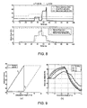
- An optimal sieve overload strategy can be determined on the basis of FIG. 5(a) : If ⁇ d ⁇ ⁇ T ⁇ 12.5 ⁇ s + ⁇ d : open the upper sieve as fast as possible after detection of sieve overload. Close the upper sieve again once the process is stabilized or the disturbance lasted longer than 12.5s ( FIG. 7 ). If 12.5 ⁇ s + ⁇ d ⁇ ⁇ T ⁇ 25.0 ⁇ s : the overload lasts too long to buffer all crop material in the return flow system without an excessive return flow. The upper sieve should be opened at ⁇ T +12.5s and closed again 25s after the start of the overload disturbance ( FIG. 8 ). If ⁇ T ⁇ 25.0 ⁇ s : no action can be taken without violating the maximum allowable return flow rate.
- Above rule proposes to use the return flow system as a buffer that postpones the processing of the superfluous material.
- the disturbance interval ⁇ T does not exceed an interval corresponding to the transport time in the return system.
- the 12.5s restriction in the example above corresponds to the transport delay in the return flow system and avoids overload.
- the single rule control action still achieves a significant loss reduction under condition of a limited disturbance period ( ⁇ 15s) as illustrated in FIG. 9(b) .
- the sieve control strategy was implemented and evaluated in a combine equipped with a loss control system, while harvesting corn.
- a measured sieve control action under automatic control operation is shown in FIG. 10 .
- the return flow was measured at the end of the return flow augers as proposed in EP-A-0 463 240 .
- the return flow control algorithm was triggered three times.
- the active ground keep controller kept sieve overload intervals within the 12.5s period, which made it possible to reduce the sieve losses as proposed in the practical scheme of FIG. 9 .
- the special upper sieve settings further resulted in a significant decrease of the sieve losses and a significant increase of the return flow rate.
- the ground speed sequence that resulted from the grain loss control algorithm was comfortable in contrast to sieve loss control action with fixed settings of the cleaning system 1 (passive cleaning action).
- the above-presented model and algorithm was constructed on the basis of physical insight and measured input-output characteristics.
- the transport time in the return flow system of cleaning sections was identified as an important parameter to describe the system's dynamics.
- a global optimization technique was applied to search for an optimal control of the return flow rate in order to reduce the sieve losses within acceptable operating conditions.
- the optimization technique was applied to reduce the sieve losses in combines by using the return flow system as a material buffer that postpones the handling of superfluous material at a later stage.
- This simple control algorithm realizes an important increase of the dynamic cleaning efficiency and has been shown to be successfully implementable in the field during harvest in automatic grain loss control mode.
Landscapes
- Life Sciences & Earth Sciences (AREA)
- Environmental Sciences (AREA)
- Threshing Machine Elements (AREA)
- Combines (AREA)
- Harvester Elements (AREA)
- Outside Dividers And Delivering Mechanisms For Harvesters (AREA)
Claims (18)
- Verfahren zum Optimieren des Betriebs eines Getreidereinigungssystems in einem Mähdrescher während des Erntens, wobei das Getreidereinigungssystem (1) ein oberes Spreusieb (5) und ein unteres Körnersieb (6) umfasst, die übereinander angeordnet sind, wobei das Verfahren Folgendes umfasst:- Ernten eines Erntematerials und Führen des geernteten Erntematerials zu einem Dresch- und Trennsystem, um gewünschtes Erntematerial von unerwünschtem Erntematerial zu trennen;- Führen von zumindest einem Teil des abgetrennten Erntematerials zu dem Getreidereinigungssystem;- Reinigen des abgetrennten Erntematerials in einem Getreidereinigungssystem durch Führen des Materials über die nachfolgenden Siebe (5, 6), wodurch Material, das nicht aus dem Mähdrescher ausgeworfen wird und das nicht durch das untere Körnersieb (6) hindurch läuft, zum vorderen Ende des Getreidereinigungssystems zurückgeführt wird, um die Reinigungswirkung zu wiederholen, wodurch eine Material-Rücklaufströmung erzeugt wird,dadurch gekennzeichnet, dass das Verfahren weiterhin den Schritt des Einstellens der Stellung des oberen Siebes (5) bei der Feststellung einer Abweichung von einem Schwellenwert für die Erntematerial-Last auf dem oberen Sieb (5) derart umfasst, dass die Material-Rücklaufströmung eingestellt wird.
- Verfahren nach Anspruch 1, bei dem der Schritt des Einstellens der Stellung des oberen Siebes (5) die Änderung der Einstellung der Öffnungen des oberen Siebes über eine geeignete Zeitperiode umfasst.
- Verfahren nach Anspruch 1 oder 2, das die Vergrößerung der Öffnungen des oberen Siebes (5) in dem Getreidereinigungssystem umfasst, wenn der Schwellenwert der Erntematerial-Last auf das obere Sieb (5) überschritten ist, derart, dass die Material-Rücklaufströmung vergrößert wird, wodurch ein vorübergehender Puffer für das überschüssige Erntematerial gebildet und der Siebverlust verringert wird.
- Verfahren nach einem der Ansprüche 1 bis 3, bei dem eine Abweichung von einem Schwellenwert für die Erntematerial-Last auf das obere Sieb (5) mit Hilfe eines Siebverlust-Sensorsystems erfasst wird, das benachbart zu dem hinteren Ende des oberen Siebes (5) vorgesehen ist.
- Verfahren nach einem der Ansprüche 1 bis 3, bei dem die Abweichung von einem Schwellenwert für die Material-Last auf das obere Sieb (5) weiterhin mit Hilfe eines Feld-Neigungs-Sensorsystems erfasst wird.
- Verfahren nach einem der Ansprüche 1 bis 5, bei dem die Einstellungen der Öffnungen des oberen Siebes (5) in dem Getreidereinigungssystem automatisch über eine vorgegebene Zeitperiode bei der Feststellung einer Abweichung von einem Schwellenwert für die Erntematerial-Last auf das obere Sieb (5) verstellt werden.
- Verfahren nach Anspruch 6, bei dem die Verstellung der Einstellungen der Öffnungen des oberen Siebes mit Hilfe eines Sieb-Überlast-Steueralgorithmus gesteuert wird.
- Verfahren nach Anspruch 6 oder 7, bei dem die Verstellung der Position des oberen Siebes (5) die Vergrößerung der Öffnung des oberen Siebes über eine geeignete Zeitperiode umfasst, derart, dass die Material-Rücklaufströmung vergrößert wird, und das danach die Öffnung verkleinert wird, derart, dass die Material-Rücklaufströmung verringert wird.
- Verfahren nach Anspruch 8, bei dem die Öffnung des oberen Siebes unmittelbar vergrößert wird, wenn festgestellt wird, dass die Erntematerial-Last auf das obere Sieb einen Schwellenwert übersteigt.
- Verfahren nach Anspruch 8 oder 9, bei dem die Öffnung des oberen Siebes nach einer Zeitperiode verringert wird, die die Transportverzögerung der Material-Rücklaufströmung nicht übersteigt.
- Verfahren nach Anspruch 10, bei dem die Öffnung des oberen Siebes bei der Feststellung verringert wird, dass die Erntematerial-Last auf das obere Sieb (5) nicht mehr länger dem Schwellenwert übersteigt.
- Verfahren nach Anspruch 7 oder einem hierauf zurückbezogenen Anspruch, bei dem der Sieb-Überlast-Steueralgorithmus in der Lage ist, einen optimalen Sieb-Steuer-Vorgang bei der Feststellung einer Abweichung von einem Schwellenwert für die Erntematerial-Last auf das obere Sieb (5) des Getreidereinigungssystems zu aktivieren.
- Verfahren nach Anspruch 12, bei dem die Sieb-Steuerwirkung eine Öffnungs-Schließ-Siebsteuerwirkung umfasst, die durch den Parameter t0, der die Aktivierungszeit einer speziellen Siebeinstellung darstellt, und durch den Parameter t1 bestimmt ist, der die Zeit darstellt, zu der die Sieb-Nenneinstellung wiederhergestellt wird.
- Verfahren nach Anspruch 12 oder 13, bei dem die Parameter t0 und t1 sinngemäß der folgenden Kostenfunktion V(t0, t1) optimiert werden:

worin u(k) die Strömung des Erntematerials darstellt, das zu dem vorderen Ende des Vorsiebes (4) in einem Getreidereinigungssystem (1) transportiert wird, y((k) die Strömung des Materials darstellt, das die hintere Seite des oberen Siebes (5) verlässt, und x(k) den Rücklauf-Strömungs-Bruchteil des Erntematerials darstellt,
worin
worin
worin das Zeitintervall p (t1 - t0) eine Einbuße für lange Aktivierungsintervalle der speziellen Einstellungen ist. - Verfahren nach einem der Ansprüche 12 bis 14, bei dem ein Satz von Regeln ausgebildet wird, die eine optimale Sieb-Steuerstrategie in Ausdrücken der Siebverluste und der Rücklauf-Strömungs-Beschränkungen auf der Grundlage der Parameter t0 und t1 garantieren, die für unterschiedliche Störungsintervalle Δ t und Erfassungszeiten τd optimiert wurden.
- Verfahren nach Anspruch 15, bei dem die Regeln das Öffnen des oberen Siebes bei einer Feststellung einer Sieb-Überlastung umfassen, bis die Überlast-Erscheinung vergangen ist oder bis die spezielle Reinigungseinstellung über ein Intervall aktiv war, das der Transportzeit in dem Rücklauf-System entspricht.
- Verfahren nach Anspruch 15, bei dem das Störintervall ΔT ein Intervall, dass der Transportzeit in dem Rücklauf-System entspricht, nicht übersteigt.
- Verwendung eines Verfahrens nach einem der vorhergehenden Ansprüche in einem Steueralgorithmus zur Einstellung der Fahrgeschwindigkeit des Mähdreschers bei der Feststellung einer Abweichung von einem weiteren Schwellenwert für Ernteverluste und/oder für eine Einlass-Erntematerial-Last-Rate.
Applications Claiming Priority (2)
| Application Number | Priority Date | Filing Date | Title |
|---|---|---|---|
| GBGB0408931.4A GB0408931D0 (en) | 2004-04-22 | 2004-04-22 | Method for operating a grain cleaning system in a combine harvester |
| GB0408931 | 2004-04-22 |
Publications (2)
| Publication Number | Publication Date |
|---|---|
| EP1588600A1 EP1588600A1 (de) | 2005-10-26 |
| EP1588600B1 true EP1588600B1 (de) | 2009-01-21 |
Family
ID=32344177
Family Applications (1)
| Application Number | Title | Priority Date | Filing Date |
|---|---|---|---|
| EP05103002A Expired - Lifetime EP1588600B1 (de) | 2004-04-22 | 2005-04-15 | Methode zur Betätigung eines Getreidereinigungssystems in einem Mähdrescher |
Country Status (6)
| Country | Link |
|---|---|
| US (2) | US7297052B2 (de) |
| EP (1) | EP1588600B1 (de) |
| AT (1) | ATE421242T1 (de) |
| DE (1) | DE602005012451D1 (de) |
| DK (1) | DK1588600T3 (de) |
| GB (1) | GB0408931D0 (de) |
Families Citing this family (21)
| Publication number | Priority date | Publication date | Assignee | Title |
|---|---|---|---|---|
| GB0408931D0 (en) | 2004-04-22 | 2004-05-26 | Cnh Belgium Nv | Method for operating a grain cleaning system in a combine harvester |
| US7354341B1 (en) * | 2007-03-29 | 2008-04-08 | Cnh America Llc | System and method for detecting an air flow condition indicative of plugging of a discharge apparatus of an agricultural combine |
| GB0714942D0 (en) * | 2007-08-01 | 2007-09-12 | Cnh Belgium Nv | A biomass cleaner improvements in corp harvesting machine and related methods |
| GB0721909D0 (en) * | 2007-11-08 | 2007-12-19 | Cnh Belgium Nv | Apparatus and method for controlling the speed of a combine harvester |
| US8313362B2 (en) * | 2009-04-16 | 2012-11-20 | Cnh America Llc | Agricultural combine with on-board baler and dust suppression capability |
| US8062109B1 (en) * | 2010-08-27 | 2011-11-22 | Deere & Company | Dust suppressor for combine harvester feederhouse |
| US8282453B1 (en) | 2011-05-12 | 2012-10-09 | Cnh America Llc | Tailings distribution control for harvester |
| DE102011052280A1 (de) * | 2011-07-29 | 2013-01-31 | Claas Selbstfahrende Erntemaschinen Gmbh | Vermeidung von Reinigungsverlusten bei starker Seitenneigung |
| US9814184B2 (en) * | 2011-11-09 | 2017-11-14 | Cnh Industrial America Llc | Crop material flow control system |
| US8821229B2 (en) | 2012-12-06 | 2014-09-02 | Cnh Industrial America Llc | Grain cleaning system for an agricultural combine |
| US10045488B2 (en) * | 2016-08-01 | 2018-08-14 | Tribine Industries Llc | Bonus sieves and tailings return for an articulated agricultural harvesting combine |
| US10219439B1 (en) * | 2017-08-14 | 2019-03-05 | Cnh Industrial America Llc | Harvester cleaning system with conveyor enhanced cascades |
| US10448576B2 (en) * | 2017-08-22 | 2019-10-22 | Cnh Industrial America Llc | Adjustable fan based on grain throughput |
| CN110806175B (zh) * | 2019-11-20 | 2021-04-30 | 中国有色金属长沙勘察设计研究院有限公司 | 一种基于三维激光扫描技术的干滩监测方法 |
| US12016257B2 (en) | 2020-02-19 | 2024-06-25 | Sabanto, Inc. | Methods for detecting and clearing debris from planter gauge wheels, closing wheels and seed tubes |
| US12461083B2 (en) | 2020-08-03 | 2025-11-04 | Sabanto, Inc. | Methods for improved agricultural procedures |
| US12137631B2 (en) | 2021-01-22 | 2024-11-12 | Deere & Company | Residue management control system for harvester |
| US12137632B2 (en) | 2021-01-22 | 2024-11-12 | Deere & Company | Residue management control system for harvester |
| CN114902878B (zh) * | 2021-02-09 | 2023-08-01 | 河南中联重科智能农机有限责任公司 | 用于收获机的籽粒损失调节方法、调节装置及收获机 |
| US12201061B2 (en) * | 2021-11-16 | 2025-01-21 | Deere & Company | Adjustable billet deflector |
| US12310285B2 (en) | 2023-02-27 | 2025-05-27 | Deere & Company | Agricultural operation evaluation system and method |
Family Cites Families (19)
| Publication number | Priority date | Publication date | Assignee | Title |
|---|---|---|---|---|
| US4311995A (en) | 1978-03-06 | 1982-01-19 | Sperry Corporation | Sieve overload sensor for alerting the operator of a combine of a sieve overload condition |
| GB2063037B (en) | 1979-11-14 | 1983-05-18 | Sperry Nv | Combine harvesters |
| GB2098446B (en) | 1981-05-20 | 1985-06-12 | Sperry Naamloze Venootschap | Combine harvesters |
| US4527241A (en) * | 1982-08-30 | 1985-07-02 | Sperry Corporation | Automatic combine harvester adjustment system |
| KR870002158B1 (ko) * | 1983-01-11 | 1987-12-14 | 구보다 덱고오 가부시기가이샤 | 예취수확기 |
| US4535788A (en) * | 1984-10-11 | 1985-08-20 | Sperry Corporation | Lateral leveling mechanism for combine cleaning apparatus |
| EP0312655B1 (de) * | 1987-10-22 | 1993-12-22 | New Holland Belgium N.V. | Reinigungsvorrichtung für Mähdrescher |
| DE69024204T2 (de) | 1990-06-23 | 1996-05-23 | Ford New Holland Nv | Durchflussmessgerät |
| DE19912372C1 (de) * | 1999-03-19 | 2000-11-09 | Case Harvesting Sys Gmbh | Vorrichtung zur Messung des Kornanteiles in einer Überkehr eines Mähdreschers |
| US6119442A (en) * | 1999-05-14 | 2000-09-19 | Case Corporation | Combine setting autoadjust with machine vision |
| US6591145B1 (en) * | 2000-09-21 | 2003-07-08 | Bechtel Bwxt Idaho, Llc | Systems and methods for autonomously controlling agricultural machinery |
| US6442916B1 (en) * | 2000-11-17 | 2002-09-03 | Case Corporation | Sensing system for an agricultural combine |
| US6615570B2 (en) | 2001-06-28 | 2003-09-09 | Deere & Company | Header position control with forward contour prediction |
| DE10163947A1 (de) * | 2001-12-22 | 2003-07-03 | Deere & Co | Bordcomputersystem für ein Arbeitsfahrzeug |
| US6726559B2 (en) * | 2002-05-14 | 2004-04-27 | Deere & Company | Harvester with control system considering operator feedback |
| US6761630B1 (en) * | 2003-02-10 | 2004-07-13 | Case, Llc | Method of operation of a sieve adjustment control system for an agricultural combine |
| DE10360597A1 (de) * | 2003-12-19 | 2005-07-28 | Claas Selbstfahrende Erntemaschinen Gmbh | Verfahren und Vorrichtung zur Regelung von Arbeitsorganen eines Mähdreschers |
| GB0408931D0 (en) | 2004-04-22 | 2004-05-26 | Cnh Belgium Nv | Method for operating a grain cleaning system in a combine harvester |
| DE102005014278A1 (de) * | 2005-03-24 | 2006-10-05 | Claas Selbstfahrende Erntemaschinen Gmbh | Verfahren zur Ermittlung eines Ziel-Einstellwerts |
-
2004
- 2004-04-22 GB GBGB0408931.4A patent/GB0408931D0/en not_active Ceased
-
2005
- 2005-03-29 US US11/092,374 patent/US7297052B2/en not_active Expired - Lifetime
- 2005-04-15 EP EP05103002A patent/EP1588600B1/de not_active Expired - Lifetime
- 2005-04-15 AT AT05103002T patent/ATE421242T1/de not_active IP Right Cessation
- 2005-04-15 DE DE602005012451T patent/DE602005012451D1/de not_active Expired - Lifetime
- 2005-04-15 DK DK05103002T patent/DK1588600T3/da active
-
2007
- 2007-01-26 US US11/698,520 patent/US7403846B2/en not_active Expired - Lifetime
Also Published As
| Publication number | Publication date |
|---|---|
| ATE421242T1 (de) | 2009-02-15 |
| US20070135935A1 (en) | 2007-06-14 |
| DK1588600T3 (da) | 2009-03-23 |
| US7297052B2 (en) | 2007-11-20 |
| US20050245300A1 (en) | 2005-11-03 |
| EP1588600A1 (de) | 2005-10-26 |
| GB0408931D0 (en) | 2004-05-26 |
| US7403846B2 (en) | 2008-07-22 |
| DE602005012451D1 (de) | 2009-03-12 |
Similar Documents
| Publication | Publication Date | Title |
|---|---|---|
| US7403846B2 (en) | Method for operating a grain cleaning system in a combine harvester | |
| US6726559B2 (en) | Harvester with control system considering operator feedback | |
| EP1349443B1 (de) | Verfahren zur schätzung des ernteertrages | |
| EP3569050B1 (de) | Verfahren und system zur steuerung der höhe eines landwirtschaftlichen arbeitsgeräts in bezug auf den boden | |
| AU2014201449B2 (en) | Harvester with fuzzy control system for detecting steady crop processing state | |
| US7630808B2 (en) | Method for computing a target setting value | |
| US7308326B2 (en) | Methods of optimizing stochastic processing parameters in crop harvesting machines | |
| EP3672391B1 (de) | Verstellbares gebläse auf der grundlage des korndurchsatzes | |
| EP3687276B1 (de) | Automatische häckselwannensteuerung | |
| US10897848B2 (en) | Combine harvester with fan speed adjust | |
| US20250221337A1 (en) | Devices and methods for automated concave covers | |
| JPH10304734A (ja) | コンバイン等の倒伏判定装置 | |
| US20250248332A1 (en) | Detecting Multiple Specific Issues From A Single User Input | |
| EP4544898A1 (de) | Verfahren zur kalibrierung eines überkehrsensors in einem mähdrescher | |
| US20260076303A1 (en) | Combine harvester feed rate control |
Legal Events
| Date | Code | Title | Description |
|---|---|---|---|
| PUAI | Public reference made under article 153(3) epc to a published international application that has entered the european phase |
Free format text: ORIGINAL CODE: 0009012 |
|
| AK | Designated contracting states |
Kind code of ref document: A1 Designated state(s): AT BE BG CH CY CZ DE DK EE ES FI FR GB GR HU IE IS IT LI LT LU MC NL PL PT RO SE SI SK TR |
|
| AX | Request for extension of the european patent |
Extension state: AL BA HR LV MK YU |
|
| 17P | Request for examination filed |
Effective date: 20060403 |
|
| AKX | Designation fees paid |
Designated state(s): AT BE BG CH CY CZ DE DK EE ES FI FR GB GR HU IE IS IT LI LT LU MC NL PL PT RO SE SI SK TR |
|
| 17Q | First examination report despatched |
Effective date: 20070420 |
|
| GRAP | Despatch of communication of intention to grant a patent |
Free format text: ORIGINAL CODE: EPIDOSNIGR1 |
|
| GRAS | Grant fee paid |
Free format text: ORIGINAL CODE: EPIDOSNIGR3 |
|
| GRAA | (expected) grant |
Free format text: ORIGINAL CODE: 0009210 |
|
| AK | Designated contracting states |
Kind code of ref document: B1 Designated state(s): AT BE BG CH CY CZ DE DK EE ES FI FR GB GR HU IE IS IT LI LT LU MC NL PL PT RO SE SI SK TR |
|
| REG | Reference to a national code |
Ref country code: GB Ref legal event code: FG4D |
|
| REG | Reference to a national code |
Ref country code: CH Ref legal event code: EP |
|
| REG | Reference to a national code |
Ref country code: IE Ref legal event code: FG4D |
|
| REF | Corresponds to: |
Ref document number: 602005012451 Country of ref document: DE Date of ref document: 20090312 Kind code of ref document: P |
|
| REG | Reference to a national code |
Ref country code: DK Ref legal event code: T3 |
|
| PG25 | Lapsed in a contracting state [announced via postgrant information from national office to epo] |
Ref country code: NL Free format text: LAPSE BECAUSE OF FAILURE TO SUBMIT A TRANSLATION OF THE DESCRIPTION OR TO PAY THE FEE WITHIN THE PRESCRIBED TIME-LIMIT Effective date: 20090121 |
|
| NLV1 | Nl: lapsed or annulled due to failure to fulfill the requirements of art. 29p and 29m of the patents act | ||
| PG25 | Lapsed in a contracting state [announced via postgrant information from national office to epo] |
Ref country code: SI Free format text: LAPSE BECAUSE OF FAILURE TO SUBMIT A TRANSLATION OF THE DESCRIPTION OR TO PAY THE FEE WITHIN THE PRESCRIBED TIME-LIMIT Effective date: 20090121 Ref country code: LT Free format text: LAPSE BECAUSE OF FAILURE TO SUBMIT A TRANSLATION OF THE DESCRIPTION OR TO PAY THE FEE WITHIN THE PRESCRIBED TIME-LIMIT Effective date: 20090121 Ref country code: FI Free format text: LAPSE BECAUSE OF FAILURE TO SUBMIT A TRANSLATION OF THE DESCRIPTION OR TO PAY THE FEE WITHIN THE PRESCRIBED TIME-LIMIT Effective date: 20090121 Ref country code: ES Free format text: LAPSE BECAUSE OF FAILURE TO SUBMIT A TRANSLATION OF THE DESCRIPTION OR TO PAY THE FEE WITHIN THE PRESCRIBED TIME-LIMIT Effective date: 20090502 |
|
| PG25 | Lapsed in a contracting state [announced via postgrant information from national office to epo] |
Ref country code: IS Free format text: LAPSE BECAUSE OF FAILURE TO SUBMIT A TRANSLATION OF THE DESCRIPTION OR TO PAY THE FEE WITHIN THE PRESCRIBED TIME-LIMIT Effective date: 20090521 Ref country code: SE Free format text: LAPSE BECAUSE OF FAILURE TO SUBMIT A TRANSLATION OF THE DESCRIPTION OR TO PAY THE FEE WITHIN THE PRESCRIBED TIME-LIMIT Effective date: 20090421 Ref country code: PT Free format text: LAPSE BECAUSE OF FAILURE TO SUBMIT A TRANSLATION OF THE DESCRIPTION OR TO PAY THE FEE WITHIN THE PRESCRIBED TIME-LIMIT Effective date: 20090622 Ref country code: PL Free format text: LAPSE BECAUSE OF FAILURE TO SUBMIT A TRANSLATION OF THE DESCRIPTION OR TO PAY THE FEE WITHIN THE PRESCRIBED TIME-LIMIT Effective date: 20090121 Ref country code: AT Free format text: LAPSE BECAUSE OF FAILURE TO SUBMIT A TRANSLATION OF THE DESCRIPTION OR TO PAY THE FEE WITHIN THE PRESCRIBED TIME-LIMIT Effective date: 20090121 |
|
| PG25 | Lapsed in a contracting state [announced via postgrant information from national office to epo] |
Ref country code: EE Free format text: LAPSE BECAUSE OF FAILURE TO SUBMIT A TRANSLATION OF THE DESCRIPTION OR TO PAY THE FEE WITHIN THE PRESCRIBED TIME-LIMIT Effective date: 20090121 Ref country code: CZ Free format text: LAPSE BECAUSE OF FAILURE TO SUBMIT A TRANSLATION OF THE DESCRIPTION OR TO PAY THE FEE WITHIN THE PRESCRIBED TIME-LIMIT Effective date: 20090121 |
|
| PLBE | No opposition filed within time limit |
Free format text: ORIGINAL CODE: 0009261 |
|
| STAA | Information on the status of an ep patent application or granted ep patent |
Free format text: STATUS: NO OPPOSITION FILED WITHIN TIME LIMIT |
|
| PG25 | Lapsed in a contracting state [announced via postgrant information from national office to epo] |
Ref country code: SK Free format text: LAPSE BECAUSE OF FAILURE TO SUBMIT A TRANSLATION OF THE DESCRIPTION OR TO PAY THE FEE WITHIN THE PRESCRIBED TIME-LIMIT Effective date: 20090121 Ref country code: RO Free format text: LAPSE BECAUSE OF FAILURE TO SUBMIT A TRANSLATION OF THE DESCRIPTION OR TO PAY THE FEE WITHIN THE PRESCRIBED TIME-LIMIT Effective date: 20090121 |
|
| REG | Reference to a national code |
Ref country code: CH Ref legal event code: PL |
|
| 26N | No opposition filed |
Effective date: 20091022 |
|
| PG25 | Lapsed in a contracting state [announced via postgrant information from national office to epo] |
Ref country code: CH Free format text: LAPSE BECAUSE OF NON-PAYMENT OF DUE FEES Effective date: 20090430 Ref country code: BG Free format text: LAPSE BECAUSE OF FAILURE TO SUBMIT A TRANSLATION OF THE DESCRIPTION OR TO PAY THE FEE WITHIN THE PRESCRIBED TIME-LIMIT Effective date: 20090421 Ref country code: LI Free format text: LAPSE BECAUSE OF NON-PAYMENT OF DUE FEES Effective date: 20090430 |
|
| REG | Reference to a national code |
Ref country code: IE Ref legal event code: MM4A |
|
| PG25 | Lapsed in a contracting state [announced via postgrant information from national office to epo] |
Ref country code: IE Free format text: LAPSE BECAUSE OF NON-PAYMENT OF DUE FEES Effective date: 20090415 Ref country code: MC Free format text: LAPSE BECAUSE OF NON-PAYMENT OF DUE FEES Effective date: 20090430 |
|
| PG25 | Lapsed in a contracting state [announced via postgrant information from national office to epo] |
Ref country code: GR Free format text: LAPSE BECAUSE OF FAILURE TO SUBMIT A TRANSLATION OF THE DESCRIPTION OR TO PAY THE FEE WITHIN THE PRESCRIBED TIME-LIMIT Effective date: 20090422 |
|
| PG25 | Lapsed in a contracting state [announced via postgrant information from national office to epo] |
Ref country code: LU Free format text: LAPSE BECAUSE OF NON-PAYMENT OF DUE FEES Effective date: 20090415 |
|
| PG25 | Lapsed in a contracting state [announced via postgrant information from national office to epo] |
Ref country code: HU Free format text: LAPSE BECAUSE OF FAILURE TO SUBMIT A TRANSLATION OF THE DESCRIPTION OR TO PAY THE FEE WITHIN THE PRESCRIBED TIME-LIMIT Effective date: 20090722 |
|
| PG25 | Lapsed in a contracting state [announced via postgrant information from national office to epo] |
Ref country code: TR Free format text: LAPSE BECAUSE OF FAILURE TO SUBMIT A TRANSLATION OF THE DESCRIPTION OR TO PAY THE FEE WITHIN THE PRESCRIBED TIME-LIMIT Effective date: 20090121 |
|
| PG25 | Lapsed in a contracting state [announced via postgrant information from national office to epo] |
Ref country code: CY Free format text: LAPSE BECAUSE OF FAILURE TO SUBMIT A TRANSLATION OF THE DESCRIPTION OR TO PAY THE FEE WITHIN THE PRESCRIBED TIME-LIMIT Effective date: 20090121 |
|
| REG | Reference to a national code |
Ref country code: DE Ref legal event code: R082 Ref document number: 602005012451 Country of ref document: DE Representative=s name: PATENTANWAELTE WALLACH, KOCH & PARTNER, DE |
|
| REG | Reference to a national code |
Ref country code: DE Ref legal event code: R082 Ref document number: 602005012451 Country of ref document: DE Representative=s name: PATENTANWAELTE WALLACH, KOCH & PARTNER, DE Effective date: 20140428 Ref country code: DE Ref legal event code: R081 Ref document number: 602005012451 Country of ref document: DE Owner name: CNH INDUSTRIAL BELGIUM NV, BE Free format text: FORMER OWNER: CNH BELGIUM NV, ZEDELGEM, BE Effective date: 20140428 Ref country code: DE Ref legal event code: R082 Ref document number: 602005012451 Country of ref document: DE Representative=s name: PATENTANWAELTE WALLACH, KOCH, DR. HAIBACH, FEL, DE Effective date: 20140428 |
|
| REG | Reference to a national code |
Ref country code: FR Ref legal event code: CD Owner name: CNH INDUSTRIAL BELGIUM NV Effective date: 20140725 |
|
| PGFP | Annual fee paid to national office [announced via postgrant information from national office to epo] |
Ref country code: DK Payment date: 20150423 Year of fee payment: 11 |
|
| REG | Reference to a national code |
Ref country code: DE Ref legal event code: R084 Ref document number: 602005012451 Country of ref document: DE |
|
| REG | Reference to a national code |
Ref country code: FR Ref legal event code: PLFP Year of fee payment: 12 |
|
| REG | Reference to a national code |
Ref country code: GB Ref legal event code: 746 Effective date: 20160316 |
|
| REG | Reference to a national code |
Ref country code: DK Ref legal event code: EBP Effective date: 20160430 |
|
| REG | Reference to a national code |
Ref country code: FR Ref legal event code: PLFP Year of fee payment: 13 |
|
| PG25 | Lapsed in a contracting state [announced via postgrant information from national office to epo] |
Ref country code: DK Free format text: LAPSE BECAUSE OF NON-PAYMENT OF DUE FEES Effective date: 20160430 |
|
| REG | Reference to a national code |
Ref country code: FR Ref legal event code: PLFP Year of fee payment: 14 |
|
| PGFP | Annual fee paid to national office [announced via postgrant information from national office to epo] |
Ref country code: PL Payment date: 20180427 Year of fee payment: 8 Ref country code: FR Payment date: 20180410 Year of fee payment: 14 |
|
| PGFP | Annual fee paid to national office [announced via postgrant information from national office to epo] |
Ref country code: GB Payment date: 20180403 Year of fee payment: 14 |
|
| PGFP | Annual fee paid to national office [announced via postgrant information from national office to epo] |
Ref country code: BE Payment date: 20190408 Year of fee payment: 15 |
|
| GBPC | Gb: european patent ceased through non-payment of renewal fee |
Effective date: 20190415 |
|
| PG25 | Lapsed in a contracting state [announced via postgrant information from national office to epo] |
Ref country code: GB Free format text: LAPSE BECAUSE OF NON-PAYMENT OF DUE FEES Effective date: 20190415 |
|
| PG25 | Lapsed in a contracting state [announced via postgrant information from national office to epo] |
Ref country code: FR Free format text: LAPSE BECAUSE OF NON-PAYMENT OF DUE FEES Effective date: 20190430 |
|
| PG25 | Lapsed in a contracting state [announced via postgrant information from national office to epo] |
Ref country code: IT Free format text: LAPSE BECAUSE OF NON-PAYMENT OF DUE FEES Effective date: 20190415 |
|
| REG | Reference to a national code |
Ref country code: DE Ref legal event code: R082 Ref document number: 602005012451 Country of ref document: DE Representative=s name: MEISSNER BOLTE PATENTANWAELTE RECHTSANWAELTE P, DE |
|
| REG | Reference to a national code |
Ref country code: BE Ref legal event code: MM Effective date: 20200430 |
|
| PG25 | Lapsed in a contracting state [announced via postgrant information from national office to epo] |
Ref country code: BE Free format text: LAPSE BECAUSE OF NON-PAYMENT OF DUE FEES Effective date: 20200430 |
|
| PGFP | Annual fee paid to national office [announced via postgrant information from national office to epo] |
Ref country code: DE Payment date: 20240425 Year of fee payment: 20 |
|
| REG | Reference to a national code |
Ref country code: DE Ref legal event code: R071 Ref document number: 602005012451 Country of ref document: DE |