EP1588117B1 - Vorrichtung für schiessplätze - Google Patents
Vorrichtung für schiessplätze Download PDFInfo
- Publication number
- EP1588117B1 EP1588117B1 EP03786486A EP03786486A EP1588117B1 EP 1588117 B1 EP1588117 B1 EP 1588117B1 EP 03786486 A EP03786486 A EP 03786486A EP 03786486 A EP03786486 A EP 03786486A EP 1588117 B1 EP1588117 B1 EP 1588117B1
- Authority
- EP
- European Patent Office
- Prior art keywords
- housing
- layer
- bottom layer
- angle
- segment
- Prior art date
- Legal status (The legal status is an assumption and is not a legal conclusion. Google has not performed a legal analysis and makes no representation as to the accuracy of the status listed.)
- Expired - Lifetime
Links
- 239000008187 granular material Substances 0.000 claims abstract description 31
- 230000009969 flowable effect Effects 0.000 claims abstract description 7
- 238000009434 installation Methods 0.000 claims abstract description 4
- XLYOFNOQVPJJNP-UHFFFAOYSA-N water Substances O XLYOFNOQVPJJNP-UHFFFAOYSA-N 0.000 claims description 5
- 230000001012 protector Effects 0.000 claims 1
- 239000000463 material Substances 0.000 description 29
- 239000004576 sand Substances 0.000 description 12
- 229910000831 Steel Inorganic materials 0.000 description 5
- 239000004033 plastic Substances 0.000 description 5
- 229920003023 plastic Polymers 0.000 description 5
- 239000010959 steel Substances 0.000 description 5
- 238000010276 construction Methods 0.000 description 4
- 238000011109 contamination Methods 0.000 description 4
- 239000002245 particle Substances 0.000 description 3
- 239000004698 Polyethylene Substances 0.000 description 2
- 230000007613 environmental effect Effects 0.000 description 2
- 239000003344 environmental pollutant Substances 0.000 description 2
- 238000002386 leaching Methods 0.000 description 2
- 231100000719 pollutant Toxicity 0.000 description 2
- -1 polyethylene Polymers 0.000 description 2
- 229920000573 polyethylene Polymers 0.000 description 2
- 239000011435 rock Substances 0.000 description 2
- 230000004075 alteration Effects 0.000 description 1
- 230000000712 assembly Effects 0.000 description 1
- 238000000429 assembly Methods 0.000 description 1
- QVGXLLKOCUKJST-UHFFFAOYSA-N atomic oxygen Chemical compound [O] QVGXLLKOCUKJST-UHFFFAOYSA-N 0.000 description 1
- 238000004891 communication Methods 0.000 description 1
- 238000009833 condensation Methods 0.000 description 1
- 230000005494 condensation Effects 0.000 description 1
- 239000004035 construction material Substances 0.000 description 1
- 239000000356 contaminant Substances 0.000 description 1
- 239000000428 dust Substances 0.000 description 1
- 238000005516 engineering process Methods 0.000 description 1
- 238000007667 floating Methods 0.000 description 1
- 239000012530 fluid Substances 0.000 description 1
- 230000006870 function Effects 0.000 description 1
- 150000002611 lead compounds Chemical class 0.000 description 1
- 239000000203 mixture Substances 0.000 description 1
- 229910052760 oxygen Inorganic materials 0.000 description 1
- 239000001301 oxygen Substances 0.000 description 1
- 230000000149 penetrating effect Effects 0.000 description 1
- 230000035515 penetration Effects 0.000 description 1
- 239000000843 powder Substances 0.000 description 1
- 239000003223 protective agent Substances 0.000 description 1
- 230000009993 protective function Effects 0.000 description 1
- 238000005086 pumping Methods 0.000 description 1
- 230000000284 resting effect Effects 0.000 description 1
- 238000009420 retrofitting Methods 0.000 description 1
- 239000007787 solid Substances 0.000 description 1
- 239000004575 stone Substances 0.000 description 1
- 239000000126 substance Substances 0.000 description 1
- 238000006467 substitution reaction Methods 0.000 description 1
- 239000002352 surface water Substances 0.000 description 1
- 239000002023 wood Substances 0.000 description 1
Images

Classifications
-
- F—MECHANICAL ENGINEERING; LIGHTING; HEATING; WEAPONS; BLASTING
- F41—WEAPONS
- F41J—TARGETS; TARGET RANGES; BULLET CATCHERS
- F41J13/00—Bullet catchers
Definitions
- the present invention relates to an apparatus for installation at shooting ranges and has a non-flowable granulate material that is used as a stopping material for projectiles.
- the present invention provides a solution to the above-outlined problems. More particularly, the apparatus of the present invention is for installation at shooting ranges.
- the apparatus has a housing that has a resilient top layer and a flexible bottom layer.
- the bottom layer extends along an inclined bottom surface and over an-upwardly protruding support member to a front side.
- the top layer is attached to the bottom layer at the front side to form a container.
- a stationary non-flowable granulated material is tightly packed in the container for adhering to projectiles that have penetrated through the top layer.
- the inclined bottom surface is inclined at an angle relative to a horizontal plane. The angle is less than an angle of repose of the granulated material.
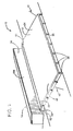
- the shooting range apparatus 10 of the present invention has a lower watertight sloping bullet catcher housing 12 and an upper bullet catcher housing 14 that may be spaced, by for example a 30 centimeters gap 52, from the housing 12.
- the housing 12 includes a non-flowable granulate material 16 that is packed in the housing 12.
- the housing 12 may be placed on a bottom surface 28 of a sloping ground segment 18 at an angle 20 that, preferably, is less an angle of repose 23 of the granulated 16 and same as the housing 12.
- the angle 20 may be about 30 degrees or any other suitable angle.
- the angle of repose may mean the equilibrium angle of the granulated material 16 at which the granulated material 16 may start to flow due to the gravitational forces overtaking the frictional forces between the granulate particles and the frictional forces between the granulated material 16 and the supporting surface.
- the angle of repose may be the angle from the horizontal that the granulated material 16 assumes when at rest, from the top of the pile to its base.
- the angle of repose may be greater than the angle of slide that may mean the angle to the horizontal at which the granulated material 16 will begin to slide on a smooth, flat surface, by its own weight.
- the granulated material 16 is tightly packed in the housing 12.
- the granulated material 16 may include a stationary non-flowable rubber material that is tightly enclosed in the housing 12 to prevent lead pollution from lead bullets and other projectiles 22. Because the rubber material 16 is non-flowable, the rubber material 16 retains the projectiles 22 that penetrate into the rubber material 16 and the projectiles 22 may adhere to and become part of the rubber material 16 since the rubber material 16 is not free-flowable and the sloping angle of the support surface is below the angle of repose of the granulated material 16.
- the housing 12 has a resilient top layer 24 and a flexible, i.e. bendable, bottom rubber layer 26.
- the top layer 24 may extend across the entire housing 12 and be made of a material that permits the penetration of the projectiles 22 while preventing any granulated material 16 from escaping the housing 12.
- the bottom layer 26 rests on the inclined bottom surface 28 and extends up over a supporting segment 30 and over an upside down U-shaped member 32.
- the supporting segment 30 can be any supporting member or wall made of wood, sand, stone, bags or any other suitable supporting material.
- the bottom layer 26 is watertight as long as the bottom layer 26 separates the granulated material 16 from the ground or support surface.
- the bottom layer 26 and the top layer 24 may together be tightly attached to a front side 34 of the member 32 with a fastener 35 that may extend along the entire width W of the housing 12. In this way, the layer 24 and the bottom layer 26 form a watertight container 25.
- a gap 46 may be formed between the bottom layer 26 and the supporting segment 30.
- the gap may be defined by a polyethylene member that supports the granulate material.
- a drainage pipe 36 Adjacent to a corner 44 between the bottom surface 28 and the segment 30 is a drainage pipe 36 located.
- the pipe 36 that may extend along the entire width W of the housing 12, is, at one end of the pipe, in fluid communication with an outlet tube 38 that has a lid 41.
- the lid 41 may be opened for withdrawing or pumping any water and pollutants that may have gathered in the drainage pipe 36. It may also be possible to associate the pipe 36 to an outlet for a safe and automatic drainage of the pollutants.
- a vertical steel tube 39 that has a plastic skin 40 extends from a concrete slab 42 into the U-shaped member 32 and provides support for the members 30, 32.
- the slab 42 may extend along an entire width W of the housing 12 and the slab 42 supports a plurality of tubes 39 that are spaced apart about 120 centimeters from one another.
- the U-shaped member 32 may also extend along the entire width W of the housing 12. Instead of using concrete slab, it is possible to use anchors or any other suitable technology.
- the housing 12 has a sloping segment 48 and a substantially horizontal segment 50 extending towards a front part or wall 54 of the top housing 14.
- the gap 52 is formed between a front wall 54 of the housing 14 and the backend 56 of the horizontal segment 50. It is possible to add another sloping housing behind the housing 14 that is similar to the housing 12.
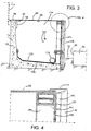
- Fig. 3 shows a detailed cross sectional view of the housing 14.
- the housing 14 has an L-shaped concrete slab 58 and a lid 60 that are in operative engagement with the front wall 54.
- Vertical protecting plates 62 and 64 extend downwardly from the lid 60 to prevent projectiles from penetrating between the top surface 66 of the slab 58 and the bottom surface 68 of the lid 60.
- the plate 64 is longer than the plate 62.
- the plate 64 also has a protective function, should the level of the granulated 116 be lowered over time so that a gap is created between the top surface of the granulate material and the lid 60.
- the plate 64 prevents projectiles from destroying the L-shaped box.
- a watertight layer 120 is disposed along a floor section 122 of the concrete 58. Similar to the housing 12, a drainage pipe 124 may be disposed at the lowest point of the housing 14.
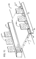
- Fig. 4 is a detailed view of Fig. 3 and shows a horizontal steel bar 100 surrounded by a plastic pipe 102 that rests on a vertical steel bar 104.
- the steel bar 100 may extend along the entire width W while the bars 104 may be separated by a distance of about 1.5 meters between each vertical bar 104.
- the housing 12 has a resilient rubber front layer 106 that permits projectiles to pass there through and a plastic profile 108 is placed adjacent to the pipe 102 and plastic profiles 110 are in operative engagement with the front layer 106 of the front wall 54.
- a wedge 112 is placed on top of the profile 108 to guide projectiles into the granulated material 116 of the housing 14. Projectiles that travel above the wedge 112 may hit the targets 114.
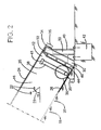
- Fig. 5 shows the trap assembly used for retrofitting a contaminated shooting range 77.
- a sloping sandbank 74 is contaminated with projectiles 76.
- a section 78 that is about 0.5-0.6 meters deep is contaminated and is removed.
- the housing 12 may be used to replace the section 78 to prevent future lead contamination.
- the angle 80 is below the angle of repose of the granulated material 16 disposed inside the housing 12.
- the granulated material 16 often has an angle of repose that is steeper than the sand 84 of the sandbank so if the angle of repose of the sand is used this angle is less than the angle of repose of the granulated material 16.
- a sloping sand surface 82 is thus used to support the housing 12.
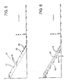
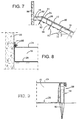
- Fig. 7 is a cross-sectional view of the housing 12 bearing against a vertical concrete wall segment 86.
- the housing 12 has a side wall segment 90 with anchors 92.
- the housing 12 has the horizontal segment 50 that is used to catch projectiles that penetrate the top layer 24 at the upper end 51 of the housing 12.
- the segment 50 is also filled with granulated 16.
- Fig. 8 is a detailed view of Fig. 7 .
- the top layer 24 and the bottom layer 26 are tightly joined and attached to the wall segment 86 by steel fastener assemblies 88.
- the bottom layer 26 rests upon the sloping sand or filling material 94 that has the angle 20 below the angle of repose of the granulated 16, as indicated above.
- Fig. 9 is a detailed view of Fig. 7 and shows a support member 96 and an upside down U-shaped member 98.
- the top layer 24 and the bottom layer 26 are tightly joined in front of the member 98 similar to the attachment to U-shaped member 34 described above.
- the apparatus 10 may have an extended watertight bottom layer 27 of the bottom layer 26 that extends on both sides of the container 25 having the top layer 24 so that further contamination of the ground segment 122 is prevented or reduced.
- the region 120 may include sand, rocks or any other suitable filling material.
- the extended bottom layer 27 prevents the leaching of lead and other contaminants in the previously contaminated ground segment 122. In other words, the extended bottom layer 27 prevents water 123 in the region 120 from entering into the ground segment 122 that can create further contamination of the lead bullets 125 that may already exist in the ground segment 122. Another function of the extended bottom layer 27 is to prevent the leaching of lead from the region 120 into the ground segment 122.
- the bottom layer 26 may be attached to the support members 96 by a suitable elongate member 124 so that the top layer 24 and the bottom layer 26 form a tight seal.
- Fig. 11 is substantially similar to the apparatus 10 in Fig. 10 except that the top layer 24 is supported by a sand- or rock rise 126 and the bottom layer 26 extends over and beyond the rise 126. The top layer 24 extends over and beyond the rise 126.
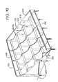
- Fig. 12 shows a shooting range apparatus 200 that has round horizontal support bars 202 for supporting a bottom layer 226 for supporting a granulated material 216 that is placed below a resilient top layer 224.
- the bottom layer 226 may form a wavy shape due to the weight of the granulated rubber material 216 and the lack of support between the beams 202. Only a corner of the granulated material 216 and the layer 224 are shown in Fig. 12 for clarity.
- the bottom layer 226 is supported of vertical poles 230 so that the bottom layer 226 is disposed at an angle beta 228 that is less than the angle of repose of the granulated material 216.
- the apparatus 200 may have vertical sidewalls 232, a front wall 234 and a back wall 236 to hold the material 216 therein.
- Fig. 13 shows an alternative embodiment 300 that is substantially similar-to the apparatus 10 shown in Fig. 1 .
- the apparatus 300 has a bullet diverting member 302 placed below the front wall.
- the member 302 has a sloping segment 304 and a vertical segment 306 so that when bullets hit the sloping segment 304 they are diverted towards the segment 306 and then away from the apparatus 300.
- the sloping and vertical segment may be protected against ricochets by a layer of a self-healing material mounted in distance from the segments.
- the apparatus 300 also has targets 308 shown at the member 302 and targets 310 on top of a rectangular housing 312. The segment 306 prevents the bullets from bouncing against the segment 304 and into the targets 308.
- the granulated stopping material preferably consists of particulate solids with suitable properties to stop incoming projectiles without creating lead-dust.
- Such materials can preferably be elastomeric materials designed into shapes of granules, powder or a gradation with both components or consisting of other materials with similar properties.
- the granulated stopping material may be placed on a surface of high friction against the stopping-material and/or supplied with conformities over or under this surface to hold the granulated stopping material in place to prevent it from sliding down.
- This angle of slide may be kept smaller than the angle of repose of the stopping-material itself to prevents the material from moving downwardly at impact.
- the cover that covers the stopping material supports the stopping-material to stay in place through additional weight.
- a supporting construction can be of any shape and made from any construction material that has enough capability to hold the weight of the box in the desired angle, and will become the same sliding angle as the bottom surface.
- the angle of repose of the sand may be the limit of which suitable angle may be used since the angle of repose of sand is relatively low.
- the supporting construction does not have to be a uniform surface but can be made of supporting round beams spaced with partially open distances.
- the bottom layer may rest on the round beams as hanging carpets supporting the granulated stopping material or resting on a rough surface like a natural dirt segment or an old range-segment of sand.
- the bottom layer is watertight.
- the bottom layer may also be sealed trough heat or chemical bonding or mechanically tightening together with the top layer.
- the top layer may be fastened to the supporting frame or held in place by shovelling dirt over the edges.
- the bottom layer that may be disposed outside the frame may be held in place by the material that can be shot at, and a layer that is heavy enough to hold it down without permitting projectiles passing the bottom layer.
- the principle is to let the contaminated sand stay under the bottom layer under conditions that the bottom layer which is watertight will stop further contamination as water will not enter and thus cannot leach out lead from the sand that is disposed underneath.
- the bottom layer should be connected watertight at the highest level to a wall, or the layer should be enlarged to cover the area to the beginning of the slope at the backside for the surface water to stream freely on the backside or the layer to be connected to a drain trough an open ditch or via a drainpipe.
- the box-type catcher with lid may be used with fire-protective agents in a floating form as this can be circulated through the drainage pipe and may be uniformly spread without external mixing. Because of oxygen having access to the space under the lid, it is important to have a fire protection when shooting with tracers. The same can be adapted to the sealed sloping version with drainage if extra protection is desired.
- the frames of recycled polyethylene plastic or rubber material are free from ricochets.
Landscapes
- Engineering & Computer Science (AREA)
- General Engineering & Computer Science (AREA)
- Aiming, Guidance, Guns With A Light Source, Armor, Camouflage, And Targets (AREA)
- Catching Or Destruction (AREA)
- Crystals, And After-Treatments Of Crystals (AREA)
- Glass Compositions (AREA)
- Glanulating (AREA)
- Devices And Processes Conducted In The Presence Of Fluids And Solid Particles (AREA)
Claims (13)
- Vorrichtung zur Installation an Schießständen, umfassend:ein Gehäuse (12, 14) mit einer elastischen Deckschicht (24) und einer flexiblen Bodenschicht (26), welche Bodenschicht (26) sich entlang einer geneigten Bodenfläche (28) und über ein emporragendes Stützorgan (30) zu einer Vorderseite (34) erstreckt, welche Deckschicht (24) an der Bodenschicht (26) an der Vorderseite (34) befestigt ist, um einen wasserdichten Container zu bilden (25);ein stationäres nicht fließfähiges granuliertes Material (16, 116), das im Container (25) dicht gepackt ist, um die Projektile (22, 117) festzuhalten, die die Deckschicht (24) durchschlagen haben; unddie geneigte Bodenfläche (28) um einen Winkel (20) im Verhältnis zu einer horizontalen Ebene (21) geneigt ist, welcher Winkel (20) kleiner als der Böschungswinkel (23) des granulierten Materials (16) ist.
- Vorrichtung nach Anspruch 1, worin das Gehäuse (12) in operativer Verbindung mit einem rechteckigen Gehäuse (14) steht, das mit einem granulierten Material (116) gefüllt ist und eine elastische Vorderschicht (106) aufweist, die von Projektilen (117) durchschlagen werden kann.
- Vorrichtung Anspruch 2, worin das Gehäuse (12) ein horizontales Segment (50) aufweist, das an einem oberen Ende (51) des Gehäuses (12) und vor der Vorderschicht (106) angeordnet ist, welches Segment (50) und die Vorderschicht (106) einen dazwischen gebildeten Spalt (52) aufweisen.
- Vorrichtung nach Anspruch 1, worin ein Stützorgan (32) auf dem Organ (30) positioniert ist und das Organ (32) sich über die gesamte Breite (W) des Gehäuses erstreckt, welches Gehäuse (12) darin angeordnete Entwässerungsmittel (36) aufweist.
- Vorrichtung nach Anspruch 4, worin die Bodenschicht (26) und die Deckschicht (24) am Organ (32) befestigt sind.
- Vorrichtung nach Anspruch 2, worin das Gehäuse (14) eine wasserdichte Bodenschicht (1210) aufweist, die sich aufwärts an einem Abschnitt einer Innenseite der Vorderschicht (106) erstreckt.
- Vorrichtung nach Anspruch 1, worin das Organ (30) im Wesentlichen senkrecht zur Bodenfläche (28) und Bodenschicht (26) ist.
- Vorrichtung nach Anspruch 2, worin das Gehäuse (14) eine L-förmige Betonwand (58) zur Auflage eines Deckels (60) aufweist.
- Vorrichtung nach Anspruch 8, worin der Deckel (60) einen nach unten hervorstehenden Schutz (64) aufweist.
- Vorrichtung nach Anspruch 1, worin die Vorrichtung einen geneigten Kugelabweiser hat, (302), der unterhalb eines Satzes von Zielscheiben (308) angeordnet ist.
- Vorrichtung nach Anspruch 1, worin das Gehäuse (12) ein horizontales Segment (50) aufweist, das an einem oberen Ende (51) des Gehäuses (12) angeordnet ist.
- Vorrichtung nach Anspruch 1, worin die Bodenschicht (26) am Kasten (12) befestigt ist und einen außerhalb des Kastens (12) angeordneten Bereich (27) hat.
- Vorrichtung nach Anspruch 1, worin sich die Bodenschicht (26) in einer Richtung erstreckt, um Wasser daher daraus abzuweisen.
Applications Claiming Priority (3)
| Application Number | Priority Date | Filing Date | Title |
|---|---|---|---|
| US31988203P | 2003-01-20 | 2003-01-20 | |
| US319882P | 2003-01-20 | ||
| PCT/SE2003/002096 WO2004065887A1 (en) | 2003-01-20 | 2003-12-29 | Apparatus for shooting ranges |
Publications (2)
| Publication Number | Publication Date |
|---|---|
| EP1588117A1 EP1588117A1 (de) | 2005-10-26 |
| EP1588117B1 true EP1588117B1 (de) | 2009-03-18 |
Family
ID=32770146
Family Applications (1)
| Application Number | Title | Priority Date | Filing Date |
|---|---|---|---|
| EP03786486A Expired - Lifetime EP1588117B1 (de) | 2003-01-20 | 2003-12-29 | Vorrichtung für schiessplätze |
Country Status (8)
| Country | Link |
|---|---|
| US (1) | US7185892B2 (de) |
| EP (1) | EP1588117B1 (de) |
| AT (1) | ATE426141T1 (de) |
| AU (1) | AU2003295305A1 (de) |
| CA (1) | CA2513423C (de) |
| DE (1) | DE60326769D1 (de) |
| NO (1) | NO20053889L (de) |
| WO (1) | WO2004065887A1 (de) |
Families Citing this family (5)
| Publication number | Priority date | Publication date | Assignee | Title |
|---|---|---|---|---|
| SE536516C2 (sv) * | 2012-06-04 | 2014-01-21 | Stapp Internat Ab | Urlakningsskydd för skjutbanor utomhus |
| JP5802174B2 (ja) * | 2012-07-02 | 2015-10-28 | バブ日立工業株式会社 | 傾斜式バックストップ構造 |
| SE536869C2 (sv) | 2012-10-26 | 2014-10-14 | Stapp Internat Ab | Projektilstoppmodul och projektilstoppanordning |
| US10612895B2 (en) | 2014-01-02 | 2020-04-07 | Bryan A Stear | Tapered shooting range |
| SE538045C2 (sv) | 2014-04-24 | 2016-02-23 | Stapp Internat Ab | Projektilstoppsanordning och projektilstoppsarrangemang |
Family Cites Families (7)
| Publication number | Priority date | Publication date | Assignee | Title |
|---|---|---|---|---|
| GB2242730A (en) * | 1990-04-07 | 1991-10-09 | John Alan Vertanness | Bullet trap |
| SE505107C2 (sv) * | 1995-10-17 | 1997-06-23 | Gerth Moberg | Urlakningsskydd |
| US6173956B1 (en) * | 1996-09-27 | 2001-01-16 | O.M.F. Inc. | Projectile backstop assembly |
| US5901960A (en) * | 1998-01-13 | 1999-05-11 | Caswell International Corporation | Granulate-backstop assembly |
| US6378870B1 (en) * | 1999-12-24 | 2002-04-30 | Action Target, Inc. | Apparatus and method for decelerating projectiles |
| US6837496B2 (en) * | 2002-12-02 | 2005-01-04 | The United States Of America As Represented By The Secretary Of The Army | Bullet trapping medium and system |
| US6715761B1 (en) * | 2003-03-14 | 2004-04-06 | Gerth Moberg | Apparatus for shooting ranges |
-
2003
- 2003-12-29 WO PCT/SE2003/002096 patent/WO2004065887A1/en not_active Ceased
- 2003-12-29 US US10/542,270 patent/US7185892B2/en not_active Expired - Lifetime
- 2003-12-29 DE DE60326769T patent/DE60326769D1/de not_active Expired - Lifetime
- 2003-12-29 EP EP03786486A patent/EP1588117B1/de not_active Expired - Lifetime
- 2003-12-29 AU AU2003295305A patent/AU2003295305A1/en not_active Abandoned
- 2003-12-29 CA CA002513423A patent/CA2513423C/en not_active Expired - Fee Related
- 2003-12-29 AT AT03786486T patent/ATE426141T1/de not_active IP Right Cessation
-
2005
- 2005-08-19 NO NO20053889A patent/NO20053889L/no not_active Application Discontinuation
Also Published As
| Publication number | Publication date |
|---|---|
| AU2003295305A1 (en) | 2004-08-13 |
| NO20053889L (no) | 2005-08-19 |
| WO2004065887A1 (en) | 2004-08-05 |
| EP1588117A1 (de) | 2005-10-26 |
| US20060131813A1 (en) | 2006-06-22 |
| DE60326769D1 (de) | 2009-04-30 |
| CA2513423A1 (en) | 2004-08-05 |
| CA2513423C (en) | 2009-12-22 |
| ATE426141T1 (de) | 2009-04-15 |
| US7185892B2 (en) | 2007-03-06 |
Similar Documents
| Publication | Publication Date | Title |
|---|---|---|
| EP1588117B1 (de) | Vorrichtung für schiessplätze | |
| KR101847955B1 (ko) | 창살 개구를 위한 휴대용 플렉서블 밀봉 장치 | |
| US12138565B2 (en) | Filter media insert structures and methods of installation | |
| AU9136698A (en) | Granulate-backstop assembly | |
| US5799948A (en) | Leaching protector | |
| CA2889752C (en) | Projectile arresting module and projectile arresting arrangement. | |
| US20220243449A1 (en) | Feed pad water collection system and method | |
| CN208502094U (zh) | 一种隐藏式排水房屋结构 | |
| KR101400430B1 (ko) | 건설 공사를 위한 보호종 안전 포획 장치 | |
| CA2870135C (en) | A leaching protector for outdoor shooting ranges | |
| JP3123404B2 (ja) | 遮水シートの保護構造 | |
| JP4681515B2 (ja) | 上載型廃棄物埋立処分場 | |
| JP2022000560A (ja) | 凍上防止システムおよび凍上防止工法 | |
| RU2648050C1 (ru) | Свинарник | |
| EP0905055A1 (de) | Schutz grosser und überirdisch aufgestellter Tankbehälter gegen Korrosion | |
| GB2457425A (en) | Flood barrier | |
| EP0903304A1 (de) | Schutz grosser, überirdisch aufgestellter Tankbehälter gegen Korrosion | |
| SU1493717A1 (ru) | Защитное покрытие грунтового откоса | |
| UA118872C2 (uk) | Захоплювальний пристрій для летючих тіл і захоплювальна конструкція для летючих тіл | |
| JP2007010302A (ja) | 射撃場鉛弾環境汚染防止装置 | |
| RO119153B1 (ro) | Set de palplanşe metalice pentru terenuri afuiabile | |
| KR20170022250A (ko) | 유입수의 무게차이를 이용한 초기 우수 배제 장치 | |
| JP2004208522A (ja) | ネズミ、虫類の侵入防止具及び侵入防止方法 | |
| PL161404B1 (pl) | Sposób zabezpieczania trapezowych elementów odwodnieniowych przed wypieraniemz gruntu oraz trapezowy element odwodnieniowy PL |
Legal Events
| Date | Code | Title | Description |
|---|---|---|---|
| PUAI | Public reference made under article 153(3) epc to a published international application that has entered the european phase |
Free format text: ORIGINAL CODE: 0009012 |
|
| 17P | Request for examination filed |
Effective date: 20050816 |
|
| AK | Designated contracting states |
Kind code of ref document: A1 Designated state(s): AT BE BG CH CY CZ DE DK EE ES FI FR GB GR HU IE IT LI LU MC NL PT RO SE SI SK TR |
|
| AX | Request for extension of the european patent |
Extension state: AL LT LV MK |
|
| DAX | Request for extension of the european patent (deleted) | ||
| GRAP | Despatch of communication of intention to grant a patent |
Free format text: ORIGINAL CODE: EPIDOSNIGR1 |
|
| GRAS | Grant fee paid |
Free format text: ORIGINAL CODE: EPIDOSNIGR3 |
|
| GRAA | (expected) grant |
Free format text: ORIGINAL CODE: 0009210 |
|
| AK | Designated contracting states |
Kind code of ref document: B1 Designated state(s): AT BE BG CH CY CZ DE DK EE ES FI FR GB GR HU IE IT LI LU MC NL PT RO SE SI SK TR |
|
| REG | Reference to a national code |
Ref country code: GB Ref legal event code: FG4D |
|
| REG | Reference to a national code |
Ref country code: CH Ref legal event code: EP |
|
| REG | Reference to a national code |
Ref country code: IE Ref legal event code: FG4D |
|
| REF | Corresponds to: |
Ref document number: 60326769 Country of ref document: DE Date of ref document: 20090430 Kind code of ref document: P |
|
| PG25 | Lapsed in a contracting state [announced via postgrant information from national office to epo] |
Ref country code: FI Free format text: LAPSE BECAUSE OF FAILURE TO SUBMIT A TRANSLATION OF THE DESCRIPTION OR TO PAY THE FEE WITHIN THE PRESCRIBED TIME-LIMIT Effective date: 20090318 Ref country code: NL Free format text: LAPSE BECAUSE OF FAILURE TO SUBMIT A TRANSLATION OF THE DESCRIPTION OR TO PAY THE FEE WITHIN THE PRESCRIBED TIME-LIMIT Effective date: 20090318 Ref country code: SI Free format text: LAPSE BECAUSE OF FAILURE TO SUBMIT A TRANSLATION OF THE DESCRIPTION OR TO PAY THE FEE WITHIN THE PRESCRIBED TIME-LIMIT Effective date: 20090318 |
|
| PG25 | Lapsed in a contracting state [announced via postgrant information from national office to epo] |
Ref country code: AT Free format text: LAPSE BECAUSE OF FAILURE TO SUBMIT A TRANSLATION OF THE DESCRIPTION OR TO PAY THE FEE WITHIN THE PRESCRIBED TIME-LIMIT Effective date: 20090318 Ref country code: SE Free format text: LAPSE BECAUSE OF FAILURE TO SUBMIT A TRANSLATION OF THE DESCRIPTION OR TO PAY THE FEE WITHIN THE PRESCRIBED TIME-LIMIT Effective date: 20090618 |
|
| NLV1 | Nl: lapsed or annulled due to failure to fulfill the requirements of art. 29p and 29m of the patents act | ||
| PG25 | Lapsed in a contracting state [announced via postgrant information from national office to epo] |
Ref country code: BE Free format text: LAPSE BECAUSE OF FAILURE TO SUBMIT A TRANSLATION OF THE DESCRIPTION OR TO PAY THE FEE WITHIN THE PRESCRIBED TIME-LIMIT Effective date: 20090318 |
|
| PG25 | Lapsed in a contracting state [announced via postgrant information from national office to epo] |
Ref country code: EE Free format text: LAPSE BECAUSE OF FAILURE TO SUBMIT A TRANSLATION OF THE DESCRIPTION OR TO PAY THE FEE WITHIN THE PRESCRIBED TIME-LIMIT Effective date: 20090318 Ref country code: ES Free format text: LAPSE BECAUSE OF FAILURE TO SUBMIT A TRANSLATION OF THE DESCRIPTION OR TO PAY THE FEE WITHIN THE PRESCRIBED TIME-LIMIT Effective date: 20090629 Ref country code: PT Free format text: LAPSE BECAUSE OF FAILURE TO SUBMIT A TRANSLATION OF THE DESCRIPTION OR TO PAY THE FEE WITHIN THE PRESCRIBED TIME-LIMIT Effective date: 20090826 |
|
| PG25 | Lapsed in a contracting state [announced via postgrant information from national office to epo] |
Ref country code: RO Free format text: LAPSE BECAUSE OF FAILURE TO SUBMIT A TRANSLATION OF THE DESCRIPTION OR TO PAY THE FEE WITHIN THE PRESCRIBED TIME-LIMIT Effective date: 20090318 |
|
| PLBE | No opposition filed within time limit |
Free format text: ORIGINAL CODE: 0009261 |
|
| STAA | Information on the status of an ep patent application or granted ep patent |
Free format text: STATUS: NO OPPOSITION FILED WITHIN TIME LIMIT |
|
| PG25 | Lapsed in a contracting state [announced via postgrant information from national office to epo] |
Ref country code: BG Free format text: LAPSE BECAUSE OF FAILURE TO SUBMIT A TRANSLATION OF THE DESCRIPTION OR TO PAY THE FEE WITHIN THE PRESCRIBED TIME-LIMIT Effective date: 20090618 Ref country code: DK Free format text: LAPSE BECAUSE OF FAILURE TO SUBMIT A TRANSLATION OF THE DESCRIPTION OR TO PAY THE FEE WITHIN THE PRESCRIBED TIME-LIMIT Effective date: 20090318 |
|
| PGFP | Annual fee paid to national office [announced via postgrant information from national office to epo] |
Ref country code: IE Payment date: 20091221 Year of fee payment: 7 |
|
| 26N | No opposition filed |
Effective date: 20091221 |
|
| PGFP | Annual fee paid to national office [announced via postgrant information from national office to epo] |
Ref country code: DE Payment date: 20100119 Year of fee payment: 7 |
|
| PG25 | Lapsed in a contracting state [announced via postgrant information from national office to epo] |
Ref country code: MC Free format text: LAPSE BECAUSE OF NON-PAYMENT OF DUE FEES Effective date: 20100701 |
|
| REG | Reference to a national code |
Ref country code: CH Ref legal event code: PL |
|
| GBPC | Gb: european patent ceased through non-payment of renewal fee |
Effective date: 20091229 |
|
| PG25 | Lapsed in a contracting state [announced via postgrant information from national office to epo] |
Ref country code: CZ Free format text: LAPSE BECAUSE OF NON-PAYMENT OF DUE FEES Effective date: 20091229 |
|
| REG | Reference to a national code |
Ref country code: FR Ref legal event code: ST Effective date: 20100831 |
|
| PG25 | Lapsed in a contracting state [announced via postgrant information from national office to epo] |
Ref country code: FR Free format text: LAPSE BECAUSE OF NON-PAYMENT OF DUE FEES Effective date: 20091231 Ref country code: CH Free format text: LAPSE BECAUSE OF NON-PAYMENT OF DUE FEES Effective date: 20091231 Ref country code: LI Free format text: LAPSE BECAUSE OF NON-PAYMENT OF DUE FEES Effective date: 20091231 Ref country code: GR Free format text: LAPSE BECAUSE OF FAILURE TO SUBMIT A TRANSLATION OF THE DESCRIPTION OR TO PAY THE FEE WITHIN THE PRESCRIBED TIME-LIMIT Effective date: 20090619 |
|
| PG25 | Lapsed in a contracting state [announced via postgrant information from national office to epo] |
Ref country code: SK Free format text: LAPSE BECAUSE OF FAILURE TO SUBMIT A TRANSLATION OF THE DESCRIPTION OR TO PAY THE FEE WITHIN THE PRESCRIBED TIME-LIMIT Effective date: 20090318 |
|
| PG25 | Lapsed in a contracting state [announced via postgrant information from national office to epo] |
Ref country code: GB Free format text: LAPSE BECAUSE OF NON-PAYMENT OF DUE FEES Effective date: 20091229 |
|
| PG25 | Lapsed in a contracting state [announced via postgrant information from national office to epo] |
Ref country code: IT Free format text: LAPSE BECAUSE OF FAILURE TO SUBMIT A TRANSLATION OF THE DESCRIPTION OR TO PAY THE FEE WITHIN THE PRESCRIBED TIME-LIMIT Effective date: 20090318 |
|
| PG25 | Lapsed in a contracting state [announced via postgrant information from national office to epo] |
Ref country code: LU Free format text: LAPSE BECAUSE OF NON-PAYMENT OF DUE FEES Effective date: 20091229 |
|
| PG25 | Lapsed in a contracting state [announced via postgrant information from national office to epo] |
Ref country code: TR Free format text: LAPSE BECAUSE OF FAILURE TO SUBMIT A TRANSLATION OF THE DESCRIPTION OR TO PAY THE FEE WITHIN THE PRESCRIBED TIME-LIMIT Effective date: 20090318 |
|
| REG | Reference to a national code |
Ref country code: IE Ref legal event code: MM4A |
|
| PG25 | Lapsed in a contracting state [announced via postgrant information from national office to epo] |
Ref country code: CY Free format text: LAPSE BECAUSE OF FAILURE TO SUBMIT A TRANSLATION OF THE DESCRIPTION OR TO PAY THE FEE WITHIN THE PRESCRIBED TIME-LIMIT Effective date: 20090318 |
|
| PG25 | Lapsed in a contracting state [announced via postgrant information from national office to epo] |
Ref country code: IE Free format text: LAPSE BECAUSE OF NON-PAYMENT OF DUE FEES Effective date: 20101229 |
|
| PG25 | Lapsed in a contracting state [announced via postgrant information from national office to epo] |
Ref country code: DE Free format text: LAPSE BECAUSE OF NON-PAYMENT OF DUE FEES Effective date: 20110701 |
|
| REG | Reference to a national code |
Ref country code: DE Ref legal event code: R119 Ref document number: 60326769 Country of ref document: DE Effective date: 20110701 |
|
| PG25 | Lapsed in a contracting state [announced via postgrant information from national office to epo] |
Ref country code: HU Free format text: LAPSE BECAUSE OF FAILURE TO SUBMIT A TRANSLATION OF THE DESCRIPTION OR TO PAY THE FEE WITHIN THE PRESCRIBED TIME-LIMIT Effective date: 20090919 |