EP1587232A2 - Method of selecting PN codes for reducing interference between users and a method therefor - Google Patents
Method of selecting PN codes for reducing interference between users and a method therefor Download PDFInfo
- Publication number
- EP1587232A2 EP1587232A2 EP05008187A EP05008187A EP1587232A2 EP 1587232 A2 EP1587232 A2 EP 1587232A2 EP 05008187 A EP05008187 A EP 05008187A EP 05008187 A EP05008187 A EP 05008187A EP 1587232 A2 EP1587232 A2 EP 1587232A2
- Authority
- EP
- European Patent Office
- Prior art keywords
- users
- transmission rate
- codes
- chip
- chip transmission
- Prior art date
- Legal status (The legal status is an assumption and is not a legal conclusion. Google has not performed a legal analysis and makes no representation as to the accuracy of the status listed.)
- Withdrawn
Links
Images


Classifications
-
- H—ELECTRICITY
- H04—ELECTRIC COMMUNICATION TECHNIQUE
- H04J—MULTIPLEX COMMUNICATION
- H04J13/00—Code division multiplex systems
- H04J13/16—Code allocation
- H04J13/18—Allocation of orthogonal codes
- H04J13/20—Allocation of orthogonal codes having an orthogonal variable spreading factor [OVSF]
-
- H—ELECTRICITY
- H04—ELECTRIC COMMUNICATION TECHNIQUE
- H04J—MULTIPLEX COMMUNICATION
- H04J11/00—Orthogonal multiplex systems, e.g. using WALSH codes
- H04J11/0023—Interference mitigation or co-ordination
- H04J11/0026—Interference mitigation or co-ordination of multi-user interference
-
- H—ELECTRICITY
- H04—ELECTRIC COMMUNICATION TECHNIQUE
- H04B—TRANSMISSION
- H04B1/00—Details of transmission systems, not covered by a single one of groups H04B3/00 - H04B13/00; Details of transmission systems not characterised by the medium used for transmission
- H04B1/69—Spread spectrum techniques
- H04B1/707—Spread spectrum techniques using direct sequence modulation
- H04B1/7097—Interference-related aspects
- H04B1/7103—Interference-related aspects the interference being multiple access interference
-
- H—ELECTRICITY
- H04—ELECTRIC COMMUNICATION TECHNIQUE
- H04J—MULTIPLEX COMMUNICATION
- H04J13/00—Code division multiplex systems
- H04J13/0007—Code type
- H04J13/0022—PN, e.g. Kronecker
-
- H—ELECTRICITY
- H04—ELECTRIC COMMUNICATION TECHNIQUE
- H04J—MULTIPLEX COMMUNICATION
- H04J13/00—Code division multiplex systems
- H04J13/0007—Code type
- H04J13/004—Orthogonal
- H04J13/0044—OVSF [orthogonal variable spreading factor]
Definitions
- the present invention relates generally to a method for reducing interference between users in an MCR (Multiple Chip Rate) direct-sequence CDMA (Code Division Multiple Access) system.
- MCR Multiple Chip Rate
- CDMA Code Division Multiple Access
- a direct-sequence CDMA system has been adopted as the standard of the 3 rd generation wireless system.
- the 3 rd generation wireless system supports multimedia services having multiple data transmission rates. Accordingly, in the direct-sequence CDMA system, data transmission according to the multiple data transmission rates has been performed through diverse methods such as SFs (Spreading Factors), multiple codes, and MCRs (Multiple Chip Rates).
- variable SF direct-sequence CDMA the SF of a respective user varies according to the data transmission rate required by the user
- the number of spreading codes i.e., PN (Pseudo Noise) codes
- PN Pulseudo Noise
- the chip transmission rate of the respective user varies according to the data transmission rate required by the user. Because the occupied bandwidth of a low-speed chip transmission rate signal is narrower than that of a high chip transmission rate signal, the frequency spectrum for demodulating all signals having different chip transmission rates in the same carrier is not required. Accordingly, the user's signals having the low-speed chip transmission rate are modulated with different carriers and then overlaid with the signals having a high chip transmission rate for efficient use of the wireless frequency spectrum. Consequently, the interference occurring between the overlaid signals cannot be avoided.
- the time-domain chip waveform is rectangular in order to simplify the performance analysis.
- the interference occurring between the overlaid signals having the different carriers is dependent upon the form of a PSD (Power Spectral Density) of the transmitted signals detected from the chip waveform. Accordingly, in order to obtain a significant result, it is important to consider the actual chip waveform in estimating the performance of the MCR direct-sequence CDMA system.
- PSD Power Spectral Density
- an RRC Root Raised Cosine chip waveform is utilized in a PSF (Pulse Shaping Filter) of a transmitting part, and a corresponding MF (Matching Filter) is used in a receiving part in order to maximize the SNR (Signal-to-Noise Ratio).
- the time convolution between the PSF and the MF is an RC (Raised Cosine) function.
- RC Raised Cosine
- the time convolution between the PSF and the MF is also the RC function. Accordingly, the ICI can be removed from the interference signals. That is, the interference is completely dependent upon a cross relation between the PN code of the desired user and the PN codes of the interfering users. That is, if the PN codes of the desired user and the interfering users are orthogonal, the IUI can be avoided.
- the MF of the desired user does not match the chip PSF of the interfering users.
- the time convolution between the PSF of the interfering users and the MF of the desired user cannot become the RC function.
- the desired user is damaged by the interference caused by other users using different chip transmission rates, even if the orthogonal PN codes are used.
- the present invention has been designed to solve the above and other problems occurring in the prior art and the object of the present invention is to provide a method and apparatus for selecting PN codes in an MCR direct-sequence CDMA system which can reduce an IUI (Inter User Interference).
- IUI Inter User Interference
- the method includes the steps of classifying a chip transmission rate for each user in a cell of the MCR direct-sequence CDMA system, and selecting the PN codes having a predetermined rate that is higher than that of the PN codes of users having a low-speed chip transmission rate, with respect to users having a high chip transmission rate in accordance with the classified chip transmission rate of the respective user.
- MCR multiple chip rate
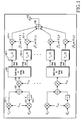
- FIG. 1 is a block diagram illustrating a transmitter to which the present invention is applied.
- a data symbol b k,n input to the transmitter is represented as b l k,n + jb Q k,n , and is the n-th data symbol of the k-th user.
- the input data symbol is multiplied by a PN code C k,q (0 ⁇ q ⁇ SF k , where SF k is the spreading factor of the k-th user) of the k-th user through multipliers 101-1 and 101-2.
- the imaginary part (jb Q k,n ) of the input data symbol is conjugated through a conjugation unit 102.
- the real part and the imaginary part (conjugated) of the input data symbol multiplied by the PN code are added together by an adder 103, and are then multiplied by the q-th chip S k,q of a scrambling code of the k-th user through a multiplier 104.
- the q-th chip S k,q of the scrambling code is represented as (S l k,q + iS Q k,q )/ 2 .
- the PN codes are used to differentiate the users in the same cell, and the scrambling codes are used to differentiate the different cells.
- the data symbol is split into a real part and an imaginary part through a splitter 105.
- the real part is multiplied by P 1 cos(2 f 1 t )
- the imaginary part is multiplied by - P 1 sin(2 f 1 t ) .
- P k and k f denote the transmission power and the carrier frequency of the k-th user, respectively.
- the created carriers are added together through an adder 108 and then transmitted through an antenna 109.
- respective variables b l k,n , b Q k,n , C k,q , S l k,q , and S Q k,q have a binary value (for example, +1 or -1).
- the PN codes are used to differentiate the users in the same cell, and the scrambling codes are used to differentiate the different cells.
- FIG. 2 is a block diagram illustrating an i-th receiver according to an embodiment of the present invention.
- the i-th receiver is constructed to correspond to the transmitter illustrated in FIG. 1.
- carriers are removed from the real part and the imaginary part of data received through an antenna 201 through multipliers 202-1 and 202-2, and the real part and the imaginary part of the data are processed in the unit of the chip duration T c,i of the i-th user through samplers and switches 203-1, 203-2, 204-1 and 204-2, and then added together through an adder 206.
- a decision variable Z i,n for the n-th data symbol of the i-th user is obtained by removing the scrambling code and the PN code from the data through multipliers 207 and 208.
- the received signal is filtered through MF ⁇ *T c,i (-t) for the chip waveform of the desired user before the sampling operation.
- the system according to the present invention has cells, each having K users, and there is no interference between the cells.
- AWGN Additional White Gaussian Noise
- Equation (1) denotes a data symbol to be transmitted to the desired user i, and is expressed by Equation (2).
- D i,n b i,n SF i P i
- Equation (3) the second term of the right side of the Equation (1) indicates the interference from other K-1 users in the cell, and respective I k,i,n is expressed by Equation (3).
- Equation (1) refers to AWGN, and is expressed by Equation (4).
- Equation (4) indicates AWGN in the receiver i having a two-sided spectral density of N 0 /2.
- Equation (4) are time convolutions of the PSF of the user k and the MF of the user i, respectively.
- ⁇ 1 (t) and ⁇ 2 (t) can be expressed by Equations (5) and (6), respectively.
- the cosine part of Equation (5) and the sine part of Equation (6) reflect the effect according to the carrier frequency separation between the users. Accordingly, if the carrier frequency separation exists, ⁇ 1 (t) and ⁇ 2 (t) do not become the RC function due to their sinusoidal parts. However, even if the carrier frequency separation does not exist and the sinusoidal parts in the Equations (5) and (6) are removed, the inconsistency of the chip duration of the PSF of the user k with the chip duration of the MF of the user i prevents ⁇ 1 (t) and ⁇ 2 (t) from becoming the RC function. Accordingly, in the receiver, the IUI (Inter User Interference) cannot be avoided due to the interference signal having the different chip transmission rate.
- IUI Inter User Interference
- E ⁇ is a statistical expected value.
- a closed-form solution to Var(I k,i,n ) is obtained by averaging the PN codes as shown in Equation (8).
- ⁇ 2 (0) is can be expressed as shown in Equation (10).
- ⁇ k(f) is the Fourier transform of ⁇ Tc,i (t). From the Equation (8), assuming that the chips C k,q are independently and individually distributed in the random variables, Parseval's theorem can be used.
- Equations (9) and (10) for ⁇ 1 (0) and ⁇ 2 (0) can easily be obtained using a mathematical integration because ⁇ k (f) is not "0" only in a limited frequency range. Unfortunately, it appears as if an efficient closed-form solution for the decided PN code is not possible. Also, in order to calculate the interference power, the Monte-Carlo simulation should be used.
- the interference caused by an OVSF (Orthogonal Variable Spreading Factor) codes is determined, and the determined interference is compared with the interference caused by the random codes.
- the index of the user having a low chip transmission rate is set to "1" and the index of the user having a high chip transmission rate is set to "2".
- the same system parameter as that used in a broad-band CDMA system for the 3 rd generation cellular system is selected.
- a system parameter having a chip transmission rate of 3.84 Mega chips/sec and an occupied bandwidth of 5 MHz may be used.
- g is the ratio of the chip transmission rates between the user of the high chip transmission rate and the user of the low chip transmission rate.
- k 1 and 2
- E s is a symbol energy.
- All the users use the same SF and the same RPC filter of a roll-off alpha factor of 0.22.
- the OVSF codes can be created using a code tree as illustrated in FIG. 3.
- the OVSF code is distinctively described by C ch,SF,j .
- SF and j denote the spreading factor and the code number (0 ⁇ j ⁇ SF-1) of the respective code.
- FIG. 3 illustrates a tree structure for generating OVSF codes used in a conventional CDMA communication system.
- a pattern in which an inverter is used with respect to each odd number and the original data is repeated with respect to each even number to match the SF is created.
- the corresponding SF and the channelization code are created by performing a bypass up to the necessary SF value or creating a continuous tree using an inverter.
- the PN codes of the users having the low chip transmission rate do not affect the interference power.
- the interference between the users having the different chip transmission rates only depends on the chip pattern of the users having the high chip transmission rate, which corresponds to one chip duration of the users having the low chip transmission rate.
- C ch,SF,j,m indicates the m-th chip of the PN code C ch,SF,j .
- FIG. 4 is a view illustrating a chip duration of users having a low chip transmission rate that is shorter than a bit duration of users having a high chip transmission rate (e.g., g ⁇ sf).
- the OVSF codes C ch,4,0 , C ch,4,1 have the same two-bit pattern "1, 1" or equivalently "-1, -1".
- the OVSF codes C ch,4,2 , C ch,4,3 have the same two-bit pattern "1, 1” or equivalently "-1, -1”.
- the OVSF codes C ch,4,0 , C ch,4,2 produce the same interference power curve as the OVSF codes C ch,4,1 , C ch,4,3 .
- FIG. 6 is a view illustrating a chip duration of a user having a low chip transmission rate that is longer than a bit duration of users having a high chip transmission rate (e.g., g>sf).
- all the OVSF codes of the users having the high chip transmission rate have a peculiar interference power curve.
- the chip duration of the PSF of the interferer is not equal to the chip duration of the MF of the desired user, the IUI is induced even if the carrier frequency separation is "0" as illustrated in FIGs. 4 and 5.
- the interference power is maintained over the whole area of the carrier frequency offset, and as the carrier frequency separation increases, the interference power decreases monotonically. This is because the interference power of the random code is in proportion to the spectral overlap between the interference signals as shown in the Equations (9) and (10).
- FIGs. 4, 5, and 6 illustrate that the average interference power of all the OVSF codes is equal to the average interference power of the random codes in a given carrier frequency separation. Accordingly, if all the OVSF codes of the users having the high chip transmission rate are used, their orthogonal PN codes show the same system performance as the random codes of the MCR direct-sequence CDMA system.
- the selection of proper PN codes for the users having the high chip transmission rate can reduce the interference power and increase the performance of the system.
- the chip waveforms of the users having the different transmission rates do not coincide with each other, even if the orthogonal PN codes are used in the MCR direct-sequence CDMA system, the signals having the different chip transmission rates interfere with each other.
- the IUI between the users having the different transmission rates has no relation to the OVSF codes of the users having the low transmission rate, but depends on the OVSF codes of the users having the high chip transmission rate.
- the OVSF codes for the relatively less interference power are allocated to the users having the high chip transmission rate, but there is no limit in selecting the OVSF codes for the users having the low chip transmission rate. Accordingly, the selection of the OVSF codes is beneficial when the number of users having the high chip transmission rate is smaller than the number of available OVSF codes.
- the IUI between the users having the different transmission rates is reduced by classifying the users in the cell of the MCR direct-sequence CDMA system according to the chip transmission rates, and giving the OVSF codes having speeds two times, four times, and eight time higher than those of the users having the low chip transmission rate with respect to the users having the high chip transmission rate. Consequently, the interference between the users can be reduced using the PN codes of the users having the high chip transmission rate which affect the interference between the users.
- the method according to the present invention can be implemented by a program, and stored in a recording medium such as a CD-ROM, RAM, floppy disc, hard disc, optomagnetic disc, etc.
Landscapes
- Engineering & Computer Science (AREA)
- Computer Networks & Wireless Communication (AREA)
- Signal Processing (AREA)
- Mobile Radio Communication Systems (AREA)
Abstract
Description


Claims (8)
- A method of selecting PN codes in a multiple chip rate direct-sequence CDMA system for reducing interference between users, comprising the steps of:assigning a chip transmission rate for each user in a cell of the multiple chip rate direct-sequence CDMA system; andselecting PN codes having a predetermined rate which is higher than that of PN codes of users having a low-speed chip transmission rate, with respect to users having a high chip transmission rate in accordance with the assigned chip transmission rate of the respective user.
- The method as claimed in claim 1, wherein the PN code having the predetermined rate is an orthogonal variable spreading factor code.
- The method as claimed in claim 1 or 2, wherein the predetermined rate is a ratio of chip transmission rates between users having the low chip transmission rate and the high chip transmission rate.
- The method as claimed in claim 3, wherein the predetermined rate is 2n with n being a positive integer number.
- An apparatus for selecting PN codes in a multiple chip rate direct-sequence CDMA system for reducing interference between users, wherein a chip transmission rate is assigned for each user in a cell of the multiple chip rate direct-sequence CDMA system, the apparatus comprising:means for selecting PN codes having a predetermined rate which is higher than that of PN codes of users having a low-speed chip transmission rate, with respect to users having a high chip transmission rate in accordance with the assigned chip transmission rate of the respective user.
- The apparatus as claimed in claim 5, wherein the PN code having the predetermined rate is an orthogonal variable spreading factor code.
- The apparatus as claimed in claim 5 or 6, wherein the predetermined rate is a ratio of chip transmission rates between users having the low chip transmission rate and the high chip transmission rate.
- The apparatus as claimed in claim 5, wherein the predetermined rate is 2n with n being a positive integer number.
Applications Claiming Priority (2)
| Application Number | Priority Date | Filing Date | Title |
|---|---|---|---|
| KR1020040025958A KR20050100549A (en) | 2004-04-14 | 2004-04-14 | Spreading code selecting method for reduce iui |
| KR2004025958 | 2004-04-14 |
Publications (2)
| Publication Number | Publication Date |
|---|---|
| EP1587232A2 true EP1587232A2 (en) | 2005-10-19 |
| EP1587232A3 EP1587232A3 (en) | 2006-03-29 |
Family
ID=34935177
Family Applications (1)
| Application Number | Title | Priority Date | Filing Date |
|---|---|---|---|
| EP05008187A Withdrawn EP1587232A3 (en) | 2004-04-14 | 2005-04-14 | Method of selecting PN codes for reducing interference between users and a method therefor |
Country Status (3)
| Country | Link |
|---|---|
| US (1) | US20050232337A1 (en) |
| EP (1) | EP1587232A3 (en) |
| KR (1) | KR20050100549A (en) |
Families Citing this family (1)
| Publication number | Priority date | Publication date | Assignee | Title |
|---|---|---|---|---|
| JP4805044B2 (en) * | 2006-07-14 | 2011-11-02 | 三星電子株式会社 | Wireless communication method in wireless communication system, base station apparatus and reception program thereof |
Family Cites Families (4)
| Publication number | Priority date | Publication date | Assignee | Title |
|---|---|---|---|---|
| US6563808B1 (en) * | 1998-03-04 | 2003-05-13 | Stanford Telecommunications, Inc. | Apparatus for incorporating multiple data rates in an orthogonal direct sequence code division multiple access (ODS-CDMA) communications system |
| US6885691B1 (en) * | 1999-08-02 | 2005-04-26 | Lg Information & Communications, Ltd. | Scrambling codes and channelization codes for multiple chip rate signals in CDMA cellular mobile radio communication system |
| US6552996B2 (en) * | 2001-09-18 | 2003-04-22 | Interdigital Communications Corporation | OVSF code system and methods |
| GB2381711B (en) * | 2001-10-31 | 2003-10-15 | Lucent Technologies Inc | A method of allocating a channelisation code to one of a plurality of user terminals, a code division multiple access telecommunications network, |
-
2004
- 2004-04-14 KR KR1020040025958A patent/KR20050100549A/en not_active Withdrawn
-
2005
- 2005-03-11 US US11/077,729 patent/US20050232337A1/en not_active Abandoned
- 2005-04-14 EP EP05008187A patent/EP1587232A3/en not_active Withdrawn
Also Published As
| Publication number | Publication date |
|---|---|
| US20050232337A1 (en) | 2005-10-20 |
| EP1587232A3 (en) | 2006-03-29 |
| KR20050100549A (en) | 2005-10-19 |
Similar Documents
| Publication | Publication Date | Title |
|---|---|---|
| US5237586A (en) | Rake receiver with selective ray combining | |
| EP0491668B1 (en) | CDMA subtractive demodulation | |
| JP3532556B2 (en) | High-speed data transmission wireless local area network | |
| CN1092460C (en) | Reception method and receiver | |
| AU6635696A (en) | Code acquisition in a cdma communication system using multiple walsh channels | |
| HK1009366B (en) | Cdma subtractive demodulation | |
| JP2002533008A (en) | Detection of random access channel preamble | |
| JP2006141031A (en) | Apparatus and method for performing preamble transmission and cell detection in an orthogonal frequency division multiple access system | |
| CN102780509A (en) | System, apparatus, and method for adaptive weighted interference cancellation using parallel residue compensation | |
| De Gaudenzi et al. | Signal recognition and signature code acquisition in CDMA mobile packet communications | |
| CN116319232B (en) | Satellite broadband and narrowband fusion access transmission method and device | |
| Yue | Spread spectrum mobile radio, 1977-1982 | |
| US6898176B1 (en) | Communications terminal and operating method | |
| Levitt et al. | Optimum detection of slow frequency-hopped signals | |
| EP1587232A2 (en) | Method of selecting PN codes for reducing interference between users and a method therefor | |
| US8958459B2 (en) | Method and apparatus for despread data in wireless communication system | |
| Hassan et al. | Perspectives in spread spectrum | |
| Lyu et al. | Spreading code selection for multiple chip rate DS-CDMA systems | |
| JPH07111495A (en) | Spread spectrum communication method, transmitter and receiver thereof | |
| Kumar et al. | OCDMA/OCDMA Overloading Scheme for Cellular DS-CDMA Using Orthogonal Gold Codes and Complex Scrambling. | |
| DaSilva et al. | Multicarrier orthogonal CDMA signals for quasi-synchronous communication systems | |
| KR100475037B1 (en) | DS/CDMA signature sequences based on PR-QMF coefficients | |
| Ueng et al. | Zero forcing and minimum mean square error equalization for OFDM-CDMA multiuser detection in multipath fading channels | |
| Nougarou et al. | Capacity Improvement of DS-CDMA Mobile Satellite Communication System Using the Adaptive Duplicated Filters and Interference Canceller | |
| Freiberg et al. | Equalisation in a multi-carrier code division multiple access multi-rate system |
Legal Events
| Date | Code | Title | Description |
|---|---|---|---|
| PUAI | Public reference made under article 153(3) epc to a published international application that has entered the european phase |
Free format text: ORIGINAL CODE: 0009012 |
|
| 17P | Request for examination filed |
Effective date: 20050414 |
|
| AK | Designated contracting states |
Kind code of ref document: A2 Designated state(s): AT BE BG CH CY CZ DE DK EE ES FI FR GB GR HU IE IS IT LI LT LU MC NL PL PT RO SE SI SK TR |
|
| AX | Request for extension of the european patent |
Extension state: AL BA HR LV MK YU |
|
| PUAL | Search report despatched |
Free format text: ORIGINAL CODE: 0009013 |
|
| AK | Designated contracting states |
Kind code of ref document: A3 Designated state(s): AT BE BG CH CY CZ DE DK EE ES FI FR GB GR HU IE IS IT LI LT LU MC NL PL PT RO SE SI SK TR |
|
| AX | Request for extension of the european patent |
Extension state: AL BA HR LV MK YU |
|
| RIC1 | Information provided on ipc code assigned before grant |
Ipc: H04B 1/707 20060101ALI20060208BHEP Ipc: H04J 11/00 20060101AFI20050712BHEP |
|
| 17Q | First examination report despatched |
Effective date: 20060928 |
|
| AKX | Designation fees paid |
Designated state(s): DE FR GB |
|
| RAP1 | Party data changed (applicant data changed or rights of an application transferred) |
Owner name: SAMSUNG ELECTRONICS CO., LTD. |
|
| STAA | Information on the status of an ep patent application or granted ep patent |
Free format text: STATUS: THE APPLICATION IS DEEMED TO BE WITHDRAWN |
|
| 18D | Application deemed to be withdrawn |
Effective date: 20160708 |