EP1587183A1 - An insert-molded article and a production method for insert-molded article - Google Patents
An insert-molded article and a production method for insert-molded article Download PDFInfo
- Publication number
- EP1587183A1 EP1587183A1 EP05007684A EP05007684A EP1587183A1 EP 1587183 A1 EP1587183 A1 EP 1587183A1 EP 05007684 A EP05007684 A EP 05007684A EP 05007684 A EP05007684 A EP 05007684A EP 1587183 A1 EP1587183 A1 EP 1587183A1
- Authority
- EP
- European Patent Office
- Prior art keywords
- insert
- casing
- mold
- interlocking portion
- molded article
- Prior art date
- Legal status (The legal status is an assumption and is not a legal conclusion. Google has not performed a legal analysis and makes no representation as to the accuracy of the status listed.)
- Granted
Links
Images



Classifications
-
- H—ELECTRICITY
- H01—ELECTRIC ELEMENTS
- H01R—ELECTRICALLY-CONDUCTIVE CONNECTIONS; STRUCTURAL ASSOCIATIONS OF A PLURALITY OF MUTUALLY-INSULATED ELECTRICAL CONNECTING ELEMENTS; COUPLING DEVICES; CURRENT COLLECTORS
- H01R43/00—Apparatus or processes specially adapted for manufacturing, assembling, maintaining, or repairing of line connectors or current collectors or for joining electric conductors
- H01R43/20—Apparatus or processes specially adapted for manufacturing, assembling, maintaining, or repairing of line connectors or current collectors or for joining electric conductors for assembling or disassembling contact members with insulating base, case or sleeve
- H01R43/24—Assembling by moulding on contact members
-
- B—PERFORMING OPERATIONS; TRANSPORTING
- B29—WORKING OF PLASTICS; WORKING OF SUBSTANCES IN A PLASTIC STATE IN GENERAL
- B29C—SHAPING OR JOINING OF PLASTICS; SHAPING OF MATERIAL IN A PLASTIC STATE, NOT OTHERWISE PROVIDED FOR; AFTER-TREATMENT OF THE SHAPED PRODUCTS, e.g. REPAIRING
- B29C45/00—Injection moulding, i.e. forcing the required volume of moulding material through a nozzle into a closed mould; Apparatus therefor
- B29C45/14—Injection moulding, i.e. forcing the required volume of moulding material through a nozzle into a closed mould; Apparatus therefor incorporating preformed parts or layers, e.g. injection moulding around inserts or for coating articles
- B29C45/14065—Positioning or centering articles in the mould
-
- B—PERFORMING OPERATIONS; TRANSPORTING
- B29—WORKING OF PLASTICS; WORKING OF SUBSTANCES IN A PLASTIC STATE IN GENERAL
- B29C—SHAPING OR JOINING OF PLASTICS; SHAPING OF MATERIAL IN A PLASTIC STATE, NOT OTHERWISE PROVIDED FOR; AFTER-TREATMENT OF THE SHAPED PRODUCTS, e.g. REPAIRING
- B29C45/00—Injection moulding, i.e. forcing the required volume of moulding material through a nozzle into a closed mould; Apparatus therefor
- B29C45/14—Injection moulding, i.e. forcing the required volume of moulding material through a nozzle into a closed mould; Apparatus therefor incorporating preformed parts or layers, e.g. injection moulding around inserts or for coating articles
- B29C45/14336—Coating a portion of the article, e.g. the edge of the article
- B29C45/14377—Coating a portion of the article, e.g. the edge of the article using an additional insert, e.g. a fastening element
-
- B—PERFORMING OPERATIONS; TRANSPORTING
- B29—WORKING OF PLASTICS; WORKING OF SUBSTANCES IN A PLASTIC STATE IN GENERAL
- B29C—SHAPING OR JOINING OF PLASTICS; SHAPING OF MATERIAL IN A PLASTIC STATE, NOT OTHERWISE PROVIDED FOR; AFTER-TREATMENT OF THE SHAPED PRODUCTS, e.g. REPAIRING
- B29C45/00—Injection moulding, i.e. forcing the required volume of moulding material through a nozzle into a closed mould; Apparatus therefor
- B29C45/14—Injection moulding, i.e. forcing the required volume of moulding material through a nozzle into a closed mould; Apparatus therefor incorporating preformed parts or layers, e.g. injection moulding around inserts or for coating articles
- B29C45/14639—Injection moulding, i.e. forcing the required volume of moulding material through a nozzle into a closed mould; Apparatus therefor incorporating preformed parts or layers, e.g. injection moulding around inserts or for coating articles for obtaining an insulating effect, e.g. for electrical components
-
- H—ELECTRICITY
- H05—ELECTRIC TECHNIQUES NOT OTHERWISE PROVIDED FOR
- H05K—PRINTED CIRCUITS; CASINGS OR CONSTRUCTIONAL DETAILS OF ELECTRIC APPARATUS; MANUFACTURE OF ASSEMBLAGES OF ELECTRICAL COMPONENTS
- H05K3/00—Apparatus or processes for manufacturing printed circuits
- H05K3/0058—Laminating printed circuit boards onto other substrates, e.g. metallic substrates
-
- B—PERFORMING OPERATIONS; TRANSPORTING
- B29—WORKING OF PLASTICS; WORKING OF SUBSTANCES IN A PLASTIC STATE IN GENERAL
- B29C—SHAPING OR JOINING OF PLASTICS; SHAPING OF MATERIAL IN A PLASTIC STATE, NOT OTHERWISE PROVIDED FOR; AFTER-TREATMENT OF THE SHAPED PRODUCTS, e.g. REPAIRING
- B29C45/00—Injection moulding, i.e. forcing the required volume of moulding material through a nozzle into a closed mould; Apparatus therefor
- B29C45/14—Injection moulding, i.e. forcing the required volume of moulding material through a nozzle into a closed mould; Apparatus therefor incorporating preformed parts or layers, e.g. injection moulding around inserts or for coating articles
- B29C45/14065—Positioning or centering articles in the mould
- B29C2045/14131—Positioning or centering articles in the mould using positioning or centering means forming part of the insert
-
- B—PERFORMING OPERATIONS; TRANSPORTING
- B29—WORKING OF PLASTICS; WORKING OF SUBSTANCES IN A PLASTIC STATE IN GENERAL
- B29C—SHAPING OR JOINING OF PLASTICS; SHAPING OF MATERIAL IN A PLASTIC STATE, NOT OTHERWISE PROVIDED FOR; AFTER-TREATMENT OF THE SHAPED PRODUCTS, e.g. REPAIRING
- B29C45/00—Injection moulding, i.e. forcing the required volume of moulding material through a nozzle into a closed mould; Apparatus therefor
- B29C45/16—Making multilayered or multicoloured articles
- B29C45/1671—Making multilayered or multicoloured articles with an insert
-
- H—ELECTRICITY
- H05—ELECTRIC TECHNIQUES NOT OTHERWISE PROVIDED FOR
- H05K—PRINTED CIRCUITS; CASINGS OR CONSTRUCTIONAL DETAILS OF ELECTRIC APPARATUS; MANUFACTURE OF ASSEMBLAGES OF ELECTRICAL COMPONENTS
- H05K2201/00—Indexing scheme relating to printed circuits covered by H05K1/00
- H05K2201/09—Shape and layout
- H05K2201/09009—Substrate related
- H05K2201/09118—Moulded substrate
-
- H—ELECTRICITY
- H05—ELECTRIC TECHNIQUES NOT OTHERWISE PROVIDED FOR
- H05K—PRINTED CIRCUITS; CASINGS OR CONSTRUCTIONAL DETAILS OF ELECTRIC APPARATUS; MANUFACTURE OF ASSEMBLAGES OF ELECTRICAL COMPONENTS
- H05K2203/00—Indexing scheme relating to apparatus or processes for manufacturing printed circuits covered by H05K3/00
- H05K2203/13—Moulding and encapsulation; Deposition techniques; Protective layers
- H05K2203/1305—Moulding and encapsulation
- H05K2203/1327—Moulding over PCB locally or completely
-
- H—ELECTRICITY
- H05—ELECTRIC TECHNIQUES NOT OTHERWISE PROVIDED FOR
- H05K—PRINTED CIRCUITS; CASINGS OR CONSTRUCTIONAL DETAILS OF ELECTRIC APPARATUS; MANUFACTURE OF ASSEMBLAGES OF ELECTRICAL COMPONENTS
- H05K3/00—Apparatus or processes for manufacturing printed circuits
- H05K3/10—Apparatus or processes for manufacturing printed circuits in which conductive material is applied to the insulating support in such a manner as to form the desired conductive pattern
- H05K3/20—Apparatus or processes for manufacturing printed circuits in which conductive material is applied to the insulating support in such a manner as to form the desired conductive pattern by affixing prefabricated conductor pattern
- H05K3/202—Apparatus or processes for manufacturing printed circuits in which conductive material is applied to the insulating support in such a manner as to form the desired conductive pattern by affixing prefabricated conductor pattern using self-supporting metal foil pattern
-
- Y—GENERAL TAGGING OF NEW TECHNOLOGICAL DEVELOPMENTS; GENERAL TAGGING OF CROSS-SECTIONAL TECHNOLOGIES SPANNING OVER SEVERAL SECTIONS OF THE IPC; TECHNICAL SUBJECTS COVERED BY FORMER USPC CROSS-REFERENCE ART COLLECTIONS [XRACs] AND DIGESTS
- Y10—TECHNICAL SUBJECTS COVERED BY FORMER USPC
- Y10T—TECHNICAL SUBJECTS COVERED BY FORMER US CLASSIFICATION
- Y10T428/00—Stock material or miscellaneous articles
- Y10T428/22—Nonparticulate element embedded or inlaid in substrate and visible
-
- Y—GENERAL TAGGING OF NEW TECHNOLOGICAL DEVELOPMENTS; GENERAL TAGGING OF CROSS-SECTIONAL TECHNOLOGIES SPANNING OVER SEVERAL SECTIONS OF THE IPC; TECHNICAL SUBJECTS COVERED BY FORMER USPC CROSS-REFERENCE ART COLLECTIONS [XRACs] AND DIGESTS
- Y10—TECHNICAL SUBJECTS COVERED BY FORMER USPC
- Y10T—TECHNICAL SUBJECTS COVERED BY FORMER US CLASSIFICATION
- Y10T428/00—Stock material or miscellaneous articles
- Y10T428/23—Sheet including cover or casing
-
- Y—GENERAL TAGGING OF NEW TECHNOLOGICAL DEVELOPMENTS; GENERAL TAGGING OF CROSS-SECTIONAL TECHNOLOGIES SPANNING OVER SEVERAL SECTIONS OF THE IPC; TECHNICAL SUBJECTS COVERED BY FORMER USPC CROSS-REFERENCE ART COLLECTIONS [XRACs] AND DIGESTS
- Y10—TECHNICAL SUBJECTS COVERED BY FORMER USPC
- Y10T—TECHNICAL SUBJECTS COVERED BY FORMER US CLASSIFICATION
- Y10T428/00—Stock material or miscellaneous articles
- Y10T428/24—Structurally defined web or sheet [e.g., overall dimension, etc.]
- Y10T428/24479—Structurally defined web or sheet [e.g., overall dimension, etc.] including variation in thickness
- Y10T428/24612—Composite web or sheet
Definitions
- the present invention relates to an insert-molded article and a production method for insert-molded article.
- the present invention was developed in view of the above problem and an object thereof is to improve operability, in particular ensure watertightness.
- an insert-molded article provided with a casing formed by insert molding using an inner portion holding at least one insert member, preferably at least one metal member, as an insert, wherein:
- the interlocking portion of the inner portion is hooked or interlocked or engaged in the mold for molding the casing, whereby the inner portion is so positioned and/or supported in or on the mold as to at least partly project from the inner wall surface of the mold, and insert molding is carried out in this state, thereby forming the casing in which the interlocking portion is located at the inner surface thereof and the inner portion substantially excluding the interlocking portion is at least partly covered by the resin portion.
- an end surface of the interlocking portion is not exposed at the outer surface of the casing. Therefore, the entrance of water from the outer surface of the casing can be advantageously prevented, and watertightness in the casing can be maintained.
- the interlocking portion is formed to project substantially toward the inside of the casing from the inner surface of the casing.
- interlocking portion is formed to project substantially toward the inside of the casing from the inner surface of the casing, insert molding can be carried out with the interlocking portion tightly held between an upper and a lower molds of the mold, thereby enabling the construction of the mold to be simplified.
- the insert (preferably metal) member includes at least one busbar electrically connectable with a conductor portion of a printed circuit board or an electrical or electronic component at least partly accommodated in the casing, and/or the interlocking portion is made of a synthetic resin material.
- the metal member is the electrically conductive busbar electrically connectable with the conductor portion of the printed circuit board or the electronic or electronic component accommodated in the casing and/or the interlocking portion is made of the synthetic resin, the busbar can be insulated to prevent an occurrence of a leakage.
- one of the interlocking portion and the mold comprise a recess and the other of the interlocking portion and the mold comprise a projection engageable with the recess.
- one or more recesses having substantially L-shaped cross sections are formed at one or more corner portions of the inner portion.
- two substantially L-shaped recesses are formed at a first corner and a second corner substantially diagonally opposite to the first corner of the inner portion.
- a production method for insert-molded article provided with a casing formed by insert molding using an inner portion holding at least one insert member as an insert comprising the following steps:
- a production method for insert-molded article provided with a casing formed by insert molding using an inner portion holding a metal member as an insert characterized in that:
- a recess provided at one of the interlocking portion and the mold is engaged with a projection provided at the other of the interlocking portion and the mold.
- the interlocking portion is tightly held between a first mold member and second mold member and/or at least partly projects in a cavity where molding material is at least partly filled.
- FIGS. 1 to 6 One preferred embodiment of the present invention is described with reference to FIGS. 1 to 6.
- An insert-molded article IMA according to this embodiment is one application of the present invention to an electronic control unit (ECU) having a printed circuit board at least partly accommodated inside a casing 10.
- FIG. 1 shows the entire casing 10.
- the casing 10 is made e.g. of a synthetic resin preferably substantially into a box having an open upper or lateral surface, and the printed circuit board is at least partly accommodated and a plurality of busbars are arranged therein.
- An unillustrated cover is or is to be mounted at or on an opening of the casing 10 to ensure watertightness in the casing 10.
- one or more mount holes 11 preferably in the form of through holes used to mount the casing 10 on a body of a vehicle are formed at specified (predetermined or predeterminable) positions at or on the outer periphery of the casing 10, and the casing 10 is to be mounted on the body by bolts inserted through these mount holes 11.
- One or more (preferably substantially strip-shaped) busbars or conductors 20 are at least partly embedded at specified (predetermined or predeterminable) parts of side walls 12 of the casing 10 along the wall surfaces of the side walls 12.
- the busbar 20 at least partly embedded in a bulging portion of the lateral (right) side wall 12 shown in FIG. 1 is crank-shaped and ends thereof at least partly project into the casing 10 to be connectable with the printed circuit board and electric or electronic components.
- an inner portion 30 having the one or more busbars 20 as inserts is used as an insert.
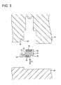
- the inner portion 30 is, as shown in FIG. 3, comprised of two busbars 20 spaced apart by a specified (predetermined or predeterminable) distance along thickness direction TD (or a direction substantially normal to the longitudinal direction of the busbars 20) and a holding portion 31 made e.g. of a synthetic resin for covering the facing surfaces of the respective busbars 20, wherein the respective busbars 20 are held at a specified (predetermined or predeterminable) spacing or distance by the holding portion 31.
- One or more recesses 32 having substantially L-shaped cross sections (or each opening to two lateral sides of the holding portion 31) are formed at a first (right lower) corner and a second (left upper) corner (substantially diagonally opposite to the first corner) of the holding portion 31 shown in FIG. 3.
- a resin portion 13 (to be described later) of the casing 10 at least partly enters these recesses 32 to enhance an engaging force with the resin portion 13, so that the inner portion 30 does not come out of the casing 10.
- An interlocking portion 33 made of a synthetic resin is so formed as to be substantially continuous with the holding portion 31 at the lateral (left) side of the busbar 20 disposed at a lower side in FIG. 3.
- the interlocking portion 33 is formed to substantially horizontally project from its base end toward its leading end, and can be hooked in a mold for secondary molding, and the inner portion 30 is so positioned and supported in the mold 61 as to project from the inner wall surface of the mold 61 by the engagement of the interlocking portion 33 and the mold 61.
- a recess 34 is formed at the base end or extending portion of the interlocking portion 33, and the inner portion 30 is prevented from lateral loose movements by the engagement of this recess 34 and a projection 63 formed in the mold 61.
- the recess 34 is so formed in the lateral (upper) surface of the interlocking portion 33 as to be open upward or laterally and have a substantially U-shaped cross section, and is closely engageable with the projection 63.
- the casing 10 is formed by insert molding using the above inner portion 30 as an insert such that the inner portion 30 excluding the interlocking portion 33 is at least partly, preferably substantially completely covered by the resin portion 13 (made of the preferably same synthetic resin as the holding portion 31).
- the interlocking portion 33 is located at the inner surface of the casing 10 and projects toward the inside of the casing 10 from the inner surface of the casing 10 with the recess 34 as a border.
- This mold is comprised of a lower mold 60 and an upper mold 61 as shown in FIG. 3.
- the upper mold 61 is provided with a receiving portion 62 recessed substantially in conformity with the shape of the interlocking portion 33, and the aforementioned projection 63 is provided on the inner wall surface of this receiving portion 62 to project downward or laterally.
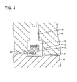
- the interlocking portion 33 is engageable with the receiving portion 62 as the mold 61, 62 is closed. As being engaged with the receiving portion 62, the interlocking portion 33 is tightly held between the upper mold 61 and the lower mold 60 and projects in a cavity 66.
- the inner portion 30 is formed by insert molding using the one or more busbars 20 as inserts. Subsequently, as shown in FIGS. 3 and 4, the lower and upper molds 60, 61 are brought to the inner portion 30, thereby closing the mold to at least partly fit the interlocking portion 33 in the receiving portion 62. As the mold closing is completed, the interlocking portion 33 is tightly held between the upper and lower molds 61, 60 and the recess 34 of the interlocking portion 33 and the projection 63 of the upper mold 61 are engaged with each other, with the result that the inner portion 30 is so positioned and supported as to project from the inner wall surface of the mold while being prevented from lateral and vertical loose movements.
- Molten resin is injected to at least partly fill the cavity 66 of the mold in this state.
- the substantially entire casing 10 including a side wall portion shown in FIG. 6 is obtained.
- the casing 10 as a finished article is such that the interlocking portion 33 is exposed at the inner surface thereof and the holding portion 31 is preferably substantially entirely covered by the resin portion 13.
- the interlocking portion 33 is hooked in or interlocked with the mold to thereby position and support the inner portion 30 in the mold in such a manner as to project from the inner wall surface of the mold during the insert molding using the inner portion 30 as an insert.
- the preferably substantially entire inner portion 30 excluding the interlocking portion 33 can be covered by the resin portion 13.
- the interlocking portion 33 is formed to project toward the inside of the casing 10 from the inner surface of the casing 10, insert molding can be carried out with the interlocking portion 33 tightly held between the upper and lower molds 61, 60. Therefore, the construction of the mold can be simplified.
- a casing 10 is formed by insert molding using an inner portion 30 holding one or more busbars or conductors 20 as an insert.
- the inner portion 30 includes an interlocking portion 33 to be hooked in a mold for molding the casing 10, and is so positioned and supported in the mold by the presence of the interlocking portion 33 as to project from the inner wall surface of the mold.
- the interlocking portion 33 is formed to project substantially toward the inside of the casing 10 from the inner surface of the casing 10.
- the casing 10 is formed by at least partly covering the inner portion 30 substantially excluding the interlocking portion 33 by a resin portion 13.
Landscapes
- Engineering & Computer Science (AREA)
- Manufacturing & Machinery (AREA)
- Mechanical Engineering (AREA)
- Microelectronics & Electronic Packaging (AREA)
- Injection Moulding Of Plastics Or The Like (AREA)
- Moulds For Moulding Plastics Or The Like (AREA)
- Casings For Electric Apparatus (AREA)
Abstract
Description
- The present invention relates to an insert-molded article and a production method for insert-molded article.
- There has been known a technology of forming a primary molded article using an electrically conductive member made of a metal as an insert and then forming a secondary molded article using the primary molded article as an insert (for example, see Japanese Unexamined Patent Publication No. H09-300401). According to this technology, there is a merit of being able to precisely position the electrically conductive member in a mold for the secondary molding since the primary molded article can be set in the mold with a supporting portion formed during the primary molding held in contact with the inner wall surface of the mold.
- In the above case, an end surface of the supporting portion of the primary molded article is exposed at the outer surface of the secondary molded article after the insert molding. Thus, there is a possibility that moisture enters a tiny clearance created at an interface of the primary molded article and the secondary molded article from the periphery of the end surface of the supporting portion. Particularly in an ECU casing having a printed circuit board accommodated therein or the like, there has been a problem of being unable to maintain watertightness in the casing due to the water entrance from the exposed end surface if the end surface of the supporting portion is exposed at the outer surface of the casing.
- The present invention was developed in view of the above problem and an object thereof is to improve operability, in particular ensure watertightness.
- This object is solved according to the invention by the features of the independent claims. Preferred embodiments of the invention are subject of the dependent claims.
- According to the invention, there is provided an insert-molded article provided with a casing formed by insert molding using an inner portion holding at least one insert member, preferably at least one metal member, as an insert, wherein:
- the inner portion includes at least one interlocking portion to be hooked or interlocked or engaged in a mold for molding the casing and is so positioned and supported in the mold by the presence of the interlocking portion as to at least partly project from an inner wall surface of the mold,
- the interlocking portion is located at or on the inner surface of the casing, and
- the casing is formed by at least partly covering the inner portion substantially excluding the interlocking portion by a resin portion.
-
- The interlocking portion of the inner portion is hooked or interlocked or engaged in the mold for molding the casing, whereby the inner portion is so positioned and/or supported in or on the mold as to at least partly project from the inner wall surface of the mold, and insert molding is carried out in this state, thereby forming the casing in which the interlocking portion is located at the inner surface thereof and the inner portion substantially excluding the interlocking portion is at least partly covered by the resin portion. Thus, an end surface of the interlocking portion is not exposed at the outer surface of the casing. Therefore, the entrance of water from the outer surface of the casing can be advantageously prevented, and watertightness in the casing can be maintained.
- According to a preferred embodiment of the invention, the interlocking portion is formed to project substantially toward the inside of the casing from the inner surface of the casing.
- Since the interlocking portion is formed to project substantially toward the inside of the casing from the inner surface of the casing, insert molding can be carried out with the interlocking portion tightly held between an upper and a lower molds of the mold, thereby enabling the construction of the mold to be simplified.
- Preferably, the insert (preferably metal) member includes at least one busbar electrically connectable with a conductor portion of a printed circuit board or an electrical or electronic component at least partly accommodated in the casing, and/or the interlocking portion is made of a synthetic resin material.
- Since the metal member is the electrically conductive busbar electrically connectable with the conductor portion of the printed circuit board or the electronic or electronic component accommodated in the casing and/or the interlocking portion is made of the synthetic resin, the busbar can be insulated to prevent an occurrence of a leakage.
- Further preferably, one of the interlocking portion and the mold comprise a recess and the other of the interlocking portion and the mold comprise a projection engageable with the recess.
- Still further preferably, one or more recesses having substantially L-shaped cross sections are formed at one or more corner portions of the inner portion.
- Most preferably, two substantially L-shaped recesses are formed at a first corner and a second corner substantially diagonally opposite to the first corner of the inner portion.
- According to the invention, there is further provided a production method for insert-molded article provided with a casing formed by insert molding using an inner portion holding at least one insert member as an insert, comprising the following steps:
- hooking an interlocking portion provided at the inner portion in a mold for molding the casing, whereby positioning and supporting the inner portion so in the mold as to project from an inner wall surface of the mold, and
- carrying out insert molding in this state, thereby forming the casing in which the interlocking portion is located at the inner surface thereof and the inner portion substantially excluding the interlocking portion is at least partly covered by a resin portion.
-
- According to a preferred embodiment of the invention, there is provided a production method for insert-molded article provided with a casing formed by insert molding using an inner portion holding a metal member as an insert, characterized in that:
- an interlocking portion provided at the inner portion is hooked in a mold for molding the casing, whereby the inner portion is so positioned and supported in the mold as to project from an inner wall surface of the mold, and
- insert molding is carried out in this state, thereby forming the casing in which the interlocking portion is located at the inner surface thereof and the inner portion excluding the interlocking portion is covered by a resin portion.
-
- Preferably, in the hooking step a recess provided at one of the interlocking portion and the mold is engaged with a projection provided at the other of the interlocking portion and the mold.
- Most preferably, in or during the insert molding step the interlocking portion is tightly held between a first mold member and second mold member and/or at least partly projects in a cavity where molding material is at least partly filled.
- These and other objects, features and advantages of the present invention will become more apparent upon reading of the following detailed description of preferred embodiments and accompanying drawings. It should be understood that even though embodiments are separately described, single features thereof may be combined to additional embodiments.
- FIG. 1 is a plan view of an ECU casing according to one embodiment of the invention,
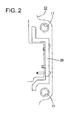
- FIG. 2 is an enlarged plan view showing an essential portion of an embedded state of a busbar,
- FIG. 3 is a section showing a state before an inner portion is set in a mold,
- FIG. 4 is a section showing a state where the inner portion is set in the mold,
- FIG. 5 is a section showing a state where molten resin is filled into a cavity, and
- FIG. 6 is a section showing a state where the mold is opened to enable the inner portion to be taken out.
-
- One preferred embodiment of the present invention is described with reference to FIGS. 1 to 6. An insert-molded article IMA according to this embodiment is one application of the present invention to an electronic control unit (ECU) having a printed circuit board at least partly accommodated inside a
casing 10. FIG. 1 shows theentire casing 10. - The
casing 10 is made e.g. of a synthetic resin preferably substantially into a box having an open upper or lateral surface, and the printed circuit board is at least partly accommodated and a plurality of busbars are arranged therein. - An unillustrated cover is or is to be mounted at or on an opening of the
casing 10 to ensure watertightness in thecasing 10. Further, one ormore mount holes 11 preferably in the form of through holes used to mount thecasing 10 on a body of a vehicle are formed at specified (predetermined or predeterminable) positions at or on the outer periphery of thecasing 10, and thecasing 10 is to be mounted on the body by bolts inserted through thesemount holes 11. - One or more (preferably substantially strip-shaped) busbars or
conductors 20 are at least partly embedded at specified (predetermined or predeterminable) parts ofside walls 12 of thecasing 10 along the wall surfaces of theside walls 12. Thebusbar 20 at least partly embedded in a bulging portion of the lateral (right)side wall 12 shown in FIG. 1 is crank-shaped and ends thereof at least partly project into thecasing 10 to be connectable with the printed circuit board and electric or electronic components. Upon molding such a portion, aninner portion 30 having the one ormore busbars 20 as inserts is used as an insert. - The
inner portion 30 is, as shown in FIG. 3, comprised of twobusbars 20 spaced apart by a specified (predetermined or predeterminable) distance along thickness direction TD (or a direction substantially normal to the longitudinal direction of the busbars 20) and aholding portion 31 made e.g. of a synthetic resin for covering the facing surfaces of therespective busbars 20, wherein therespective busbars 20 are held at a specified (predetermined or predeterminable) spacing or distance by theholding portion 31. One ormore recesses 32 having substantially L-shaped cross sections (or each opening to two lateral sides of the holding portion 31) are formed at a first (right lower) corner and a second (left upper) corner (substantially diagonally opposite to the first corner) of theholding portion 31 shown in FIG. 3. A resin portion 13 (to be described later) of thecasing 10 at least partly enters theserecesses 32 to enhance an engaging force with theresin portion 13, so that theinner portion 30 does not come out of thecasing 10. An interlockingportion 33 made of a synthetic resin is so formed as to be substantially continuous with theholding portion 31 at the lateral (left) side of thebusbar 20 disposed at a lower side in FIG. 3. - The interlocking
portion 33 is formed to substantially horizontally project from its base end toward its leading end, and can be hooked in a mold for secondary molding, and theinner portion 30 is so positioned and supported in themold 61 as to project from the inner wall surface of themold 61 by the engagement of the interlockingportion 33 and themold 61. Arecess 34 is formed at the base end or extending portion of the interlockingportion 33, and theinner portion 30 is prevented from lateral loose movements by the engagement of thisrecess 34 and aprojection 63 formed in themold 61. In other words, therecess 34 is so formed in the lateral (upper) surface of the interlockingportion 33 as to be open upward or laterally and have a substantially U-shaped cross section, and is closely engageable with theprojection 63. - The
casing 10 is formed by insert molding using the aboveinner portion 30 as an insert such that theinner portion 30 excluding the interlockingportion 33 is at least partly, preferably substantially completely covered by the resin portion 13 (made of the preferably same synthetic resin as the holding portion 31). Here, the interlockingportion 33 is located at the inner surface of thecasing 10 and projects toward the inside of thecasing 10 from the inner surface of thecasing 10 with therecess 34 as a border. - Next, the construction of the mold for secondary molding is described. This mold is comprised of a
lower mold 60 and anupper mold 61 as shown in FIG. 3. Theupper mold 61 is provided with a receivingportion 62 recessed substantially in conformity with the shape of the interlockingportion 33, and theaforementioned projection 63 is provided on the inner wall surface of this receivingportion 62 to project downward or laterally. The interlockingportion 33 is engageable with thereceiving portion 62 as themold receiving portion 62, the interlockingportion 33 is tightly held between theupper mold 61 and thelower mold 60 and projects in acavity 66. - Next, a method for producing the
casing 10 according to this embodiment is described. First, theinner portion 30 is formed by insert molding using the one ormore busbars 20 as inserts. Subsequently, as shown in FIGS. 3 and 4, the lower andupper molds inner portion 30, thereby closing the mold to at least partly fit the interlockingportion 33 in the receivingportion 62. As the mold closing is completed, the interlockingportion 33 is tightly held between the upper andlower molds recess 34 of the interlockingportion 33 and theprojection 63 of theupper mold 61 are engaged with each other, with the result that theinner portion 30 is so positioned and supported as to project from the inner wall surface of the mold while being prevented from lateral and vertical loose movements. Molten resin is injected to at least partly fill thecavity 66 of the mold in this state. When the molten resin is cooled and solidified or cured and the mold is opened, the substantiallyentire casing 10 including a side wall portion shown in FIG. 6 is obtained. Thecasing 10 as a finished article is such that the interlockingportion 33 is exposed at the inner surface thereof and the holdingportion 31 is preferably substantially entirely covered by theresin portion 13. - As described above, according to this embodiment, the interlocking
portion 33 is hooked in or interlocked with the mold to thereby position and support theinner portion 30 in the mold in such a manner as to project from the inner wall surface of the mold during the insert molding using theinner portion 30 as an insert. Thus, the preferably substantially entireinner portion 30 excluding the interlockingportion 33 can be covered by theresin portion 13. At this time, since the interlockingportion 33 is located at the inner surface of thecasing 10, an end surface or the like of the interlockingportion 33 is not exposed at the outer surface of thecasing 10, wherefore the entrance of water from the outside of thecasing 10 can be securely prevented. As a result, watertightness in thecasing 10 can be maintained. Further, an occurrence of a leakage can be prevented. - Further, since the interlocking
portion 33 is formed to project toward the inside of thecasing 10 from the inner surface of thecasing 10, insert molding can be carried out with the interlockingportion 33 tightly held between the upper andlower molds - Accordingly, to ensure or enhance watertightness in a casing, a
casing 10 is formed by insert molding using aninner portion 30 holding one or more busbars orconductors 20 as an insert. Theinner portion 30 includes an interlockingportion 33 to be hooked in a mold for molding thecasing 10, and is so positioned and supported in the mold by the presence of the interlockingportion 33 as to project from the inner wall surface of the mold. The interlockingportion 33 is formed to project substantially toward the inside of thecasing 10 from the inner surface of thecasing 10. Thecasing 10 is formed by at least partly covering theinner portion 30 substantially excluding the interlockingportion 33 by aresin portion 13. - The present invention is not limited to the above described and illustrated embodiment. For example, the following embodiments are also embraced by the technical scope of the present invention as defined by the claims. Beside the following embodiments, various changes can be made without departing from the scope and spirit of the present invention as defined by the claims.
- (1) Although the inner portion is formed by insert molding using the one or more busbars as inserts in the foregoing embodiment, the inner portion may be comprised of one or more busbars and a cover capable of holding the busbar(s) without being insert-molded according to the present invention.
- (2) Although the interlocking portion is formed to project toward the inside of the casing in the foregoing embodiment, it is sufficient for the interlocking portion to be located at the inner surface of the casing so as to be hookable or interlockable in the mold according to the present invention. For example, the interlocking portion may be formed to retract into the side wall of the casing.
- (3) Although the interlocking portion is made of the synthetic resin in the foregoing embodiment, it may be formed by a part of the busbar according to the present invention. Then, the busbar and a conductor arranged in the casing can be electrically connected by causing the busbar as the interlocking portion to project toward the inside of the casing.
- (4) Although the inner portion holds the busbars in the foregoing embodiment, the inner portion may hold mere metal member(s) other than the busbars according to the present invention.
- (5) Although in the above embodiment only one interlocking
portion 33 is provided, it should be understood that two or more interlocking portions may be provided for correctly positioning or holding the inner portion during the molding process. -
-
- 10
- casing
- 13
- resin portion
- 20
- busbar
- 30
- inner portion
- 33
- interlocking portion
- 60
- lower mold
- 61
- upper mold
- 62
- receiving portion
Claims (10)
- An insert-molded article (IMA) provided with a casing (10) formed by insert molding using an inner portion (30) holding at least one insert member (20) as an insert, wherein:the inner portion (30) includes at least one interlocking portion (33) to be hooked in a mold (60, 61) for molding the casing (10) and is so positioned and supported in the mold (60, 61) by the presence of the interlocking portion (33) as to project from an inner wall surface of the mold (60, 61),the interlocking portion (33) is located at the inner surface of the casing (10), andthe casing (10) is formed by at least partly covering the inner portion (30) substantially excluding the interlocking portion (33) by a resin portion.
- An insert-molded article according to claim 1, wherein the interlocking portion (33) is formed to project substantially toward the inside of the casing (10) from the inner surface of the casing (10).
- An insert-molded article according to one or more of the preceding claims, wherein the insert member (20) includes a busbar (20) electrically connectable with a conductor portion of a printed circuit board or an electrical or electronic component at least partly accommodated in the casing (10).
- An insert-molded article according to one or more of the preceding claims, wherein the interlocking portion (33) is made of a synthetic resin material.
- An insert-molded article according to one or more of the preceding claims, wherein one of the interlocking portion (33) and the mold (60, 61) comprise a recess (34) and the other of the interlocking portion (33) and the mold (60, 61) comprise a projection (63) engageable with the recess (34).
- An insert-molded article according to one or more of the preceding claims, wherein one or more recesses (32) having substantially L-shaped cross sections are formed at one or more corner portions of the inner portion (30).
- An insert-molded article according to claim 6, wherein two substantially L-shaped recesses (32) are formed at a first corner and a second corner substantially diagonally opposite to the first corner of the inner portion (30).
- A production method for insert-molded article (IMA) provided with a casing (10) formed by insert molding using an inner portion (30) holding at least one insert member (20) as an insert, comprising the following steps:hooking an interlocking portion (33) provided at the inner portion (30) in a mold (60, 61) for molding the casing (10), whereby positioning and supporting the inner portion (30) so in the mold (60, 61) as to project from an inner wall surface of the mold (60, 61), andcarrying out insert molding in this state, thereby forming the casing (10) in which the interlocking portion (33) is located at the inner surface thereof and the inner portion (30) substantially excluding the interlocking portion (33) is at least partly covered by a resin portion.
- A method according to claim 8, wherein in the hooking step a recess (34) provided at one of the interlocking portion (33) and the mold (60, 61) is engaged with a projection (63) provided at the other of the interlocking portion (33) and the mold (60, 61).
- A method according to claim 8 or 9, wherein in or during the insert molding step the interlocking portion (33) is tightly held between a first mold member (60) and second mold member (61) and/or at least partly projects in a cavity (66)
where molding material is at least partly filled.
Applications Claiming Priority (2)
| Application Number | Priority Date | Filing Date | Title |
|---|---|---|---|
| JP2004117838A JP4189753B2 (en) | 2004-04-13 | 2004-04-13 | Insert molded product and method of manufacturing insert molded product |
| JP2004117838 | 2004-04-13 |
Publications (2)
| Publication Number | Publication Date |
|---|---|
| EP1587183A1 true EP1587183A1 (en) | 2005-10-19 |
| EP1587183B1 EP1587183B1 (en) | 2008-08-27 |
Family
ID=34934880
Family Applications (1)
| Application Number | Title | Priority Date | Filing Date |
|---|---|---|---|
| EP05007684A Expired - Lifetime EP1587183B1 (en) | 2004-04-13 | 2005-04-07 | An insert-molded article and a production method for insert-molded article |
Country Status (5)
| Country | Link |
|---|---|
| US (1) | US7560153B2 (en) |
| EP (1) | EP1587183B1 (en) |
| JP (1) | JP4189753B2 (en) |
| CN (1) | CN100417508C (en) |
| DE (1) | DE602005009276D1 (en) |
Cited By (4)
| Publication number | Priority date | Publication date | Assignee | Title |
|---|---|---|---|---|
| WO2008043691A1 (en) * | 2006-10-10 | 2008-04-17 | Robert Bosch Gmbh | Injection-moulded plastic component with insert |
| EP2500985A1 (en) * | 2011-03-15 | 2012-09-19 | Sumitomo Wiring Systems, Ltd. | Device connector and production method therefor |
| EP3093116A1 (en) * | 2015-05-13 | 2016-11-16 | Stefan Pfaff Werkzeug- und Formenbau GmbH & Co. KG | Method of making and positioning sealing sections |
| WO2017042346A1 (en) * | 2015-09-10 | 2017-03-16 | Stefan Pfaff Werkzeug- Und Formenbau Gmbh & Co. Kg | Production and positioning method for sealing profiles |
Families Citing this family (20)
| Publication number | Priority date | Publication date | Assignee | Title |
|---|---|---|---|---|
| JP4679327B2 (en) | 2005-10-12 | 2011-04-27 | 株式会社リコー | Image forming apparatus |
| JP4720648B2 (en) * | 2006-06-29 | 2011-07-13 | 住友電装株式会社 | Manufacturing method of resin molded products |
| JP2010105337A (en) * | 2008-10-31 | 2010-05-13 | Nissha Printing Co Ltd | Insert two-color molding method, two-color molding mold apparatus, and insert two-color molding |
| JP5509737B2 (en) * | 2009-03-25 | 2014-06-04 | アイシン精機株式会社 | Solenoid valve mounting structure |
| KR101101491B1 (en) * | 2010-02-25 | 2012-01-03 | 삼성전기주식회사 | Antenna pattern frame, electronic device case and manufacturing mold thereof |
| KR101053336B1 (en) * | 2010-03-15 | 2011-08-01 | 삼성전기주식회사 | Antenna pattern frame, electronic device case and manufacturing mold thereof |
| JP5626047B2 (en) * | 2011-03-15 | 2014-11-19 | 住友電装株式会社 | Connector for equipment |
| JP5846802B2 (en) * | 2011-08-11 | 2016-01-20 | 矢崎総業株式会社 | Connector and method of manufacturing the connector |
| JP5661087B2 (en) * | 2012-11-30 | 2015-01-28 | 東海興業株式会社 | Insert molded product, insert molding method, and insert molding apparatus |
| JP6155057B2 (en) * | 2013-03-08 | 2017-06-28 | Kyb株式会社 | Busbar unit manufacturing method and busbar unit |
| JP6610413B2 (en) * | 2016-04-26 | 2019-11-27 | 中西金属工業株式会社 | Manufacturing method of insert molded product |
| JP6605417B2 (en) * | 2016-08-31 | 2019-11-13 | 東海興業株式会社 | Resin molded product and manufacturing method thereof |
| FR3059202B1 (en) * | 2016-11-18 | 2019-08-16 | Continental Automotive France | METHOD OF MANUFACTURING ON A PLATE FOR MAINTAINING AN ELECTRONIC MODULE WITH POSITIONING FORMS EXCEEDING FINAL OVER-MOLDING |
| ES2766768T3 (en) * | 2017-04-10 | 2020-06-15 | Gemue Gebr Mueller Appbau Gmbh & Co Kg | Method of manufacturing an elastomeric membrane |
| US10768358B2 (en) * | 2017-08-17 | 2020-09-08 | Dura Operating, Llc | Printed film with mounted light emitting diodes encapsulated in light guide |
| JP7317471B2 (en) * | 2018-04-17 | 2023-07-31 | 本田技研工業株式会社 | molded body and mold |
| CN109016328A (en) * | 2018-05-29 | 2018-12-18 | 广东联塑科技实业有限公司 | A kind of preparation method with steel skeleton PE valve body |
| JP7077928B2 (en) * | 2018-12-06 | 2022-05-31 | 住友電装株式会社 | Connector and its manufacturing method |
| JP7007512B1 (en) * | 2021-05-31 | 2022-02-10 | 株式会社アテックス | Conductive member and its manufacturing method |
| JP7544780B2 (en) | 2022-10-04 | 2024-09-03 | 矢崎総業株式会社 | Plastic moldings |
Citations (3)
| Publication number | Priority date | Publication date | Assignee | Title |
|---|---|---|---|---|
| DE19504828A1 (en) * | 1995-02-14 | 1996-08-22 | Fritz Richard Gmbh & Co Kg | Bonding a frame to glass leaving free edge esp. for automobile glazing |
| US6294851B1 (en) * | 1998-06-10 | 2001-09-25 | Asmo Co., Ltd. | Resin molding method for inserting terminal and connector for motor having the terminal |
| US20040002260A1 (en) * | 2002-06-28 | 2004-01-01 | Sumitomo Wiring Systems, Ltd. | Insert-molded connector and method of forming it |
Family Cites Families (3)
| Publication number | Priority date | Publication date | Assignee | Title |
|---|---|---|---|---|
| CN2030764U (en) * | 1987-07-14 | 1989-01-11 | 施吾铨 | Plug with fuse |
| JP3870467B2 (en) * | 1996-03-12 | 2007-01-17 | 株式会社デンソー | Molded product having electrical connection and molding method thereof |
| CN2296079Y (en) * | 1997-11-05 | 1998-10-28 | 中国航天工业总公司第二研究院二○三所 | Universal power socket |
-
2004
- 2004-04-13 JP JP2004117838A patent/JP4189753B2/en not_active Expired - Lifetime
-
2005
- 2005-04-07 EP EP05007684A patent/EP1587183B1/en not_active Expired - Lifetime
- 2005-04-07 DE DE602005009276T patent/DE602005009276D1/en not_active Expired - Lifetime
- 2005-04-11 US US11/103,833 patent/US7560153B2/en active Active
- 2005-04-13 CN CNB2005100649978A patent/CN100417508C/en not_active Expired - Lifetime
Patent Citations (3)
| Publication number | Priority date | Publication date | Assignee | Title |
|---|---|---|---|---|
| DE19504828A1 (en) * | 1995-02-14 | 1996-08-22 | Fritz Richard Gmbh & Co Kg | Bonding a frame to glass leaving free edge esp. for automobile glazing |
| US6294851B1 (en) * | 1998-06-10 | 2001-09-25 | Asmo Co., Ltd. | Resin molding method for inserting terminal and connector for motor having the terminal |
| US20040002260A1 (en) * | 2002-06-28 | 2004-01-01 | Sumitomo Wiring Systems, Ltd. | Insert-molded connector and method of forming it |
Cited By (4)
| Publication number | Priority date | Publication date | Assignee | Title |
|---|---|---|---|---|
| WO2008043691A1 (en) * | 2006-10-10 | 2008-04-17 | Robert Bosch Gmbh | Injection-moulded plastic component with insert |
| EP2500985A1 (en) * | 2011-03-15 | 2012-09-19 | Sumitomo Wiring Systems, Ltd. | Device connector and production method therefor |
| EP3093116A1 (en) * | 2015-05-13 | 2016-11-16 | Stefan Pfaff Werkzeug- und Formenbau GmbH & Co. KG | Method of making and positioning sealing sections |
| WO2017042346A1 (en) * | 2015-09-10 | 2017-03-16 | Stefan Pfaff Werkzeug- Und Formenbau Gmbh & Co. Kg | Production and positioning method for sealing profiles |
Also Published As
| Publication number | Publication date |
|---|---|
| EP1587183B1 (en) | 2008-08-27 |
| DE602005009276D1 (en) | 2008-10-09 |
| JP4189753B2 (en) | 2008-12-03 |
| CN1683140A (en) | 2005-10-19 |
| US7560153B2 (en) | 2009-07-14 |
| CN100417508C (en) | 2008-09-10 |
| US20050227036A1 (en) | 2005-10-13 |
| JP2005297387A (en) | 2005-10-27 |
Similar Documents
| Publication | Publication Date | Title |
|---|---|---|
| EP1587183B1 (en) | An insert-molded article and a production method for insert-molded article | |
| EP2500995B1 (en) | Production method for a connector | |
| EP2500997B1 (en) | Connector and method of producing it | |
| EP2500985B1 (en) | Device connector and production method therefor | |
| EP1810810B1 (en) | Moulding construction and a molding method of a resin-molded product | |
| EP0853356B1 (en) | A connector producing method and a connector produced by insert molding and a use thereof | |
| JP7850379B2 (en) | Fuse unit and manufacturing method of fuse unit | |
| JPH04263913A (en) | Resin insertion molding method of metallic material | |
| JP6798436B2 (en) | Circuit equipment, circuit equipment manufacturing methods, and connectors | |
| EP2234222A1 (en) | Shield connector and production method therefor | |
| JP2005288763A (en) | Method for producing insert-molded article | |
| US6045739A (en) | Method of manufacturing a molded product internally having inserts in a layered state | |
| JP3287532B2 (en) | Insert molding method | |
| JP7077928B2 (en) | Connector and its manufacturing method | |
| US20120258619A1 (en) | Connector and electrical connection box | |
| US6203358B1 (en) | Electrical connection box and a method for manufacturing such an electrical connection box | |
| JP7099290B2 (en) | Reactor manufacturing method | |
| JP2006315280A (en) | Molded structure of case with connector | |
| JP2006281622A (en) | Double resin injection molding method, resin product molded by the method, and regulator case for alternator | |
| JP4863954B2 (en) | Electronic unit and manufacturing method thereof | |
| CN109891681A (en) | Connector with a locking member | |
| JP5526806B2 (en) | Circuit structure, method for manufacturing circuit structure, and electrical junction box | |
| JP6962899B2 (en) | Electronic components and manufacturing methods for electronic components | |
| JP2005295628A (en) | Insert molded product | |
| KR20240058794A (en) | Waterproof electromagnetic device and production method thereof |
Legal Events
| Date | Code | Title | Description |
|---|---|---|---|
| PUAI | Public reference made under article 153(3) epc to a published international application that has entered the european phase |
Free format text: ORIGINAL CODE: 0009012 |
|
| 17P | Request for examination filed |
Effective date: 20050414 |
|
| AK | Designated contracting states |
Kind code of ref document: A1 Designated state(s): AT BE BG CH CY CZ DE DK EE ES FI FR GB GR HU IE IS IT LI LT LU MC NL PL PT RO SE SI SK TR |
|
| AX | Request for extension of the european patent |
Extension state: AL BA HR LV MK YU |
|
| AKX | Designation fees paid |
Designated state(s): DE |
|
| GRAP | Despatch of communication of intention to grant a patent |
Free format text: ORIGINAL CODE: EPIDOSNIGR1 |
|
| RIN1 | Information on inventor provided before grant (corrected) |
Inventor name: TAKANASHI, HITOSHI |
|
| GRAS | Grant fee paid |
Free format text: ORIGINAL CODE: EPIDOSNIGR3 |
|
| GRAA | (expected) grant |
Free format text: ORIGINAL CODE: 0009210 |
|
| AK | Designated contracting states |
Kind code of ref document: B1 Designated state(s): DE |
|
| REF | Corresponds to: |
Ref document number: 602005009276 Country of ref document: DE Date of ref document: 20081009 Kind code of ref document: P |
|
| REG | Reference to a national code |
Ref country code: DE Ref legal event code: R096 Ref document number: 602005009276 Country of ref document: DE Effective date: 20081009 |
|
| PLBE | No opposition filed within time limit |
Free format text: ORIGINAL CODE: 0009261 |
|
| STAA | Information on the status of an ep patent application or granted ep patent |
Free format text: STATUS: NO OPPOSITION FILED WITHIN TIME LIMIT |
|
| 26N | No opposition filed |
Effective date: 20090528 |
|
| REG | Reference to a national code |
Ref country code: DE Ref legal event code: R097 Ref document number: 602005009276 Country of ref document: DE Effective date: 20090528 |
|
| REG | Reference to a national code |
Ref country code: DE Ref legal event code: R084 Ref document number: 602005009276 Country of ref document: DE |
|
| P01 | Opt-out of the competence of the unified patent court (upc) registered |
Effective date: 20230517 |
|
| PGFP | Annual fee paid to national office [announced via postgrant information from national office to epo] |
Ref country code: DE Payment date: 20240227 Year of fee payment: 20 |
|
| REG | Reference to a national code |
Ref country code: DE Ref legal event code: R071 Ref document number: 602005009276 Country of ref document: DE |