EP1587114A2 - Superconducting magnet apparatus - Google Patents
Superconducting magnet apparatus Download PDFInfo
- Publication number
- EP1587114A2 EP1587114A2 EP05252349A EP05252349A EP1587114A2 EP 1587114 A2 EP1587114 A2 EP 1587114A2 EP 05252349 A EP05252349 A EP 05252349A EP 05252349 A EP05252349 A EP 05252349A EP 1587114 A2 EP1587114 A2 EP 1587114A2
- Authority
- EP
- European Patent Office
- Prior art keywords
- conduit
- pressure
- coil container
- vacuum chamber
- superconducting
- Prior art date
- Legal status (The legal status is an assumption and is not a legal conclusion. Google has not performed a legal analysis and makes no representation as to the accuracy of the status listed.)
- Withdrawn
Links
Images



Classifications
-
- H—ELECTRICITY
- H01—ELECTRIC ELEMENTS
- H01F—MAGNETS; INDUCTANCES; TRANSFORMERS; SELECTION OF MATERIALS FOR THEIR MAGNETIC PROPERTIES
- H01F6/00—Superconducting magnets; Superconducting coils
- H01F6/02—Quenching; Protection arrangements during quenching
-
- F—MECHANICAL ENGINEERING; LIGHTING; HEATING; WEAPONS; BLASTING
- F25—REFRIGERATION OR COOLING; COMBINED HEATING AND REFRIGERATION SYSTEMS; HEAT PUMP SYSTEMS; MANUFACTURE OR STORAGE OF ICE; LIQUEFACTION SOLIDIFICATION OF GASES
- F25D—REFRIGERATORS; COLD ROOMS; ICE-BOXES; COOLING OR FREEZING APPARATUS NOT OTHERWISE PROVIDED FOR
- F25D19/00—Arrangement or mounting of refrigeration units with respect to devices or objects to be refrigerated, e.g. infrared detectors
-
- F—MECHANICAL ENGINEERING; LIGHTING; HEATING; WEAPONS; BLASTING
- F25—REFRIGERATION OR COOLING; COMBINED HEATING AND REFRIGERATION SYSTEMS; HEAT PUMP SYSTEMS; MANUFACTURE OR STORAGE OF ICE; LIQUEFACTION SOLIDIFICATION OF GASES
- F25D—REFRIGERATORS; COLD ROOMS; ICE-BOXES; COOLING OR FREEZING APPARATUS NOT OTHERWISE PROVIDED FOR
- F25D29/00—Arrangement or mounting of control or safety devices
- F25D29/006—Safety devices
-
- H—ELECTRICITY
- H01—ELECTRIC ELEMENTS
- H01F—MAGNETS; INDUCTANCES; TRANSFORMERS; SELECTION OF MATERIALS FOR THEIR MAGNETIC PROPERTIES
- H01F27/00—Details of transformers or inductances, in general
- H01F27/40—Structural association with built-in electric component, e.g. fuse
- H01F27/402—Association of measuring or protective means
- H01F2027/406—Temperature sensor or protection
-
- H—ELECTRICITY
- H01—ELECTRIC ELEMENTS
- H01F—MAGNETS; INDUCTANCES; TRANSFORMERS; SELECTION OF MATERIALS FOR THEIR MAGNETIC PROPERTIES
- H01F27/00—Details of transformers or inductances, in general
- H01F27/08—Cooling; Ventilating
- H01F27/10—Liquid cooling
- H01F27/12—Oil cooling
- H01F27/14—Expansion chambers; Oil conservators; Gas cushions; Arrangements for purifying, drying, or filling
-
- H—ELECTRICITY
- H01—ELECTRIC ELEMENTS
- H01F—MAGNETS; INDUCTANCES; TRANSFORMERS; SELECTION OF MATERIALS FOR THEIR MAGNETIC PROPERTIES
- H01F6/00—Superconducting magnets; Superconducting coils
- H01F6/04—Cooling
Definitions
- the present invention relates to a superconducting magnet apparatus wherein a superconducting coil is encased in a coil container, the magnet apparatus containing a liquefied cooling medium for cooling the superconductor coil to a temperature lower than a critical point.
- a cryostat for the superconducting magnet apparatus comprises a coil container for accommodating a superconductor coil and a cooling medium, wherein the coil container is disposed in a vacuum chamber for forming a vacuum layer for vacuum thermal insulation.
- the coil container is provided with a suitable conduit communicated with the inside of the coil container, wherein the conduit is used for charging the cooling medium into the coil container and the conduit is used for discharging the cooling medium in a gaseous phase into the outside of the coil container.
- Patent document No. 2 Japanese patent laid-open 05-55032 (Page 3, Fig. 1)
- Patent document No. 1 Japanese patent laid-open 09-64425 (Pages 6 - 8, Fig. 1)
- the superconducting coil When the superconducting coil is supplied with current to generate magnetic field, there may occur mechanical disturbances such as movement of a part of coil conductors forming the superconducting coil or breakage of an impregnated resin material impregnated into coils for covering and binding the coils. This may cause thermal disturbance that elevates temperature of the coil conductors whereby the impregnated resin is broken. If the temperature increase due to the thermal disturbance prevails the cooling of the surrounding of the coils by the cooling medium, the superconducting state breaks into normal conducting state thereby to generate resistance in the coil conductors, accompanying heat generation. The phenomenon wherein the temperature rise spreads over the entire superconductor is called "quench".
- a volume of the cooling medium in the vicinity of the superconducting coil is expanded by several hundred times a volume of the liquid cooling medium due to evaporation of the cooling medium.
- the cooling medium gas is generated by evaporation, a pressure in the coil container increases, the cooling medium gas is discharged through discharging conduits connected to the coil container towards outside of the vacuum chamber thereby to suppress an increase in the pressure in the coil container.
- the pressure in the coil container decreases due to discharging of the cooling medium gas, the pressure in the coil container becomes equal to that of the atmospheric pressure outside of the vacuum chamber.
- air may enter the connecting portions or openings of the conduit passing through the vacuum chamber the conduit being connected to the coil container.
- the air or gas that enters the conduit contains components such as air, nitrogen, which may freeze, the components may freeze in the way of the conduit.
- the discharging conduit is open to the atmosphere, air may enter therein. Therefore, water or nitrogen contained or accompanied in air may freeze.
- the superconducting magnet apparatus is equipped with a refrigerator for cooling the cooling medium in the coil container, the pressure in the coil container becomes negative due to cooling by operation of the refrigerator. Therefore, entering of the freezable components such as water or nitrogen becomes remarkable. If gas containing freezable components enters the conduit disposed outside of the vacuum chamber from the coil container, the components freeze in the middle of the conduit thereby to clog them.
- the quench phenomenon occurs in the coil container in the state that the conduit is clogged with frozen components
- the following problems may arise. That is, when the volume of the cooling medium in the vicinity of the superconducting coil vaporizes by heat from the superconducting coil to expand by several hundreds times the volume of the liquid cooling medium, the vaporized cooling medium can not be discharged from the coil container through the conduit disposed outside of the vacuum chamber from the coil container. As a result, the pressure in the coil container may increase to a pressure higher than the withstanding pressure of the coil container, which leads to destruction of the coil container.
- Expansion of the cooling medium occurs not only in the quench phenomenon, but also in the case when vacuum of the vacuum chamber is broken, which prevents vacuum thermal insulation and heat is introduced outside of the vacuum chamber. If there is freezing in the conduit disposed outside of the vacuum chamber from the coil container, the vaporized cooling medium cannot be discharged through the conduit and the pressure in the coil container increases over the withstanding pressure of the coil container resulting in destruction thereof.
- Patent document No. 2 there is disclosed a technology in Patent document No. 2 that in order to prevent freezing in the conduit communicated with a nitrogen container or reduction in pressure of the nitrogen container, another nitrogen container or a tank, which is filled with nitrogen is connected to the nitrogen container.
- another nitrogen container or a tank which is filled with nitrogen is connected to the nitrogen container.
- Patent publication No. 2 does not pay attention to preventing breakage of the coil container, which may occur when the conduit disposed outside of the vacuum chamber from the coil container is clogged by freezing and when quench or vacuum breakage takes place. Further, the structure of Patent document No. 2 does not prevent the destruction of the coil container due to the clogging of the conduits caused by freezing or vacuum breakage.
- a superconducting magnet apparatus comprises a coil container for accommodating a superconducting coil and a liquefied cooling medium for cooling the superconducting coil down to a critical temperature or lower of the superconductor, a vacuum chamber for surrounding the coil container and for vacuum insulating the coil container from the exterior, and a conduit one end of which is located in the coil container and the other end of which is located outside of the vacuum chamber, wherein a heating device for heating the conduit is disposed at one or more positions of the conduit inside of the vacuum chamber.
- the superconducting magnet apparatus removes the problem of destruction of the coil container by heating the conduit with a heating device to melt the frozen components, even when gas containing freezable components enters the conduit and freeze therein, which leads to quench phenomenon or vacuum breakage. Accordingly, it is possible to prevent the destruction of the coil container due to the quench phenomenon or vacuum breakage when the conduit is clogged by frozen components.
- the conduit is preferably arranged zigzag inside of the vacuum chamber and the heating device is preferably disposed at positions where the conduit is bent or curved. Since fluid flowing the conduit tends to lower the flow rate or stay at the bent positions, freezing tends to occur. Accordingly, when the bent positions are heated with heaters, the clogging of the conduit due to freezing in the conduit outside of the vacuum chamber from the coil container is firmly prevented. As a result, the destruction of the coil container, which may be caused by quench or vacuum breakage due to freezing and clogging of the conduit is prevented with certainty.
- the conduit has a portion whose inner diameter is smaller than that of other portions, and the heating device is disposed at the position of the conduit where the inner diameter is smaller than the other position. Since the position where the inner diameter is smaller than that of the other position tends to more easily clog by freezing than other position, the above structure prevents clogging of the conduit with certainty and prevents destruction of the coil container by quench or vacuum breakage.
- the conduit is one for discharging cooling medium gas in the coil container to outside of the coil container, and is provided with a valve, which opens when the pressure in the coil container becomes a predetermined pressure.
- the heating device is disposed at a position where the inner diameter is smaller than the other. Clogging of the conduit due to freezing may sometimes shut down the valve disposed to the discharging conduit. Further, there is a portion, which is narrower than other portions the clogging due to freezing tends to take place easily. Accordingly, the structure of the present invention more surely prevents the clogging of the conduit disposed at outside of the vacuum chamber from the coil container due to freezing. In addition, If clogging due to freezing in the conduit for communicating between the outside of the vacuum chamber and the coil container takes place, the breakage of the coil container due to quench phenomenon or vacuum breakage can be definitely prevented.
- the magnet device is provided with a thermal shield plate surrounding the coil container in the vacuum chamber, and is a heater disposed between the thermal shield of the conduit and the coil container.
- the device may be provided with a heater disposed at a position between the thermal shield and the vacuum chamber.
- the positions of the heater disposed to the discharging conduit are adjusted depending on the compositions coming into the discharging conduit. As a result, the clogging of the conduit due to freezing of the freezable components can be surely prevented so that the breakage of the coil container due to quenching or vacuum breakage is avoided.
- the magnet device is also provided with a pressure detector for detecting a pressure of the discharging conduit at a position in the vacuum container or for detecting the pressure P 1 of the coil container and a pressure detector for detecting a pressure P 2 of the conduit outside of the vacuum chamber.
- the magnet device is further provided with a controller for operating the heater, when the pressure P 1 exceeds the pressure P 2 by a predetermined pressure.
- the superconducting magnet of the present invention is provided with a pressure detecting means or a pressure detecting means for detecting a pressure of the discharging conduit at a position in the vacuum chamber, a refrigerator for cooling the cooling medium filled in the coil container and a control section for controlling the refrigerator, wherein the control section controls the refrigerator to stop when the pressure in the discharging conduit in the vacuum chamber is detected by the pressure detector to have a value larger than a predetermined value.
- the present invention provides a magnet apparatus comprising a pressure detecting means for detecting a pressure in a conduit disposed in a vacuum chamber, a refrigerator for cooling a cooling medium filled in the coil container and a control section for controlling the refrigerator, wherein the control section stops cooling of the cooling medium filled in the coil container by the refrigerator when the pressure detector detects a pressure of the conduit in the vacuum chamber higher than the predetermined pressure and starts heating the conduit by the heater.
- the superconducting magnet apparatus may comprise a coil container for accommodating the superconducting coil and a cooling medium for cooling the coil down to the temperature lower than the critical temperature of the coil, a vacuum chamber surrounding the coil container for vacuum thermal-insulation of the coil container, a conduit one end of which is connected to the coil container and the other end of which is connected to outside of the vacuum chamber, a heating means disposed in the coil container for heating the cooling medium in the coil container, a pressure detecting means for detecting the pressure in the conduit positioned in the vacuum chamber or for detecting a pressure in the coil container, and a control section for controlling the heating means, wherein when the pressure in the conduit disposed outside of the vacuum chamber or the pressure of the conduit in the coil container becomes lower than the predetermined pressure, the control means makes the heating means to work.
- another superconducting magnet apparatus comprises a coil container for accommodating superconducting coils and liquefied cooling medium for cooling the superconducting coils down to the critical temperature or lower, a vacuum chamber for accommodating the coil container and vacuum thermal insulation from the outside, and a conduit one end of which is connected to the coil container and the other end of which is ,located outside of the vacuum chamber, wherein there is disposed at one position of the conduit located in the vacuum chamber one burst section for discharging gaseous cooling medium upon its breakage when the pressure in the conduit exceeds a predetermined pressure.
- the present invention provides a nuclear resonance imaging apparatus comprising any one of the superconducting magnet apparatuses, a table for placing an inspected body or an examinee in a magnetic field formed between the superconducting coils, a analytical section for analyzing magnetic resonance signals from the inspected body and an imaging section for imaging the signals.
- the present invention provides a nuclear magnetic resonance apparatus comprising any one of the superconducting magnet apparatuses mentioned-above, a probe for detecting nuclear magnetic resonance signals from an inspected body or a sample placed in a sample tube in a magnetic field formed between the superconducting coils, and an analytical section for analyzing the signals detected by the probe. It is possible to prevent the destruction of the coil container due to the quench phenomenon or vacuum breakage when the conduit is clogged by frozen components.
- the imaging apparatus has a high reliability because breakage of the coil container is surely avoided.
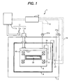
- Fig. 1 is a diagrammatic, partly cross sectional view of a superconducting magnet apparatus according to the first embodiment of the present invention.
- Fig. 2 is a perspective view of a magnetic resonance imaging apparatus to which the present invention is applied.
- Fig. 3 is a block diagram of an NMR apparatus, which employs a superconducting magnet apparatus according to the present invention.
- Figs. 4, 5 and 6 are diagrammatic cross sectional view showing different methods of dispositions of heaters of superconducting magnet apparatuses according to the second embodiment of the present invention.
- the superconducting magnet apparatus 1 shown in Fig. 1 comprises a cryostat, which comprises a coil container 5 for accommodating superconducting coils 3, a vacuum chamber 7 for accommodating the coil container 5, a thermal shield plate or case 9, which surrounds the coil container 5 and disposed in the vacuum chamber 7, etc.
- the superconducting magnet apparatus 1 is provided with a refrigerator 11 for cooling the liquefied cooling medium 10 such as liquid helium in the coil container 5 and the thermal shield plate 9, a control device 13 for controlling etc.
- the coil container 5, which stores the cooling medium 10, is made of a container being able to be hermetic.
- the coil container 5 is provided with a filling port for filling the cooling medium, a discharging conduit for discharging gaseous helium in the coil container 5, and a conduit for detecting a pressure in the coil container 5.
- Fig.1 the discharging conduit 15 for discharging gaseous helium in the coil container 5 is shown.
- the discharging conduit 15 is communicated with the coil container at its one end and is located outside of the vacuum chamber 7 at the other end.
- the other end of the conduit located outside of the vacuum chamber is open to the atmosphere or is normally closed but is opened in accordance with the pressure in the coil container 5.
- the conduit such as the conduit 15, which is arranged outside of the vacuum chamber 7 from the coil container 5, is so disposed as to zigzag in the vacuum chamber 7 so as to thermally insulate the conduit.
- the curved portion of the discharging conduit 15 is provided with a heater 17 to heat the curved portion.
- the heater 17 is electrically connected to the controller 13 by means of a wiring 19.
- the portion of the discharging conduit 15 outside of the vacuum chamber 7 and portion connected to the coil container have a first pressure detecting means 21a and second pressure detecting means 21b, respectively.
- the first and second pressure detecting means 21a, 21b are electrically connected to the controller 13 by means of wiring 19. Since the second pressure detecting means 21b disposed at the position where the conduit is connected to the coil container 5 detects the pressure, which is the same as that in the coil container, the pressure detecting means 21b cab be disposed in the coil container to detect the pressure in the coil container.
- the vacuum chamber 7 is composed of a hermetic vessel.
- the space inside of the vacuum chamber 7 and outside of the coil container 5 is the interior of the vacuum chamber 7 can be vacuum by means of a vacuum pump (not shown), which is installed when needed. After the space is made vacuum, the vacuum is kept to form vacuum layer.
- the thermal shield plate or case 9 shields radiant heat to thermally isolate the coil container 5, whereby the coil container 5 is disposed in the vacuum space in the vacuum chamber 7.
- the refrigerator 11 comprises a cooling head 11a, which is so disposed as to penetrate the vacuum chamber 7 until it arrives at the coil container 5 from the outside of the vacuum chamber 7, a compressor 11b, which for compressing the cooling medium, a cooling circulating conduit 11c, which for circulating the cooling medium through the cooling head 11a and the compressor 11b, etc.
- the cooling head 11a cools the gaseous phase in the coil container 5 thereby to cool the liquefied cooling medium 10 and cools the thermal shield plate 9.
- the cooling head 11a which is disposed in the vertical direction to cool the gaseous phase in the coil container, can effectively cools the cooling medium 10 in the coil container 5 and increases the efficiency of the refrigerator.
- the controller 13 controls the heater 17 in accordance with a pressure difference between the portion of the conduit outside of the vacuum chamber and the portion connected to the coil container or an absolute pressure. If the discharging conduit 15 is clogged, the pressure in the coil container 5 becomes higher than that where the conduit is not clogged. AS a result, the pressure difference between the discharging conduit 15 outside of the vacuum chamber 7 and the conduit connected to the coil container 5. Accordingly, when the pressure in the discharging conduit 15 detected by the second pressure detecting means 21b is higher than the predetermined value with respect to the pressure in the conduit outside of the coil container detected by the first pressure detecting means 21a, the control section 13 starts to control the heater to heat the curved conduit.
- Fig. 1 is a diagrammatic view for showing a superconducting magnetic apparatus, structures, locations, etc of coil container 5, vacuum chamber 7 and superconductor coil 3 may be changed appropriately.
- MRI as shown in Fig. 2, comprises a superconductor magnet apparatus 1, a bed 25, which is capable of going in and out from the space 23 where magnetic field is formed by the opposing superconductor coils 3 of the superconducting magnet apparatus 1, a computer 27 that is an analysis section of signals from a examinee on the bed 25 and controls the superconducting magnet apparatus 1, bed 25, etc.
- the superconducting magnet apparatus 1 and computer 27 are electrically connected by means of wiring 29.
- the space 23 of the superconducting magnet apparatus shown in Fig. 2 corresponds to the space 23 formed in the center of the coil container 5 shown in Fig. 1. Accordingly, in MRI shown in Fig. 2, the opposing superconducting coils 3 are accommodated in the upper and lower portions of a disc shape, and the space 23 is confined by the outer periphery of the vacuum chamber 7. Though the MRI shown in Fig. 2 is provided with the bed for placing a body for examination, the bed 25 may be substituted by a table, etc for placing subjects to be examined.
- NMR as shown in Fig. 3, comprises a superconducting magnet apparatus 1, a sample tube 29 for accommodating a sample and disposed in space 23 formed by opposing superconducting coils 3 of the superconducting magnet apparatus 1, a probe 31 for detecting magnetic nuclear signals from the sample in the sample tube 29, a spectrometer 33 for analyzing the nuclear magnetic resonance signals detected by the probe 31, a computer 35 for controlling the superconducting magnet apparatus 1, the spectrometer 33, etc.
- the computer 35, the superconducting magnet apparatus 1 and the spectrometer 33, and the spectrometer 33 and the probe 31 are electrically connected by means of wiring 37, respectively.
- the space 23 of the superconducting magnet apparatus 1 of NMR shown in Fig. 3 corresponds to the space 23 in the center of the coil container 5 shown in Fig. 1. Accordingly, in NMR shown in Fig. 3, the superconducting magnet apparatus 1 is shown as the state where the superconducting magnet apparatus shown in Fig. 1 is turned by 90 degrees. That is, the space 23 is formed along the vertical axis of the magnet.
- a refrigerator 11 may not be disposed so as to avoid vibration by the refrigerator 11.
- a discharging conduit 15 may be clogged due to freezing of water or nitrogen in the air entering the conduit 15. If the discharging conduit 15 in the superconducting magnet apparatus 1 is clogged due to freezing, the pressure over the clogged portion of the conduit through the interior of the coil container 5 increases. If the pressure detected by the second pressure detecting means 21b becomes higher than a predetermined value higher than the pressure detected by the first pressure detecting means 21a, the heater 17 is supplied with current to heat the discharging conduit 15, thereby to melt the frozen components and to remove clogging as well. As a result, even if quenching or vacuum breakage takes place, the gaseous cooling medium in the coil container 5 can be released through the conduit 15 thereby to prevent breakage of the coil container.
- the superconducting magnet apparatus prevents the breakage of the coil container 5 due to quenching or vacuum breakage.
- the heater 17 can be installed at a position other than the bent position of the discharging conduit 15 in the vacuum chamber 7. The provision of the heater 17 at the position other than the bent position will be explained in the following.
- the discharging conduit 15 may be provided with a gravitational check valve 39, as shown in Fig. 4.
- the gravitational check valve 39 opens when the pressure in the coil container 5 exceeds a predetermined pressure. When the pressure in the coil container becomes lower than the predetermined pressure, the valve closes by gravity. If the gravitational valve 39 is disposed at the discharging conduit 15, there may be a case where the valve does not open because of freezing. Therefore, the clogging of the discharging conduit 15 due to freezing tends to occur in the case of the gravitational valve.
- the heater 17 is disposed at a position to heat the gravitational valve 39 so that the clogging of the discharging conduit 15 extending from the coil container 5 to the outside of the vacuum chamber 7 is surely prevented and that the breakage of the coil container is surely prevented.
- the position where the freezing takes place may be different in accordance with the freezing point of the freezable components contained in the gas entering the discharging conduit disposed outside of the vacuum chamber 7. Accordingly, if the freezing takes place at a position outside of the thermal shield plate or case 9, the heater 17 is disposed at the discharging conduit 15 outside of the thermal shield 9, as shown in Fig. 5.
- the heater 17 is disposed at the discharging conduit 15 inside of the thermal shield 9.
- Whether the heater 17 is disposed inside of the thermal shield 9 or outside of the thermal shield 9 is applied to case where the heater 17 is disposed at the position where the discharging conduit 15 is bent.
- Fig. 1 shows that the heater 17 is disposed at the bent position of the discharging conduit 15 outside of the thermal shield 9, the heater 17 may be disposed at a bent position of the discharging conduit 15 inside of the thermal shield 9, depending on the freezing point of the components in the gas.
- the superconducting magnet apparatus 1 of this embodiment is provided with a first pressure detecting means 21a for detecting a pressure of the discharging conduit at a position located outside of the vacuum chamber 7 and a second pressure detecting means 21b for detecting a pressure of the discharging conduit 15 at a position inside of the vacuum chamber 7.
- the control section 13 supplies current to the heater 17 when the pressure detected by the first pressure detecting means 21a exceeds the predetermined pressure so that the control section judges the clogging of the discharging conduit 15 and eliminates the clogging by heating the conduit with the heater.
- the superconducting magnet apparatus may not be provided with a control section, which compares the pressures detected by the first and second pressure detecting means 21a, 21b and automatically supply current to the heater. In this case, an operator can compare the detected pressures to find clogging of the conduit and judge whether the current is supplied to the heater or not. It is possible to cause the heater 17 work if the magnetic apparatus has no pressure detecting means and the conduit is in a condition that the clogging of the conduit 15 may take place.
- the heater 17 is disposed at only one position for the purpose of explaining the position of the heater.
- the heater 17 may be disposed at positions where clogging due to freezing may take place. By providing a plurality of heaters 17, the clogging of the conduit 15 can surely be prevented.
- the control section stops cooling of the cooling medium in the coil container with the refrigerator 11 when the pressure in the coil container detected by the second pressure detecting means 21b exceeds the predetermined pressure. Further, the control section supplies current to the heater to heat the conduit when the pressure in the coil container exceeds the predetermined pressure.
- the control section 13 of the superconducting magnet apparatus 1 starts to heat the conduit 15 connected to the coil container 5 with the heater 17 when the pressure in the coil container or the pressure in the conduit in the coil container exceeds the predetermined pressure.
- cooling of the cooling medium in the coil container is stopped when the pressure in the coil container exceeds the predetermined pressure.
- gas containing freezable components such as water, nitrogen, etc
- the heater 17 may be disposed at any positions in accordance with kinds of freezable components or the structure of the superconducting magnet apparatus.
- the pressure in the coil container 5 exceeds the predetermined pressure, cooling of the cooling medium with the refrigerator is stopped. Accordingly, it is possible to prevent negative pressure in the coil container and to prevent clogging due to freezing in the conduit such as the discharging conduit 15. Thus, even if the remaining liquid cooling medium is vaporized by quench or vacuum breakage after the cooling medium in the coil container is removed. Since the conduit is not clogged, vaporized cooling medium is discharged from the coil container. That is, it is possible to prevent destruction of the coil container 5 due to quench or vacuum breakage caused by clogging of the conduit.
- the heater 17 when the pressure in the coil container 5 exceeds the predetermined pressure, the heater 17 is supplied with current to heat the conduit 15. Therefore, even if freezable components such as water or nitrogen enter the conduit 15, the freezing in the conduit 15 is prevented.
- the heater 17 for heating the conduit or the first pressure detecting means 21a may be omitted. It is possible to employ both of the above mentioned control method and the previously mentioned control method.
- the heater 17 may be disposed to a position not located at the bent position of the discharging conduit 15. However, the heater 17 electrically connected to a power source (not shown) by means of wiring 19 should be disposed as close to the conduit 15 as possible.
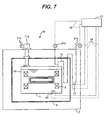
- Fig. 7 shows a diagrammatic cross sectional view of the superconducting magnet apparatus according to the present invention.
- the same reference numerals as those in the previous embodiments indicate the same components; thus explanation will be omitted to avoid redundancy. Only different point and features from the previous embodiments are described in the following.
- a purge heater is connected to the control section for forming a heating section with the heater so that the cooling medium in the coil container is heated with the purge heater when the pressure in the coil container becomes lower than a predetermined pressure.
- the superconducting magnet apparatus 41 in this embodiment has, as shown in Fig. 7, a control section 13 to which a heater 17 and a purge heater 43, disposed in the cooling medium in the coil container, for heating the cooling medium are electrically connected.
- the control section 13 supplies current to the purge heater 43 to heat the liquid cooling medium when the pressure, detected by the second pressure detecting means 21b, in the coil container 5 becomes lower than the predetermined pressure.
- the predetermined pressure at which the control section starts to supply current to the purge heater 43 is set to a pressure higher than the atmospheric pressure.
- the pressure of the coil container can be kept positive pressure since the cooling medium is heated by the purge heater 43 to be vaporized when the pressure in the coil container becomes lower than the predetermined pressure.
- Fig. 8 is a diagrammatic cross sectional view of the superconducting magnetic apparatus of the present invention. Descriptions of the same elements as those in the previous embodiments are omitted to avoid redundancy, but only different points are explained.
- a burst portion is disposed whereby gaseous cooling medium is discharged through the burst portion when the pressure in the conduit exceeds a predetermined pressure. That is, the superconducting magnet apparatus 45, as shown in Fig. 8, is provided with a burst portion 47 at a space position where the discharging conduit 15 is located at a position surrounded by the thermal shield 9 in the vacuum chamber 7.
- the burst portion 47 is so designed as to break its wall when the pressure in the discharging conduit exceeds the predetermined pressure so that the conduit communicates the vacuum chamber.
- the burst portion may be made of a bellows of which wall thickness is thinner than that of other portion. A pressure at which the burst portion is broken should be lower than the pressure to which the coil container 5 withstands.
- the vacuum chamber 7 may be provided with a pressure releasing mechanism such as a safety valve for releasing the pressure in the vacuum chamber when the pressure exceeds the predetermined pressure. As far as the pressure mechanism is disposed, the pressure in the vacuum chamber would not exceed the withstanding pressure of the vacuum chamber and the vacuum chamber would not be broken, even if the cooling medium flows into the vacuum chamber from the broken burst portion 47.
- a pressure releasing mechanism such as a safety valve for releasing the pressure in the vacuum chamber when the pressure exceeds the predetermined pressure.
- the burst portion 47 is disposed to the discharging conduit 15 within the space confined by the thermal shield 9 in the vacuum chamber 7.
- the burst portion since the position where the clogging of the conduit may change according to freezing points of the components in the gas, the burst portion may be disposed to the conduit located in the space between the wall of the vacuum chamber and the thermal shield 9. Further, the above-mentioned burst portions may be employed in one apparatus so that the breakage of the coil container due to quenching or vacuum breakage caused by clogging of the conduit is more surely prevented.
- this embodiment shows a structure that employs only the burst portion 47 disposed to the conduit 15 within the vacuum chamber 7, the burst portion 47 may be combined with the heaters or a purge heater shown in the previous embodiments. Further, a mechanism for stopping cooling the cooling medium with the refrigerator may be combined with the above elements.
- the refrigerator 11 is employed; the refrigerator may be omitted, however.
- the refrigerator is not limited to the vertical type as shown in figures, but a inclined type or horizontal type refrigerator may be employed.
- the present invention can be applied to not only superconducting magnet apparatuses for MRI or NMR, but to various applications of the superconducting magnet apparatuses for other apparatuses.
Landscapes
- Engineering & Computer Science (AREA)
- Power Engineering (AREA)
- Chemical & Material Sciences (AREA)
- Combustion & Propulsion (AREA)
- Physics & Mathematics (AREA)
- Mechanical Engineering (AREA)
- Thermal Sciences (AREA)
- General Engineering & Computer Science (AREA)
- Containers, Films, And Cooling For Superconductive Devices (AREA)
- Magnetic Resonance Imaging Apparatus (AREA)
Abstract
Description
Patent document No. 1: Japanese patent laid-open 05-55032 (
Patent document No. 1: Japanese patent laid-open 09-64425 (Pages 6 - 8, Fig. 1)
Claims (15)
- A superconducting magnet apparatus comprising a coil container for accommodating one or more superconducting coils and liquefied cooling medium for cooling the coils down to the critical temperature or lower of a superconductor constituting the coils, a vacuum chamber for accommodating the coil container and for vacuum insulation of the coil container from the atmosphere, and a conduit communicating the coil container at one end thereof and extending to the outside of the vacuum chamber at the other end, wherein at least one heating device for heating the conduit is disposed at one or more positions of the conduit located within the vacuum chamber.
- The superconducting magnet apparatus according to claim 1, wherein the conduit is arranged zigzag in the vacuum chamber, and wherein the heating device is disposed at a bent position of the conduit.
- The superconducting apparatus according to claim 1, wherein the conduit has a neck portion where an inner diameter is smaller than the other portion, the heating device being disposed to the neck portion.
- The superconducting apparatus according to claim 1, wherein the conduit is a discharging conduit for discharging gaseous cooling medium in the coil container, and wherein the apparatus is provided with a valve that opens when a pressure in the coil container exceeds a predetermined pressure, the heating device being at a position to heat the valve.
- The superconducting apparatus according to claim 1, wherein the apparatus has a thermal shield plate surrounding the coil container in the vacuum chamber, the heating device being disposed to the conduit at a position between the thermal shield plate and the coil container.
- The superconducting apparatus according to claim 1, wherein the apparatus has a thermal shield plate surrounding the coil container, the heating device being disposed to the conduit at a position between the thermal shield plate and the vacuum chamber.
- The superconducting apparatus according to claim 1, wherein the apparatus is provided with a first pressure detecting means for detecting a pressure in the conduit positioned in the vacuum chamber or in the coil container and a second pressure detecting means for detecting a pressure in the conduit positioned outside of the vacuum chamber.
- The superconducting apparatus according to claim 1, wherein the apparatus is provided with a control section for effecting heating with the heating device when the detected pressure by the second pressure detecting means is higher than a detected pressure by the first pressure detecting means by a predetermined value.
- The superconducting apparatus according to claim 1, which further comprises a pressure detecting means for detecting a pressure in the conduit in the vacuum chamber or a pressure in the coil container, a refrigerator for cooling the cooling medium in the coil container, and a control section for controlling the refrigerator, wherein the control section stops cooling of the cooling medium in the coil container by the refrigerator when the detected pressure by the pressure detecting means is higher than a detected pressure.
- The superconducting magnet apparatus according to claim 1, further comprising a pressure detecting means for detecting a pressure in the conduit in the vacuum container or a pressure in the coil container, a refrigerator for cooling the cooling medium in the coil container, and a control section for controlling the refrigerator,
wherein the control section stops cooling of the cooling medium by the refrigerator when the detected pressure by the pressure detecting means is higher than a predetermined pressure, and causes the heating device start to heat. - The superconducting magnet apparatus according to claim 1, which further comprises a control section for controlling the refrigerator, wherein the control section effects the heating device to work when the detected pressure in the conduit in the vacuum chamber or the detected pressure in the coil container becomes lower than a predetermined value.
- The superconducting magnet apparatus according to claim 1, further comprising a heating device for heating the cooling medium, a pressure detecting means for detecting a pressure in the conduit in the vacuum chamber or a pressure in the coil container, and a control section for controlling the heating device, wherein the control section causes the heating device work when the detected pressure in the conduit in the vacuum chamber or the detected pressure in the coil container becomes lower than a predetermined value.
- The superconducting magnet apparatus according to claim 1, which comprises at least one burst portion for letting gaseous cooling medium flow out therefrom, the burst portion being disposed to the conduit within the vacuum container and being so designed as to be broken when the pressure in the conduit becomes higher than a predetermined value.
- A nuclear magnetic resonance imaging apparatus comprising the superconducting magnetic apparatus according to claim 1, an analysis section for analyzing nuclear magnetic resonance signals from the examinee in a space formed between the superconducting coils, and an imaging section for imaging the signals.
- A nuclear magnetic resonance apparatus comprising
the superconducting magnetic apparatus according to claim 1, a probe for detecting nuclear magnetic resonance signals from a sample tube placed in a space formed between the superconducting coils for accommodating a sample therein, and an analysis section for analyzing nuclear magnetic resonance signals from the sample.
Applications Claiming Priority (2)
| Application Number | Priority Date | Filing Date | Title |
|---|---|---|---|
| JP2004121511A JP2005310811A (en) | 2004-04-16 | 2004-04-16 | Superconducting magnet device |
| JP2004121511 | 2004-04-16 |
Publications (2)
| Publication Number | Publication Date |
|---|---|
| EP1587114A2 true EP1587114A2 (en) | 2005-10-19 |
| EP1587114A3 EP1587114A3 (en) | 2008-02-27 |
Family
ID=34940841
Family Applications (1)
| Application Number | Title | Priority Date | Filing Date |
|---|---|---|---|
| EP05252349A Withdrawn EP1587114A3 (en) | 2004-04-16 | 2005-04-15 | Superconducting magnet apparatus |
Country Status (3)
| Country | Link |
|---|---|
| EP (1) | EP1587114A3 (en) |
| JP (1) | JP2005310811A (en) |
| CN (1) | CN1684207A (en) |
Cited By (5)
| Publication number | Priority date | Publication date | Assignee | Title |
|---|---|---|---|---|
| DE102005058647B3 (en) * | 2005-12-08 | 2007-08-09 | Siemens Ag | Quenching device for triggering a quench during raised water level has a cryogenic magnet and a magnetic resonance tomography device |
| CN101923148A (en) * | 2010-05-21 | 2010-12-22 | 南京丰盛超导技术有限公司 | Compact cold-junction container for superconductive magnet |
| US9958519B2 (en) | 2011-12-22 | 2018-05-01 | General Electric Company | Thermosiphon cooling for a magnet imaging system |
| US10490329B2 (en) | 2015-04-10 | 2019-11-26 | Mitsubishi Electric Corporation | Superconducting magnet |
| WO2025093421A1 (en) * | 2023-10-31 | 2025-05-08 | Bruker Switzerland Ag | Device for regulating the pressure in a helium tank of an nmr magnet, comprising two pressure sensors |
Families Citing this family (16)
| Publication number | Priority date | Publication date | Assignee | Title |
|---|---|---|---|---|
| JP4814630B2 (en) * | 2005-12-21 | 2011-11-16 | 三菱電機株式会社 | Superconducting magnet system |
| JP4796995B2 (en) * | 2007-06-11 | 2011-10-19 | 株式会社日立製作所 | Superconducting magnet device, magnetic resonance imaging device using the same, and nuclear magnetic resonance device |
| JP2009082308A (en) * | 2007-09-28 | 2009-04-23 | Ge Medical Systems Global Technology Co Llc | Magnetic resonance imaging apparatus |
| JP5322489B2 (en) * | 2008-04-29 | 2013-10-23 | 三菱電機株式会社 | Superconducting magnet |
| GB2460022B (en) * | 2008-05-12 | 2010-04-07 | Siemens Magnet Technology Ltd | Passive overpressure and underpressure protection for a cryogen vessel |
| CN101884532B (en) * | 2009-05-15 | 2011-09-21 | 美时医疗技术(上海)有限公司 | Superconductive magnetic resonance imager as well as manufacturing method and application |
| JP2010283186A (en) * | 2009-06-05 | 2010-12-16 | Hitachi Ltd | Refrigerator cooled superconducting magnet |
| US8729894B2 (en) * | 2010-07-30 | 2014-05-20 | General Electric Company | System and method for operating a magnetic resonance imaging system during ramping |
| CN103377788A (en) * | 2012-04-27 | 2013-10-30 | 中国科学院高能物理研究所 | Superconducting magnet system |
| US20160291104A1 (en) * | 2013-11-29 | 2016-10-06 | Hitachi, Ltd. | Magnetic resonance imaging apparatus |
| CN104865982B (en) * | 2014-02-26 | 2018-04-24 | 西门子(深圳)磁共振有限公司 | A kind of magnetic resonance imaging system and its pressure control device |
| CN104052040B (en) * | 2014-06-24 | 2017-05-31 | 广东电网公司电网规划研究中心 | A kind of saturable core type superconductive current limiter of utilization nitrogen reinforced insulation performance |
| DE102016211801B4 (en) * | 2016-06-30 | 2022-07-14 | Festo Se & Co. Kg | System with cryostat arrangement |
| CN108630376A (en) * | 2018-03-29 | 2018-10-09 | 杭州汉胜科磁体设备有限公司 | Superconducting magnet two level cooling device and two level cooling means |
| CN109872857B (en) * | 2019-02-14 | 2021-07-27 | 中国电力科学研究院有限公司 | Low temperature back field magnet and high temperature superconducting unit AC loss measurement device |
| CN114520086B (en) * | 2020-11-18 | 2024-12-20 | 松山湖材料实验室 | Low temperature cooling device, cooling system and operation method of dry superconducting magnet |
Family Cites Families (3)
| Publication number | Priority date | Publication date | Assignee | Title |
|---|---|---|---|---|
| JPS5628364A (en) * | 1979-08-09 | 1981-03-19 | Mitsubishi Electric Corp | Emergency gas discharging device |
| JP3045638B2 (en) * | 1994-07-04 | 2000-05-29 | 株式会社日立製作所 | Superconducting device and operating method thereof |
| GB2421299B (en) * | 2004-12-16 | 2010-09-29 | Gen Electric | System and method for melting ice in an exhaust tube of a container holding helium |
-
2004
- 2004-04-16 JP JP2004121511A patent/JP2005310811A/en active Pending
-
2005
- 2005-04-11 CN CN 200510064507 patent/CN1684207A/en active Pending
- 2005-04-15 EP EP05252349A patent/EP1587114A3/en not_active Withdrawn
Cited By (5)
| Publication number | Priority date | Publication date | Assignee | Title |
|---|---|---|---|---|
| DE102005058647B3 (en) * | 2005-12-08 | 2007-08-09 | Siemens Ag | Quenching device for triggering a quench during raised water level has a cryogenic magnet and a magnetic resonance tomography device |
| CN101923148A (en) * | 2010-05-21 | 2010-12-22 | 南京丰盛超导技术有限公司 | Compact cold-junction container for superconductive magnet |
| US9958519B2 (en) | 2011-12-22 | 2018-05-01 | General Electric Company | Thermosiphon cooling for a magnet imaging system |
| US10490329B2 (en) | 2015-04-10 | 2019-11-26 | Mitsubishi Electric Corporation | Superconducting magnet |
| WO2025093421A1 (en) * | 2023-10-31 | 2025-05-08 | Bruker Switzerland Ag | Device for regulating the pressure in a helium tank of an nmr magnet, comprising two pressure sensors |
Also Published As
| Publication number | Publication date |
|---|---|
| EP1587114A3 (en) | 2008-02-27 |
| JP2005310811A (en) | 2005-11-04 |
| CN1684207A (en) | 2005-10-19 |
Similar Documents
| Publication | Publication Date | Title |
|---|---|---|
| EP1587114A2 (en) | Superconducting magnet apparatus | |
| JP4854396B2 (en) | Cryostat structure with low-temperature refrigerator | |
| US7310954B2 (en) | Cryogenic system | |
| US20060021355A1 (en) | Cryostat configuration | |
| US7982566B2 (en) | Cryostat having a magnet coil system, which comprises an LTS section and an HTS section, which is arranged in the vacuum part | |
| US4655045A (en) | Cryogenic vessel for a superconducting apparatus | |
| GB2492645A (en) | Hermetically sealed cryocooler sleeve to avoid loss of cryogen during superconducting magnet quench | |
| CN101994903B (en) | Superconducting magnet cryogen quench path outlet assembly or method | |
| US20110120147A1 (en) | Pressurized Superfluid Helium Cryostat | |
| EP0937953A1 (en) | Refrigerator | |
| EP3655978B1 (en) | Superconducting magnet with cold head thermal path cooled by heat exchanger | |
| US9014770B2 (en) | Magnetic field generation device with alternative quench device | |
| CN100490740C (en) | Magnetic resonance imaging device and maintenance method therefor | |
| JP2001027464A (en) | Superconducting electromagnet device | |
| US11953570B2 (en) | NMR measuring assembly with cold bore of the cryostat | |
| JP4790421B2 (en) | Cryostat structure with quench seal | |
| JP4814630B2 (en) | Superconducting magnet system | |
| US10481222B2 (en) | Fluid path insert for a cryogenic cooling system | |
| JP4796995B2 (en) | Superconducting magnet device, magnetic resonance imaging device using the same, and nuclear magnetic resonance device | |
| CN114270118B (en) | Cryogenic cooling system with vent | |
| JP2006165009A (en) | Superconducting magnet device, and NMR analyzer, MRI device or ICR mass spectrometer using this superconducting magnet device | |
| WO2018172200A1 (en) | Thermal bus heat exchanger for superconducting magnet | |
| JP2007005552A (en) | Cryostat for superconducting magnet | |
| JP2009146934A (en) | Cryostat for superconducting electromagnet | |
| JPH08125241A (en) | Cryostat |
Legal Events
| Date | Code | Title | Description |
|---|---|---|---|
| PUAI | Public reference made under article 153(3) epc to a published international application that has entered the european phase |
Free format text: ORIGINAL CODE: 0009012 |
|
| 17P | Request for examination filed |
Effective date: 20050504 |
|
| AK | Designated contracting states |
Kind code of ref document: A2 Designated state(s): AT BE BG CH CY CZ DE DK EE ES FI FR GB GR HU IE IS IT LI LT LU MC NL PL PT RO SE SI SK TR |
|
| AX | Request for extension of the european patent |
Extension state: AL BA HR LV MK YU |
|
| PUAL | Search report despatched |
Free format text: ORIGINAL CODE: 0009013 |
|
| AK | Designated contracting states |
Kind code of ref document: A3 Designated state(s): AT BE BG CH CY CZ DE DK EE ES FI FR GB GR HU IE IS IT LI LT LU MC NL PL PT RO SE SI SK TR |
|
| AX | Request for extension of the european patent |
Extension state: AL BA HR LV MK YU |
|
| RIC1 | Information provided on ipc code assigned before grant |
Ipc: H01F 6/04 20060101ALN20080118BHEP Ipc: F25D 21/08 20060101ALI20080118BHEP Ipc: H01F 6/02 20060101ALI20080118BHEP Ipc: H01F 6/00 20060101AFI20050610BHEP |
|
| AKX | Designation fees paid |
Designated state(s): DE FR GB IT |
|
| STAA | Information on the status of an ep patent application or granted ep patent |
Free format text: STATUS: THE APPLICATION IS DEEMED TO BE WITHDRAWN |
|
| 18D | Application deemed to be withdrawn |
Effective date: 20080828 |