EP1587099A2 - Reduced recovery time for perpendicular recording systems - Google Patents
Reduced recovery time for perpendicular recording systems Download PDFInfo
- Publication number
- EP1587099A2 EP1587099A2 EP05252398A EP05252398A EP1587099A2 EP 1587099 A2 EP1587099 A2 EP 1587099A2 EP 05252398 A EP05252398 A EP 05252398A EP 05252398 A EP05252398 A EP 05252398A EP 1587099 A2 EP1587099 A2 EP 1587099A2
- Authority
- EP
- European Patent Office
- Prior art keywords
- read
- low frequency
- frequency corner
- corner
- transition
- Prior art date
- Legal status (The legal status is an assumption and is not a legal conclusion. Google has not performed a legal analysis and makes no representation as to the accuracy of the status listed.)
- Withdrawn
Links
Images


Classifications
-
- G—PHYSICS
- G11—INFORMATION STORAGE
- G11B—INFORMATION STORAGE BASED ON RELATIVE MOVEMENT BETWEEN RECORD CARRIER AND TRANSDUCER
- G11B20/00—Signal processing not specific to the method of recording or reproducing; Circuits therefor
- G11B20/10—Digital recording or reproducing
- G11B20/10009—Improvement or modification of read or write signals
- G11B20/10046—Improvement or modification of read or write signals filtering or equalising, e.g. setting the tap weights of an FIR filter
- G11B20/10203—Improvement or modification of read or write signals filtering or equalising, e.g. setting the tap weights of an FIR filter baseline correction
-
- G—PHYSICS
- G04—HOROLOGY
- G04B—MECHANICALLY-DRIVEN CLOCKS OR WATCHES; MECHANICAL PARTS OF CLOCKS OR WATCHES IN GENERAL; TIME PIECES USING THE POSITION OF THE SUN, MOON OR STARS
- G04B47/00—Time-pieces combined with other articles which do not interfere with the running or the time-keeping of the time-piece
-
- G—PHYSICS
- G04—HOROLOGY
- G04B—MECHANICALLY-DRIVEN CLOCKS OR WATCHES; MECHANICAL PARTS OF CLOCKS OR WATCHES IN GENERAL; TIME PIECES USING THE POSITION OF THE SUN, MOON OR STARS
- G04B37/00—Cases
- G04B37/0008—Cases for pocket watches and wrist watches
-
- G—PHYSICS
- G04—HOROLOGY
- G04B—MECHANICALLY-DRIVEN CLOCKS OR WATCHES; MECHANICAL PARTS OF CLOCKS OR WATCHES IN GENERAL; TIME PIECES USING THE POSITION OF THE SUN, MOON OR STARS
- G04B37/00—Cases
- G04B37/12—Cases for special purposes, e.g. watch combined with ring, watch combined with button
- G04B37/125—Cases for special purposes, e.g. watch combined with ring, watch combined with button allowing note taking
-
- G—PHYSICS
- G11—INFORMATION STORAGE
- G11B—INFORMATION STORAGE BASED ON RELATIVE MOVEMENT BETWEEN RECORD CARRIER AND TRANSDUCER
- G11B20/00—Signal processing not specific to the method of recording or reproducing; Circuits therefor
- G11B20/10—Digital recording or reproducing
- G11B20/10009—Improvement or modification of read or write signals
-
- G—PHYSICS
- G11—INFORMATION STORAGE
- G11B—INFORMATION STORAGE BASED ON RELATIVE MOVEMENT BETWEEN RECORD CARRIER AND TRANSDUCER
- G11B20/00—Signal processing not specific to the method of recording or reproducing; Circuits therefor
- G11B20/10—Digital recording or reproducing
- G11B20/14—Digital recording or reproducing using self-clocking codes
- G11B20/1403—Digital recording or reproducing using self-clocking codes characterised by the use of two levels
-
- G—PHYSICS
- G11—INFORMATION STORAGE
- G11B—INFORMATION STORAGE BASED ON RELATIVE MOVEMENT BETWEEN RECORD CARRIER AND TRANSDUCER
- G11B5/00—Recording by magnetisation or demagnetisation of a record carrier; Reproducing by magnetic means; Record carriers therefor
- G11B5/02—Recording, reproducing, or erasing methods; Read, write or erase circuits therefor
- G11B5/09—Digital recording
-
- G—PHYSICS
- G11—INFORMATION STORAGE
- G11B—INFORMATION STORAGE BASED ON RELATIVE MOVEMENT BETWEEN RECORD CARRIER AND TRANSDUCER
- G11B5/00—Recording by magnetisation or demagnetisation of a record carrier; Reproducing by magnetic means; Record carriers therefor
- G11B5/127—Structure or manufacture of heads, e.g. inductive
- G11B5/1278—Structure or manufacture of heads, e.g. inductive specially adapted for magnetisations perpendicular to the surface of the record carrier
-
- H—ELECTRICITY
- H04—ELECTRIC COMMUNICATION TECHNIQUE
- H04H—BROADCAST COMMUNICATION
- H04H40/00—Arrangements specially adapted for receiving broadcast information
-
- G—PHYSICS
- G11—INFORMATION STORAGE
- G11B—INFORMATION STORAGE BASED ON RELATIVE MOVEMENT BETWEEN RECORD CARRIER AND TRANSDUCER
- G11B5/00—Recording by magnetisation or demagnetisation of a record carrier; Reproducing by magnetic means; Record carriers therefor
- G11B2005/0002—Special dispositions or recording techniques
- G11B2005/0005—Arrangements, methods or circuits
- G11B2005/001—Controlling recording characteristics of record carriers or transducing characteristics of transducers by means not being part of their structure
-
- G—PHYSICS
- G11—INFORMATION STORAGE
- G11B—INFORMATION STORAGE BASED ON RELATIVE MOVEMENT BETWEEN RECORD CARRIER AND TRANSDUCER
- G11B5/00—Recording by magnetisation or demagnetisation of a record carrier; Reproducing by magnetic means; Record carriers therefor
- G11B5/012—Recording on, or reproducing or erasing from, magnetic disks
-
- H—ELECTRICITY
- H04—ELECTRIC COMMUNICATION TECHNIQUE
- H04H—BROADCAST COMMUNICATION
- H04H2201/00—Aspects of broadcast communication
- H04H2201/10—Aspects of broadcast communication characterised by the type of broadcast system
- H04H2201/11—Aspects of broadcast communication characterised by the type of broadcast system digital multimedia broadcasting [DMB]
Definitions
- the present invention relates to a system and method for reducing the recovery time required following transitions between write and read modes in a perpendicular recording disk drive system.
- a hard disk drive (HDD) preamplifier has two primary modes, read mode and write mode.
- a critical and challenging specification for an HDD preamplifier is the time required to switch from the write mode to the read mode and to recover the reader output baseline.
- This write-to-read time is affected by transient signals injected into the preamplifier that come both internal and external sources.
- the effect of transient signals on the write-to-read time is greatest in perpendicular recording systems.
- Perpendicular recording systems require the ability to pass very low frequency data, which requires a reduction the preamp lifier's low frequency corner from conventional longitudinal system requirements. A reduction in low frequency corner extends the amount of time needed to recover from transients. This increases the sensitivity to transients, which can increase the baseline wander and therefore the write-to-read recovery time. Baseline wander is also undesirable for the read channel data recovery system because it makes it more difficult for the variable gain amplifier (VGA) to track the servo data.
- VGA variable gain amplifier
- the present invention is a method and apparatus for reading user data from a medium having servo data and user data encoded thereon.
- the user data is read with a read/write head that is operable in a write mode and a read mode.
- Servo data is read in a time window following a transition from write mode to read mode, with a frequency passband that has a first low frequency corner.
- User data is read from the medium after expiration of the time window, with a frequency passband that has a second low frequency corner that is lower than the first low frequency corner.
- FIG. 1 is a block diagram of exemplary hard disk drive (HDD) system 10.
- HDD system 10 includes media 12, read/write head(s) 14, preamplifier 16 connected to read/write head(s) 14 by actuator/interconnect 18, read channel 20, motor controller 22, and hard disk controller 24.
- Media 12 stores data in a nonvolatile format, and typically takes the form of a rigid, rotatable magnetic or op tical disk.
- Read/write head(s) 14 are used to recover (read) data from media 12 and to record (write) data to media 12.
- Preamplifier 16 is a circuit that amplifies the very low voltage signals obtained by read/write head(s) 14 in a read operation, and that converts the low voltage inputs from read channel 20 into high current signals for drivingread/writehead(s) 14 during a write operation.
- Read channel 20 detects and decodes signals received from preamplifier 16 obtained in a read operation, and encodes user data for preamplifier 16 that is to be written to media 12.
- Read channel 20 also includes a servo demodulation circuit that is used by motor controller 22 in a closed loop system to maintain read/write head(s) 14 centered over a desired track of media 12.
- Motor controller 22 is used to control actuator/interconnect 18 to position read/write head 14 over the desired track of media 12.
- Hard disk controller 24 controls and coordinates the operations of all of the components of HDD system 10.
- FIG. 2 is a diagram illustrating an exemplary configuration of media 12, showing the division of media 12 into user data sectors 30 and servo data sectors 32.
- Servo data sectors 32 are sometimes referred to in the art as servo wedges.
- the disk drive sy stem utilizes the information stored in servo data sectors 32 to correctly position the read/write heads over a desired track of media 12. Therefore, servo information from servo data sectors 32 must be read before the data stored in user data sectors 30 can be recovered.
- servo data and user data each contain only relatively high frequency content. This fact allows preamplifier 16 (FIG. 1), to filter out low frequency signals with a relatively high low frequency corner(low frequency border of the filter passband), since neither the servo datanor the user data have meaningful low frequency content.
- a relatively high low frequency corner allows preamplifier 16 to recover quickly from a write-to-read transition, as the higher frequency signals involved allow for faster response by the circuit.
- preamplifier 16 For perpendicular recording systems, it is not possible for preamplifier 16 (FIG. 1) to have the same relatively high low frequency corner as was employed in longitudinal recording systems. The reason for this is that user data in a perpendicular recording sy stem includes low frequency content that is important to improve the signal-to-noise ratio of the perpendicular recording system, which in turn improves the capacity of the system. As a result, preamplifier 16 is configured in perpendicular recording systems to pass low frequency content, meaning that the low frequency corner of the passband of preamplifier 16 is relatively low. This results in slower write-to-read recovery than was possible in a longitudinal recording system, as the lower frequency signals involved dictate slower response by the circuit.
- FIG. 3A shows a waveform illustrating exemplary user data signal 40 in a perpendicular recording system
- FIG. 3B shows a waveform illustrating exemplary servo data signal 42 in a perpendicular recording system.
- User data signal 40 includes low frequency content, which is used by the read channel to improve the signal-to-noise ratio of the system.
- Servo data signal 42 is similar to servo data signals employed in longitudinal recording systems, and does not include meaningful low frequency content.
- the present invention is based on the fact that perpendicular recording sy stems do not utilize any low frequency content of the servo data signal, and that at least one servo wedge must be read prior to reading user data.
- the filtering performance of preamplifier 16 (FIG. 1) is controlled to have a relatively high low frequency corner immediately following a write-to-read transition (when servo data is beingread), and to have a reduced low frequency corner after the servo data has been read, so that the low frequency content of the user data can be recovered and used appropriately.
- FIG. 4 is a flow diagram illustrating the performance of the filtering op eration of preamp lifier 16 (FIG. 1) in a perpendicular recording sy stem according to the present invention.
- a write-to-read transition occurs as indicated by box 50, meaning that servo and user data are to be read and the recovered signals are to be filtered by the preamplifier.
- Servo data is read first, as indicated by box 52, with the preamplifier filtering the data with a passband that has a relatively high low frequency corner, similar to the passband that was possible in preamplifier used for longitudinal recording.
- the relatively high low frequency corner of the preamp lifier while servo data is being read is possible because the servo data does not have meaningful low frequency content, as described above with respect to FIG. 3B.
- the time following the write-to-read transition (box 50) is also the critical time for the preamplifier circuitry to recover from the transition, and using this time to read servo data with a relatively high low frequency corner results in fasterrecovery time following the transition than if the sy stem performed a read operation with a lower low frequency corner (such as is required to read user data in a perpendicular recording system).
- Servo data is read (box 52) with the relatively high low frequency corner until a triggering event occurs, as indicated by decision box 54.
- the triggering event signals that the recovery from the write-to-read transition is complete, and/or that the reading of servo data is complete or near complete.
- the triggering event may be implemented in a number of different ways, such as by the expiration of a delay circuit signal or by the transition of a servo read signal from read channel circuitry, for example. Once the triggering even occurs, the preamplifier transitions to a relatively low low frequency corner, as indicated by box 56.
- user data is read with a relatively low low frequency corner as indicated by box 58, which is required in the perpendicular recording system to utilize the low frequency content of the user data signal, as described above with respect to FIG. 3A.
- the transitioning of the low frequency corner from a relatively high frequency to a relatively low frequency can be done without waiting for the occurrence of a triggering event.
- decision box 54 is eliminated.
- the rate of decrease of the low frequency corner is controlled so that, during the time immediately following the write-to-read transition (when servo data is being read), the low frequency corner is high enough to allow quick recovery from transient signals, and during a later time when user data is being read, the low frequency corner is low enough that the system is able to read the low frequency content that is present in the user data.
- This embodiment can be implemented with a relatively simple circuit, triggered only by a write-to-read transition, and may be advantageous in some applications.
- FIG. 5 is a graph illustrating an exemplary relationship between the low frequency corner of preamplifier 16 (FIG. 1) and time in accordance with the principles of the present invention.
- the low frequency corner of the preamp lifier is high during a servo read time following a write-to-read transition (shown as time 0 in FIG. 5), and then is reduced after the transition has occurred so that user data can be read in a manner that utilizes the low frequency content of the user data signal.
- the relatively high low frequency corner shown at time 0 in FIG. 5
- the reduced low frequency corner is about 200 kilo-Hertz (kHz).
- the transition between the higher low frequency corner (for reading servo data) and the lower low frequency corner (for reading user data) can be achieved in a number of different ways, and can be a slow, gradual transition (as shown by graph 59a) or may be one or more abrupt, stepwise transitions (shown by graph 59b).
- Abrupt transitions have the potential to inject disturbances into the signals obtained from the read head, but are quite simple to implement.
- Gradual transitions may have less effect on the read head signals, but usually require more complex circuitry to be employed, which increases the space required by the circuit and the cost of the circuit. Either type of transition may be used in accordance with the present invention.
- FIG. 6A is a diagram illustrating the timing of signals generated to control the reduction of the low frequency corner of the preamplifier passband in one exemplary implementation of the present invention.
- Timing generator 60 receives read/write signal 62, which indicates whether the system is in write mode or read mode. Upon a transition from write mode to read mode, which is indicated by a change in the state of read/write signal 62, timing generator 60 implements a delay routine to trigger a transition in signals IFM_Bias and IFM_Signal.
- IFM_Bias has a state transition a first delay time after the write-to-read transition (indicated by a state transition of read/write signal 60), and IFM_Signal has a state transition a second delay time after the write-to-read transition.
- timinggenerator 60 may be configured to change the states of signals IFM_Bias and IFM_Signal based on receipt of a signal from the channel circuitry that indicates that servo data is no longer being read (and that user data is to be read).
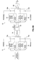
- FIG. 6B is a diagram illustrating exemplary circuitry that is employed to transition the preamplifier from a relatively high low frequency corner immediately after a write-to-read transition occurs to a lower low frequency corner after a delay period following the write-to-read transition.
- Reference signals for biasing the read/write head are provided by MR Bias Reference circuit 70.
- the bias reference signals are connected through filter network 72, which includes normal mode low pass filter 74 and intermediate mode low pass filter 76, to driver circuit 78 which drives read/write head 80.
- Normal mode low pass filter 74 is connected (via switches 79a) when signal IFM_Bias is in a non-active state, and intermediate mode low pass filter 76 is connected (via switches 79b) when signal IFM_Bias is in an active state.
- Read/write head 80 is connected through filter network 82, which includes normal mode high p ass filter 84 and intermediate mode high pass filter 86, to amplifier 88 whose output is the output signal (Vout) of the circuit.
- Normal mode high pass filter 84 is connected (via switches 89a) when signal IFM_Signal is in a non-active state, and intermediate mode high pass filter 86 is connected (via switches 89b) when signal IFM_Signal is in an active state.
- both signal IFM_Bias and IFM_Signal are in an active state, as shown in FIG. 6A.
- the circuit shown in FIG. 6B therefore operates in an intermediate mode (with intermediate mode low pass filter 76 and intermediate mode high pass filter 86 connected).
- Intermediate mode low pass filter 76 passes low frequency signals up to a relatively high frequency, such as signals up to 300 KHz in an exemplary embodiment, to drive read/write head 80.
- Intermediate mode high pass filter passes high frequency signals from read/write head 80 that exceed a relatively high frequency, such as signals exceeding 3 MHz in an exemplary embodiment, for amplification by amplifier 88.
- the response of the biasing portion of the circuit is made faster by the relatively high frequency passband of intermediate mode low pass filter 76, and only relatively high frequency signals obtained by read/write head 80 are passed by intermediate mode high pass filter 86.
- This operation is appropriate for the time following a write-to-read transition, because this is the time when only servo data is read, which has no useful low frequency content, meaningthat no information is lost by passing only high frequency signals obtained from read/write head 80.
- signal IFM_Bias changes to an inactive state (as shown in FIG. 6A).
- signal IFM_Signal also changes to an inactive state (as shown in FIG. 6A).
- normal mode high pass filter 84 which passes high frequency signals above a relatively low threshold frequency, such as 50 KHz in an exemplary embodiment, obtained from read/write head 80.
- a relatively low threshold frequency such as 50 KHz in an exemplary embodiment
- the low frequency signals obtained from read/write head 80 are passed to amplifier 88, which is appropriate for reading user datathat (in a perpendicular recording sy stem) includes useful low frequency content.
- FIGS. 6A and6B is presented as an example of one suitable implementation of the present invention.
- Other implementations are possible, including a configuration in which a gradual reduction of the low frequency corner is commenced immediately when a transition from write mode to read mode occurs.
- the low frequency corner transition is controlled so that, by the time user data is to be read, the low frequency corner is sufficiently low (such as 200 kHz or lower, for example) to allow the low frequency content of the user data to be read and accounted for.
- the present invention provides reduced recovery time following a transition from write mode to read mode in a perpendicular recording system. This improvement is achieved by initially reading servo data following a transition from write mode to read mode with a relatively high low frequency corner, and then reading user data with a relatively low low frequency corner after the occurrence of a triggering event that indicates the closing of the servo data window. As a result, data is read with a high signal to noise ratio, and baseline wander in the read channel is reduced.
Landscapes
- Engineering & Computer Science (AREA)
- Signal Processing (AREA)
- Physics & Mathematics (AREA)
- General Physics & Mathematics (AREA)
- Manufacturing & Machinery (AREA)
- Digital Magnetic Recording (AREA)
- Moving Of The Head To Find And Align With The Track (AREA)
- Signal Processing For Digital Recording And Reproducing (AREA)
Abstract
Description
Claims (20)
- A method of reading userdata with a read/write head that is operable in write mode and read mode from a medium having servo data and user data encoded thereon, the method comprising:reading servo data from the medium in a time window following a transition from write mode to read mode, the reading of servo data being performed with a first frequency passband that has a first low frequency corner; andreading user data from the medium after expiration of the time window, the reading of user data being performed with a second frequency passband that has a second low frequency corner that is lower than the first low frequency corner.
- The method of claim 1, wherein expiration of the time window is signaled by a triggering event.
- The method of claim 2, wherein the triggeringevent is the expiration of a time delay following the transition from write mode to read mode.
- The method of claim 2, wherein the triggering event is a signal from a read channel indicating that user data is to be read.
- The method of claim 2, further comprising:transitioning the first low frequency corner to the second low frequency corner in response to the triggering event in a gradual manner.
- The method of claim 2, further comprising:transitioning the first low frequency corner to the second low frequency corner in response to the triggering event in a stepwise manner.
- The method of claim 1, further comprising:transitioning the first low frequency corner to the second low frequency corner following the transition from write mode to read mode in a gradual manner.
- The method of claim 1, further comprising:transitioning the first low frequency corner to the second low frequency corner following the transition from write mode to read mode in a stepwise manner.
- The method of claim 1, wherein the second low frequency corner is no greater than about 200 kiloHertz.
- A preamplifier circuit for use in a perpendicular recording system that includes a read/write head that is operable in write mode and read mode and a medium that includes servo data and user data encoded thereon, the preamplifier circuit being configured to control operations of the read/write head to:read servo data from the medium in a time window following a transition from write mode to read mode, the reading of servo data being performed with a first frequency passband that has a first low frequency corner; andread user data from the medium after expiration of the time window, the reading of user data being performed with a second frequency passband that has a second low frequency corner that is lower than the first low frequency corner.
- The preamplifier circuit of claim 10, wherein expiration of the time window is signified by a triggering signal.
- The preamplifier circuit of claim 11, wherein the triggering signal is generated a delay time after the transition from write mode to read mode.
- The preamplifier circuit of claim 11, wherein the triggering signal is generated by a read channel coupled to the read/write head.
- The preamplifier circuit of claim 11, including filtering circuitry operable to transition the first low frequency corner to the second low frequency corner in response to the triggering signal in a gradual manner.
- The preamplifier circuit of claim 11, including filtering circuitry operable to transition the first low frequency corner to the second low frequency corner in response to the triggering signal in a stepwise manner.
- The preamplifier circuit of claim 10, including filtering circuitry operable to transition the first low frequency corner to the second low frequency corner in a gradual manner.
- The preamplifier circuit of claim 10, including filtering circuitry operable to transition the first low frequency corner to the second low frequency corner in response to the triggering signal in a stepwise manner.
- The preamplifier circuit of claim 10, wherein the second low frequency corner is no greater than about 200 kiloHertz.
- The preamp lifier circuit of claim 10, realized as an integrated circuit (IC).
- A perpendicular recording system comprising:a read/write head that is operable in write mode and read mode;a medium that includes servo data and user data encoded thereon; anda preamp lifier circuit operatively coupled to the read/write head, ht preamp lifier circuit controlling operations of the read/write head to:read servo data from the medium in a time window following a transition from write mode to read mode, the reading of servo data being performed with a first frequency passband that has a first low frequency corner; andread user data from the medium after expiration of the time window, the reading of user data being performed with a second frequency passband that has a second low frequency corner that is lower than the first low frequency corner.
Applications Claiming Priority (4)
| Application Number | Priority Date | Filing Date | Title |
|---|---|---|---|
| US56270304P | 2004-04-17 | 2004-04-17 | |
| US562703P | 2004-04-17 | ||
| US11/091,352 US7119977B2 (en) | 2004-04-17 | 2005-03-28 | Reduced recovery time for perpendicular recording systems |
| US91352 | 2005-03-28 |
Publications (2)
| Publication Number | Publication Date |
|---|---|
| EP1587099A2 true EP1587099A2 (en) | 2005-10-19 |
| EP1587099A3 EP1587099A3 (en) | 2005-12-28 |
Family
ID=34940881
Family Applications (1)
| Application Number | Title | Priority Date | Filing Date |
|---|---|---|---|
| EP05252398A Withdrawn EP1587099A3 (en) | 2004-04-17 | 2005-04-18 | Reduced recovery time for perpendicular recording systems |
Country Status (4)
| Country | Link |
|---|---|
| US (1) | US7119977B2 (en) |
| EP (1) | EP1587099A3 (en) |
| JP (1) | JP2005310359A (en) |
| KR (1) | KR20060092788A (en) |
Families Citing this family (1)
| Publication number | Priority date | Publication date | Assignee | Title |
|---|---|---|---|---|
| US7440209B1 (en) * | 2005-02-15 | 2008-10-21 | Marvell International Ltd. | Communications channel with programmable coupling |
Family Cites Families (7)
| Publication number | Priority date | Publication date | Assignee | Title |
|---|---|---|---|---|
| US6133784A (en) * | 1997-11-25 | 2000-10-17 | Texas Instruments Incorporated | Fast settling high pass filter with corner frequency adjusting circuit |
| US6252459B1 (en) * | 1999-03-30 | 2001-06-26 | Siemens Microelectronics, Inc. | System and method for a dual bandwidth capacitor multiplying filter |
| US6404578B1 (en) * | 1999-09-28 | 2002-06-11 | Koninklijke Philips Electronics N.V. | Circuit for reduction and optimization of write-to-read settling times in magnetic medium storage devices |
| US6751034B1 (en) | 2000-07-19 | 2004-06-15 | Texas Instruments Incorporated | Preamplifier read recovery parade |
| JP2002100134A (en) * | 2000-09-21 | 2002-04-05 | Toshiba Corp | Perpendicular magnetic recording type magnetic disk drive |
| US6621649B1 (en) | 2000-11-10 | 2003-09-16 | Texas Instruments Incorporated | Write-to-read switching improvement for differential preamplifier circuits in hard disk drive systems |
| US6707624B2 (en) * | 2001-12-07 | 2004-03-16 | Seagate Technology Llc | Method and apparatus for preprocessing low frequencies in perpendicular recording |
-
2005
- 2005-03-28 US US11/091,352 patent/US7119977B2/en not_active Expired - Lifetime
- 2005-04-15 JP JP2005117937A patent/JP2005310359A/en active Pending
- 2005-04-18 EP EP05252398A patent/EP1587099A3/en not_active Withdrawn
- 2005-04-18 KR KR1020050032021A patent/KR20060092788A/en not_active Withdrawn
Also Published As
| Publication number | Publication date |
|---|---|
| KR20060092788A (en) | 2006-08-23 |
| JP2005310359A (en) | 2005-11-04 |
| US7119977B2 (en) | 2006-10-10 |
| EP1587099A3 (en) | 2005-12-28 |
| US20050232018A1 (en) | 2005-10-20 |
Similar Documents
| Publication | Publication Date | Title |
|---|---|---|
| US6735033B1 (en) | Method for recovering from shock events occurring to a disk drive during data write operations to improve data reliability | |
| US5898532A (en) | MR head thermal asperity recovery | |
| JPH0991886A (en) | Data reproduction processing device of disk recording / reproduction device | |
| JPH113504A (en) | Storage device | |
| KR100846002B1 (en) | Write-to-read switching improvement for differential preamplifier circuits in hard disk drive systems | |
| US7821734B2 (en) | Head IC, read circuit and medium storage device | |
| US20030021053A1 (en) | Method and apparatus for optimizing auto gain control of read channel in a disk drive | |
| JP4250589B2 (en) | Head amplifier circuit having remanent demagnetization function of recording head, and magnetic disk apparatus provided with the same | |
| US7119977B2 (en) | Reduced recovery time for perpendicular recording systems | |
| US7203022B2 (en) | Disk device, and positioning control method and signal-processing circuit for head | |
| US7265923B2 (en) | Apparatus and method for controlling inhibition of data writing in disk drive | |
| US7023634B2 (en) | Data channel for processing user data and servo data in a disk drive adopting perpendicular magnetic recording system | |
| US20020089773A1 (en) | Disk drive including preamplifier for perpendicular magnetic recording system | |
| US20050094303A1 (en) | Flying height monitor with servo AGC voltage for write operation in a hard disk drive | |
| US7274523B2 (en) | Read head preamplifier with thermal asperity transient control | |
| US7616394B2 (en) | Storage apparatus, control method and control apparatus | |
| US20040151036A1 (en) | Magnetic head for performing perpendicular magnetic recording in a disk drive | |
| US6072647A (en) | Reproduced signal waveform control device for magnetoresistive head | |
| JP3607672B2 (en) | Magnetic disk apparatus of perpendicular magnetic recording system and recording compensation method applied to the same | |
| Liu et al. | Demonstration and characterization of 14 gb/in/sup 2/recording systems | |
| JP3866487B2 (en) | Disk unit | |
| JP2002251703A (en) | Magnetic recording device | |
| JP2003338146A (en) | Disk device and information recording medium | |
| Cain et al. | Achieving 1 Gbit/in/sup 2/with inductive recording heads | |
| JP2004005839A (en) | Magnetic disk drive |
Legal Events
| Date | Code | Title | Description |
|---|---|---|---|
| PUAI | Public reference made under article 153(3) epc to a published international application that has entered the european phase |
Free format text: ORIGINAL CODE: 0009012 |
|
| AK | Designated contracting states |
Kind code of ref document: A2 Designated state(s): AT BE BG CH CY CZ DE DK EE ES FI FR GB GR HU IE IS IT LI LT LU MC NL PL PT RO SE SI SK TR |
|
| AX | Request for extension of the european patent |
Extension state: AL BA HR LV MK YU |
|
| PUAL | Search report despatched |
Free format text: ORIGINAL CODE: 0009013 |
|
| AK | Designated contracting states |
Kind code of ref document: A3 Designated state(s): AT BE BG CH CY CZ DE DK EE ES FI FR GB GR HU IE IS IT LI LT LU MC NL PL PT RO SE SI SK TR |
|
| AX | Request for extension of the european patent |
Extension state: AL BA HR LV MK YU |
|
| RIC1 | Information provided on ipc code assigned before grant |
Ipc: 7G 11B 5/09 B Ipc: 7G 11B 20/10 A |
|
| AKX | Designation fees paid | ||
| REG | Reference to a national code |
Ref country code: DE Ref legal event code: 8566 |
|
| STAA | Information on the status of an ep patent application or granted ep patent |
Free format text: STATUS: THE APPLICATION IS DEEMED TO BE WITHDRAWN |
|
| 18D | Application deemed to be withdrawn |
Effective date: 20060629 |