EP1587054A2 - Plasma display apparatus and image processing method thereof - Google Patents
Plasma display apparatus and image processing method thereof Download PDFInfo
- Publication number
- EP1587054A2 EP1587054A2 EP05008067A EP05008067A EP1587054A2 EP 1587054 A2 EP1587054 A2 EP 1587054A2 EP 05008067 A EP05008067 A EP 05008067A EP 05008067 A EP05008067 A EP 05008067A EP 1587054 A2 EP1587054 A2 EP 1587054A2
- Authority
- EP
- European Patent Office
- Prior art keywords
- filtering
- value
- video signal
- gray scale
- plasma display
- Prior art date
- Legal status (The legal status is an assumption and is not a legal conclusion. Google has not performed a legal analysis and makes no representation as to the accuracy of the status listed.)
- Withdrawn
Links
- 238000003672 processing method Methods 0.000 title claims abstract description 16
- 238000001914 filtration Methods 0.000 claims abstract description 103
- 238000000034 method Methods 0.000 description 13
- 239000000758 substrate Substances 0.000 description 11
- 238000010586 diagram Methods 0.000 description 10
- 241001270131 Agaricus moelleri Species 0.000 description 7
- 238000009792 diffusion process Methods 0.000 description 7
- 238000013507 mapping Methods 0.000 description 7
- 230000004044 response Effects 0.000 description 6
- 230000004888 barrier function Effects 0.000 description 5
- 230000008859 change Effects 0.000 description 3
- 239000011521 glass Substances 0.000 description 2
- OAICVXFJPJFONN-UHFFFAOYSA-N Phosphorus Chemical compound [P] OAICVXFJPJFONN-UHFFFAOYSA-N 0.000 description 1
- 230000003247 decreasing effect Effects 0.000 description 1
- 230000006866 deterioration Effects 0.000 description 1
- AMGQUBHHOARCQH-UHFFFAOYSA-N indium;oxotin Chemical compound [In].[Sn]=O AMGQUBHHOARCQH-UHFFFAOYSA-N 0.000 description 1
- 229910052751 metal Inorganic materials 0.000 description 1
- 239000002184 metal Substances 0.000 description 1
- 239000000203 mixture Substances 0.000 description 1
- 230000008569 process Effects 0.000 description 1
Images




Classifications
-
- A—HUMAN NECESSITIES
- A44—HABERDASHERY; JEWELLERY
- A44B—BUTTONS, PINS, BUCKLES, SLIDE FASTENERS, OR THE LIKE
- A44B11/00—Buckles; Similar fasteners for interconnecting straps or the like, e.g. for safety belts
- A44B11/005—Buckles combined with other articles, e.g. with receptacles
-
- G—PHYSICS
- G09—EDUCATION; CRYPTOGRAPHY; DISPLAY; ADVERTISING; SEALS
- G09G—ARRANGEMENTS OR CIRCUITS FOR CONTROL OF INDICATING DEVICES USING STATIC MEANS TO PRESENT VARIABLE INFORMATION
- G09G3/00—Control arrangements or circuits, of interest only in connection with visual indicators other than cathode-ray tubes
- G09G3/20—Control arrangements or circuits, of interest only in connection with visual indicators other than cathode-ray tubes for presentation of an assembly of a number of characters, e.g. a page, by composing the assembly by combination of individual elements arranged in a matrix no fixed position being assigned to or needed to be assigned to the individual characters or partial characters
- G09G3/2007—Display of intermediate tones
- G09G3/2018—Display of intermediate tones by time modulation using two or more time intervals
- G09G3/2022—Display of intermediate tones by time modulation using two or more time intervals using sub-frames
-
- G—PHYSICS
- G09—EDUCATION; CRYPTOGRAPHY; DISPLAY; ADVERTISING; SEALS
- G09G—ARRANGEMENTS OR CIRCUITS FOR CONTROL OF INDICATING DEVICES USING STATIC MEANS TO PRESENT VARIABLE INFORMATION
- G09G2320/00—Control of display operating conditions
- G09G2320/02—Improving the quality of display appearance
- G09G2320/0261—Improving the quality of display appearance in the context of movement of objects on the screen or movement of the observer relative to the screen
-
- G—PHYSICS
- G09—EDUCATION; CRYPTOGRAPHY; DISPLAY; ADVERTISING; SEALS
- G09G—ARRANGEMENTS OR CIRCUITS FOR CONTROL OF INDICATING DEVICES USING STATIC MEANS TO PRESENT VARIABLE INFORMATION
- G09G2320/00—Control of display operating conditions
- G09G2320/02—Improving the quality of display appearance
- G09G2320/0266—Reduction of sub-frame artefacts
-
- G—PHYSICS
- G09—EDUCATION; CRYPTOGRAPHY; DISPLAY; ADVERTISING; SEALS
- G09G—ARRANGEMENTS OR CIRCUITS FOR CONTROL OF INDICATING DEVICES USING STATIC MEANS TO PRESENT VARIABLE INFORMATION
- G09G3/00—Control arrangements or circuits, of interest only in connection with visual indicators other than cathode-ray tubes
- G09G3/20—Control arrangements or circuits, of interest only in connection with visual indicators other than cathode-ray tubes for presentation of an assembly of a number of characters, e.g. a page, by composing the assembly by combination of individual elements arranged in a matrix no fixed position being assigned to or needed to be assigned to the individual characters or partial characters
- G09G3/2007—Display of intermediate tones
- G09G3/2044—Display of intermediate tones using dithering
-
- G—PHYSICS
- G09—EDUCATION; CRYPTOGRAPHY; DISPLAY; ADVERTISING; SEALS
- G09G—ARRANGEMENTS OR CIRCUITS FOR CONTROL OF INDICATING DEVICES USING STATIC MEANS TO PRESENT VARIABLE INFORMATION
- G09G3/00—Control arrangements or circuits, of interest only in connection with visual indicators other than cathode-ray tubes
- G09G3/20—Control arrangements or circuits, of interest only in connection with visual indicators other than cathode-ray tubes for presentation of an assembly of a number of characters, e.g. a page, by composing the assembly by combination of individual elements arranged in a matrix no fixed position being assigned to or needed to be assigned to the individual characters or partial characters
- G09G3/2007—Display of intermediate tones
- G09G3/2059—Display of intermediate tones using error diffusion
-
- G—PHYSICS
- G09—EDUCATION; CRYPTOGRAPHY; DISPLAY; ADVERTISING; SEALS
- G09G—ARRANGEMENTS OR CIRCUITS FOR CONTROL OF INDICATING DEVICES USING STATIC MEANS TO PRESENT VARIABLE INFORMATION
- G09G3/00—Control arrangements or circuits, of interest only in connection with visual indicators other than cathode-ray tubes
- G09G3/20—Control arrangements or circuits, of interest only in connection with visual indicators other than cathode-ray tubes for presentation of an assembly of a number of characters, e.g. a page, by composing the assembly by combination of individual elements arranged in a matrix no fixed position being assigned to or needed to be assigned to the individual characters or partial characters
- G09G3/22—Control arrangements or circuits, of interest only in connection with visual indicators other than cathode-ray tubes for presentation of an assembly of a number of characters, e.g. a page, by composing the assembly by combination of individual elements arranged in a matrix no fixed position being assigned to or needed to be assigned to the individual characters or partial characters using controlled light sources
- G09G3/28—Control arrangements or circuits, of interest only in connection with visual indicators other than cathode-ray tubes for presentation of an assembly of a number of characters, e.g. a page, by composing the assembly by combination of individual elements arranged in a matrix no fixed position being assigned to or needed to be assigned to the individual characters or partial characters using controlled light sources using luminous gas-discharge panels, e.g. plasma panels
- G09G3/2803—Display of gradations
Definitions
- the present invention relates to a plasma display apparatus, and more particularly, to a plasma display apparatus and an image processing method thereof for preventing images from blurring when processing the images to improve image quality.
- a plasma display apparatus includes a front substrate, a rear substrate, and barrier ribs formed between the front and rear substrates to construct unit cells. Each cell is charged with a main discharge gas such as Ne, He or a mixture of Ne and He (Ne + He) and an inactive gas including a small quantity of Xe. When discharge occurs according to a high-frequency voltage, the inactive gas generates vacuum ultraviolet rays to make phosphor formed between adjacent barrier ribs emit lights to display images. The plasma display apparatus is thin and light and thus it is being spotlighted as a next generation display device.
- a main discharge gas such as Ne, He or a mixture of Ne and He (Ne + He) and an inactive gas including a small quantity of Xe.
- the inactive gas When discharge occurs according to a high-frequency voltage, the inactive gas generates vacuum ultraviolet rays to make phosphor formed between adjacent barrier ribs emit lights to display images.
- the plasma display apparatus is thin and light and thus it is being spotlighted as a next generation display
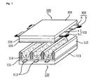
- FIG. 1 illustrates the structure of a conventional plasma display panel.
- the plasma display panel includes a front substrate 100 and a rear substrate 110, which are assembled having a predetermined distance between them.
- the front substrate 100 is constructed such that a plurality of sustain electrode pairs each consisting of a scan electrode 102 and a sustain electrode 103 are arranged on a front glass 101 corresponding to an image display plane.
- the rear substrate 110 is constructed in a manner that a plurality of address electrodes 113 are arranged, intersecting the plurality of sustain electrode pairs, on a rear glass 111.
- the scan electrode 102 and the sustain electrode 103 generate discharge in a discharge cell and sustain lighting of the cell and each of them includes a transparent electrode (a) formed of a transparent ITO (Indium Tin Oxide) and a bus electrode (b) formed of a metal.
- the front substrate 100 is covered with at least one dielectric layer 104 that restrains discharge current of the scan electrode 102 and the sustain electrode 103 and insulates adjacent electrode pairs from each other. MgO is deposited on the dielectric layer 104 to form a protection layer 105 for facilitating a discharge condition.
- the rear substrate 110 includes barrier ribs 112 of a stripe type (or well type) formed thereon in parallel.
- the barrier ribs 112 form a plurality of discharge spaces, that is, discharge cells.
- the plurality of address electrodes 113 which carry out address discharge to generate vacuum ultraviolet rays, are arranged on the rear substrate 110 in parallel with the barrier ribs 112.
- R, G and B phosphors 114 which emit visible rays for displaying images when the address discharge occurs, are coated on the rear substrate 110.
- a dielectric layer 115 for protecting the address electrodes 113 is formed between the address electrodes 113 and the phosphors 114.
- FIG. 2 illustrates a method of displaying images of the conventional plasma display apparatus.
- the plasma display apparatus divides one frame into a plurality of sub-fields having different numbers of times of discharge, and makes the plasma display panel emit light during a sub-field period corresponding to the gray scale of an input video signal, to thereby display an image.
- Each sub-field is divided into a reset period for generating uniform discharge, an address period for selecting a discharge cell, and a sustain period for representing a gray scale in response to the number of times of discharge.
- a frame (16.67ms) corresponding to 1/60 seconds is divided into eight sub-fields.
- Each of the eight sub-fields is divided into a reset period, an address period and a sustain period.
- the plasma display apparatus represents gray scales of an image according to a combination of sub-fields.
- the plasma display apparatus may generate a false contour noise in a moving picture when coarse video signal data is input or a noise is added to a video signal. This false contour noise reduces display quality of the plasma display apparatus.
- a coarse image means a picture having a large luminance difference, displayed for one frame, because of a large gray-level difference between neighboring pixels for one frame.
- Methods for removing the false contour noise of a moving picture include a method of segmenting one sub-field to add one or two sub-fields, a method of re-arranging the sequence of sub-fields, a method of preparing sub-fields having different modes, a method of adding a sub-field and re-arranging the sequence of sub-fields, an error diffusion method and so on.
- a sub-field is added, however, resolution is difficult to increase and the circuit configuration of the plasma display apparatus becomes complicated for lack of sustain period.
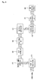
- FIG. 3 is a block diagram of the conventional plasma display apparatus.
- the plasma display apparatus includes a reverse gamma correcting unit 310, a gain controller 320, a half tone unit 330, and a sub-field mapping unit 340.
- the reverse gamma correcting unit 310 reverse-gamma-corrects an input video signal using previously stored gamma data to linearly change a luminance value in response to the gray scale of the video signal.
- the gain controller 320 respectively multiplies the RGB video data signals corrected by the reverse gamma correcting unit 310 by a value adjusted by a user or a set maker to control respective gains of the RGB data signals.
- the user or set maker can set a desired color temperature using the gain controller 320.
- the half tone unit 330 minutely controls gray scales using an error diffusion or dithering method to improve the power of representing gray scales of an image.
- the error diffusion method diffuses an error component of the data from the gain controller. 320 to neighboring cells to minutely control the luminance value. For this, the error diffusion method divides the data from the gain controller 320 into an integer part and a prime part and multiplies the prime part by Floy-Steinberg coefficient to diffuse an error to neighboring cells.
- the sub-field mapping unit 340 divides the data input from the half tone unit 330 into bits, maps the bits to a predetermined sub-field pattern and provides the data to a data aligning unit 350.
- the data aligning unit 350 transforms the data input from the sub-field mapping unit 340 into a form suitable for resolution format of the plasma display apparatus and supplies the transformed data to an address driving IC (not shown) of the plasma display apparatus.
- the image processing method of the conventional plasma display apparatus determines whether an input video signal corresponds to a moving image or not based on the average luminance of frames of the input video signal, and thus it can make a wrongly determination. That is, when input video signal data includes a noise, the conventional plasma display apparatus recognizes the noise as data and processes the input data to result in texture deterioration.
- a low pass filter is added to the plasma display apparatus to remove the noise included in the video signal data. Furthermore, a coarse image is low-pass-filtered to produce a smooth image.
- the plasma display apparatus using the low pass filter can filter the noise included in the video signal data and coarse image data to improve texture, it generates image blurring.
- the present invention has been made in view of the above problems occurring in the prior art, and it is an object of the present invention is to provide a plasma display apparatus and an image processing method thereof for preventing images from blurring when processing the images using a low pass filter to improve image quality.
- a plasma display apparatus including a low pass filter comprising: a filtering value generation part for generating a filtering value to be allocated to the central cell in a block using gray scale values of a video signal, which are allocated to a plurality of cells segmented into unit blocks; a filtering determination part for comparing a difference between the filtering value and the gray scale value of the video signal, which is allocated to the central cell, with a predetermined threshold value to determine whether filtering is performed or not; and a filtering performing part for allocating the filtering value to the central cell when the difference is smaller than the predetermined threshold value.
- the filtering value is a mean value calculated using the gray scale values of the video signal.
- the filtering value corresponds to the intermediate value of the gray scale values of the video signal when the gray scale values are arranged in the order of their magnitudes.
- the low pass filter filters at least one of a video signal input from an external device and an image-processed video signal.
- the block has a magnitude of N ⁇ M where N is 2n + 1 and M is 2m + 1 (n and m are natural numbers).
- the filtering performing unit allocates the gray scale value before filtering to the central cell when the difference is larger than the threshold.
- an image processing method of a plasma display apparatus including a low pass filtering step comprising the steps of: generating a filtering value to be allocated to the central cell in a block using gray scale values of a video signal, which are allocated to a plurality of cells segmented into unit blocks; comparing the difference between the filtering value and the gray scale value of the video signal, which is allocated to the central cell, with a predetermined threshold value to determine whether filtering is performed or not; and allocating the filtering value to the central cell when the difference is smaller than the predetermined threshold value.
- the filtering value is a mean value calculated using the gray scale values of the video signal.
- the filtering value corresponds to the intermediate value of the gray scale values of the video signal when the gray scale values are arranged in the order of their magnitudes.
- At least one of a video signal input from an external device and an image-processed video signal is low-pass-filtered.
- the block has a magnitude of N ⁇ M where N is 2n + 1 and M is 2m + 1 (n and m are natural numbers).
- the gray scale value before filtering is allocated to the central cell when the difference is larger than the threshold.
- the present invention can reduce a noise included in input video signal data and restrain image blurring generated when the video signal data is low-pass-filtered, to improve texture of the plasma display apparatus.
- FIG.1 illustrates the structure of a conventional plasma display panel
- FIG. 2 illustrates a method of displaying images of the conventional plasma display apparatus
- FIG. 3 is a block diagram of the conventional plasma display apparatus
- FIG. 4 is a block diagram of a plasma display apparatus according to an embodiment of the present invention.
- FIG. 5 is a block diagram for explaining the operation of a low pass filter according to an embodiment of the present invention.
- FIG. 6 is a diagram for explaining a filtering value generating step of an image processing method of the plasma display apparatus according to an embodiment of the present invention.
- FIG. 7 is a diagram for explaining a filtering determination step and a filtering performing step of the image processing method of the plasma display apparatus according to an embodiment of the present invention.
- FIG. 4 is a block diagram of a plasma display apparatus according to an embodiment of the present invention.
- the plasma display apparatus includes a first low pass filter 410, a reverse gamma correction unit 420, a gain controller 430, a half tone unit 440, a sub-field mapping unit 450, a second low pass filter 460, and a data aligning unit 470.
- the first low pass filter 410 low-pass-filters a video signal input from an external device to remove a noise included in the video signal.
- the first low pass filter 410 includes a filtering value generation part, a filtering determination part and a filtering performing part to determine whether filtering is carried out in response to a predetermined threshold value.
- the second low pass filter 460 also removes a noise in the video signal, converts a coarse image into a smooth image, and restrains blurring.
- the coarse image means a picture having a large luminance difference, displayed for one frame, because of a large gray-level difference between neighboring pixels for one frame.
- the low pass filters will be explained in more detail later.
- the reverse gamma correction unit 420 reverse-gamma-corrects the video signal input from the first low pass filter 410 using previously stored reverse gamma data to linearly change a luminance value in response to the gray scale of the video signal.
- the gain controller 430 multiplies the video signal corrected by the reverse gamma correction unit 420, that is, RGB video data, by a predetermined gain value, to set a color temperature desired by a user or a set maker.
- the half tone unit 440 minutely controls gray scales using an error diffusion or dithering method to improve the power of representing gray scales of an image.
- the error diffusion method diffuses an error component of the data from the gain controller to neighboring cells to minutely control the luminance value.
- the error diffusion method divides the data from the gain controller into an integer part and a prime part and multiplies the prime part by Floy-Steinberg coefficient to diffuse the error component to the neighboring cells.
- the sub-field mapping unit 450 divides-the data input from the half tone unit 440 into bits and maps the bits to a predetermined sub-field pattern.
- the second low pass filter 460 filters the data of the video signal input from the sub-field mapping unit 450. That is, the second low pass filter 460 removes a noise generated during an image processing procedure and restrains blurring.
- the data aligning unit 470 converts the data input from the sub-field mapping unit 450 into a form suitable for resolution format of the plasma display apparatus and provides the converted data to an address driving IC 480 of the plasma display apparatus.
- FIG. 5 is a block diagram for explaining the operation of a low pass filter according to an embodiment of the present invention.
- a low pass filter 500 includes a filtering value generation part 510, a filtering determination part 520, and a filtering performing part 530.
- the filtering value generation part 510 generates a filtering value to be allocated to the central cell in a block using gray scale values of a video signal, which are allocated to a plurality of cells segmented into unit blocks.
- the generated filtering value uses one of a mean value or an intermediate value of the gray scale values of the video signal, allocated to the cells in a block. That is, the filtering value can use a mean value calculated using the gray scale values of the video signal, allocated to the cells, or use the intermediate value of the gray scale values of the video signal when the gray scale values are arranged in the order of their magnitudes.
- the magnitude of a unit block can be controlled.
- the unit block has a magnitude of N ⁇ M (N is 2n+1 and M is 2m + 1) such that it has the central cell.
- the filtering determination unit 520 compares the difference between the filtering value and the gray scale value of the video signal, which is allocated to the central cell, with a predetermined threshold value to determine whether filtering is performed out or not.
- the low pass filter passes a low-frequency video signal and cuts off a noise included in a high-frequency video signal.
- the low pass filter filters a high-frequency component of the video signal to produce a smooth image.
- sharpness of a displayed image is deteriorated to result in blurring.
- the filtering determination part 520 compares the gray scale value of the central cell with one of the mean value and the intermediate value of the cells in a block to determine whether filtering is carried out or not in response to the predetermined threshold value.
- the filtering performing part 530 performs filtering to allocate the filtering value to the central cell when the difference between the filtering value and the gray scale value of the video signal, which is allocated to the central cell, is smaller than the predetermined threshold value. That is, when the difference between the filtering value and the gray scale value allocated to the central cell is smaller than the predetermined threshold value, the filtering performing part 530 determines that the video signal is a noise or a coarse image with an appropriate level and filters the signal to remove a noise and produce a smooth image.
- the filtering performing part 530 allocates the gray scale value before filtering to the central cell when the difference between the filtering value and the gray scale value of the video signal, which is allocated to the central cell, is larger than the predetermined threshold value. Accordingly, the filtering performing part 530 determines that the video signal corresponds to the boundary of an object, displayed in an image, having a distinct gray scale value, and thus it does not carry out filtering. That is, the original gray scale value is allocated to the central cell such that the displayed image maintains sharpness and blurring is restrained.
- FIG. 6 is a diagram for explaining a filtering value generating step of an image processing method of the plasma display apparatus according to an embodiment of the present invention.
- the plurality of cells are segmented into unit blocks.
- each unit block has a magnitude of N ⁇ M where N is 2n + 1 and M is 2m + 1 (n and m are natural numbers) such that it has the central cell.
- the magnitude of the unit block can be controlled.
- a filtering value used for filtering using gray scale values of the cells in the unit blocks is generated.
- a first method of generating the filtering value according to an embodiment of the present invention uses a mean value calculated using gray scale values of a video signal as the filtering value. For example, when low pass filtering is carried out on a 3x3 block, the mean value of gray scale values corresponding to the first to ninth cells in the block is calculated.
- a second method of generating the filtering value arranges the gray scale values of the video signal in the order of their magnitudes and uses the intermediate value of them as the filtering value. For example, when low pass filtering is carried out on a 3x3 block, the gray scale value corresponding to the intermediate value among the gray scale values corresponding to the first to ninth cells in the block is used as the filtering value. It is determined whether filtering is performed or not using the filtering value generated as above and the threshold value.
- FIG. 7 is a diagram for explaining a filtering determination step and a filtering performing step of the image processing method of the plasma display apparatus according to an embodiment of the present invention.
- the intermediate value is used as the filtering value
- the filtering value is the gray scale value corresponding to the eighth cell, 29.
- the difference between the filtering value, 29, and the gray scale value of the central cell, 200, that is, 171, is compared to the threshold value.
- the difference, 171 is smaller than the threshold value, 29, is allocated as the gray scale value of the central cell. That is, the gray scale value of the central cell is low-pass-filtered from 200 to 29.
- the threshold value is set to 200.
- the filtering value is larger than the threshold value, filtering is not performed.
- the filtering value, 171 is larger than the threshold value, 200 is used as the gray scale value of the central cell. That is, the gray scale value of the central cell maintains 200 to restrain blurring.
- the threshold value is set to 170, and thus filtering is not carried out.
- the filtering value is smaller than the threshold value, 170, filtering is not performed.
- FIG. 7 It can be known from FIG. 7 that it is determined whether filtering is carried out or not in response to the threshold value.
- the number of cells filtered for one frame is increased to obtain a smooth image when the threshold value is large but it is decreased to obtain an image with emphamagnituded sharpness when the threshold value is small.
- the present invention determines that a signal is a noise or a coarse image when the filtering value is smaller than the threshold value and filters the signal to remove a noise and produce a smooth image.
- the filtering value is larger than the threshold value, the present invention determines that the signal corresponds to the boundary of an object, which requires to be distinctly represented, and does not carry out filtering to restrain blurring.
Landscapes
- Engineering & Computer Science (AREA)
- Physics & Mathematics (AREA)
- Computer Hardware Design (AREA)
- General Physics & Mathematics (AREA)
- Theoretical Computer Science (AREA)
- Control Of Indicators Other Than Cathode Ray Tubes (AREA)
- Control Of Gas Discharge Display Tubes (AREA)
Abstract
Description
Claims (12)
- A plasma display apparatus including a low pass filter comprising:a filtering value generation part for generating a filtering value to be allocated to the central cell in a block using gray scale values of a video signal, which are allocated to a plurality of cells segmented into unit blocks;a filtering determination part for comparing a difference between the filtering value and the gray scale value of the video signal, which is allocated to the central cell, with a predetermined threshold value to determine whether filtering is performed or not; anda filtering performing part for allocating the filtering value to the central cell when the difference is smaller than the predetermined threshold value.
- The plasma display apparatus as claimed in claim 1, wherein the filtering value is a mean value calculated using the gray scale values of the video signal.
- The plasma display apparatus as claimed in claim 1, wherein the filtering value corresponds to the intermediate value of the gray scale values of the video signal when the gray scale values are arranged in the order of their magnitudes.
- The plasma display apparatus as claimed in claim 1, wherein the low pass filter performs filtering at least one of a video signal input from an external device and an image-processed video signal.
- The plasma display apparatus as claimed in claim 1, wherein the block has a magnitude of N×M where N is 2n + 1 and M is 2m + 1 (n and m are natural numbers).
- The plasma display apparatus as claimed in any one of claims 1 through 5, wherein the filtering performing unit allocates the gray scale value before filtering to the central cell when the difference is larger than the threshold.
- An image processing method of a plasma display apparatus including a low pass filtering step comprising the steps of:generating a filtering value to be allocated to the central cell in a block using gray scale values of a video signal, which are allocated to a plurality of cells segmented into unit blocks;comparing a difference between the filtering value and the gray scale value of the video signal, which is allocated to the central cell, with a predetermined threshold value to determine whether filtering is performed or not; andallocating the filtering value to the central cell when the difference is smaller than the predetermined threshold value.
- The image processing method as claimed in claim 7, wherein the filtering value is a mean value calculated using the gray scale values of the video signal.
- The image processing method as claimed in claim 7, wherein the filtering value corresponds to the intermediate value of the gray scale values of the video signal when the gray scale values are arranged in the order of their magnitudes.
- The image processing method as claimed in claim 7, wherein at least one of a video signal input from an external device and an image-processed video signal is low-pass-filtered.
- The image processing method as claimed in claim 7, wherein the block has a magnitude of N×M where N is 2n + 1 and M is 2m + 1 (n and m are natural numbers).
- The image processing method as claimed in one of claims 7 through 11, wherein the gray scale value before filtering is allocated to the central cell when the difference is larger than the threshold.
Applications Claiming Priority (2)
| Application Number | Priority Date | Filing Date | Title |
|---|---|---|---|
| KR2004025924 | 2004-04-14 | ||
| KR1020040025924A KR20050100530A (en) | 2004-04-14 | 2004-04-14 | Method disposing image of plasma display panel |
Publications (2)
| Publication Number | Publication Date |
|---|---|
| EP1587054A2 true EP1587054A2 (en) | 2005-10-19 |
| EP1587054A3 EP1587054A3 (en) | 2007-02-07 |
Family
ID=34935107
Family Applications (1)
| Application Number | Title | Priority Date | Filing Date |
|---|---|---|---|
| EP05008067A Withdrawn EP1587054A3 (en) | 2004-04-14 | 2005-04-13 | Plasma display apparatus and image processing method thereof |
Country Status (3)
| Country | Link |
|---|---|
| US (1) | US20050232508A1 (en) |
| EP (1) | EP1587054A3 (en) |
| KR (1) | KR20050100530A (en) |
Cited By (1)
| Publication number | Priority date | Publication date | Assignee | Title |
|---|---|---|---|---|
| EP1772841A1 (en) * | 2005-10-05 | 2007-04-11 | Fujitsu Hitachi Plasma Display Limited | Display method of digital display device and digital display device |
Families Citing this family (4)
| Publication number | Priority date | Publication date | Assignee | Title |
|---|---|---|---|---|
| CN101443834B (en) * | 2006-05-24 | 2012-06-20 | 松下电器产业株式会社 | Color temperature correction device and display device |
| JP2009008835A (en) * | 2007-06-27 | 2009-01-15 | Hitachi Ltd | Image display device |
| CN105243652B (en) * | 2015-11-19 | 2019-06-07 | Tcl集团股份有限公司 | The method and device of image noise reduction |
| WO2021201178A1 (en) * | 2020-03-31 | 2021-10-07 | Jfeスチール株式会社 | Free-cutting steel and method for manufacturing same |
Family Cites Families (4)
| Publication number | Priority date | Publication date | Assignee | Title |
|---|---|---|---|---|
| US5446501A (en) * | 1992-10-22 | 1995-08-29 | Accom, Incorporated | Three-dimensional median and recursive filtering apparatus and method for video image enhancement |
| FR2778484A1 (en) * | 1998-05-06 | 1999-11-12 | Thomson Multimedia Sa | METHOD FOR PROCESSING A VIDEO SIGNAL FOR A MATRIX DISPLAY USING TIME-TYPE MODULATION FOR VIEWING |
| US7076101B2 (en) * | 2002-02-14 | 2006-07-11 | Sun Microsystems, Inc. | Method and apparatus for local image quantification verification |
| EP1391866A1 (en) * | 2002-08-23 | 2004-02-25 | Deutsche Thomson Brandt | Adaptive noise reduction for digital display panels |
-
2004
- 2004-04-14 KR KR1020040025924A patent/KR20050100530A/en not_active Withdrawn
-
2005
- 2005-04-13 EP EP05008067A patent/EP1587054A3/en not_active Withdrawn
- 2005-04-13 US US11/104,597 patent/US20050232508A1/en not_active Abandoned
Cited By (1)
| Publication number | Priority date | Publication date | Assignee | Title |
|---|---|---|---|---|
| EP1772841A1 (en) * | 2005-10-05 | 2007-04-11 | Fujitsu Hitachi Plasma Display Limited | Display method of digital display device and digital display device |
Also Published As
| Publication number | Publication date |
|---|---|
| EP1587054A3 (en) | 2007-02-07 |
| US20050232508A1 (en) | 2005-10-20 |
| KR20050100530A (en) | 2005-10-19 |
Similar Documents
| Publication | Publication Date | Title |
|---|---|---|
| US20040080517A1 (en) | Driving method and apparatus of plasma display panel | |
| US7256794B2 (en) | Method and apparatus for processing video data of display device | |
| US7414598B2 (en) | Apparatus and method for driving plasma display panel | |
| EP1519355A1 (en) | Image contrast control method for plasma display panel | |
| KR100400375B1 (en) | Display Apparatus with the pseudo-contour noise detector using skin-color filter and Method of processing an image Thereof | |
| EP1587054A2 (en) | Plasma display apparatus and image processing method thereof | |
| US20040258312A1 (en) | Method and apparatus for discriminating moving image from still image in plasma display panel | |
| KR100404844B1 (en) | Apparatus and Method Of Processing Data | |
| JP2006195405A (en) | Plasma display apparatus and method for processing image thereof | |
| CN100423050C (en) | Plasma display panel device, white linear control device and control method thereof | |
| KR100692097B1 (en) | Plasma Display Device and Image Processing Method | |
| KR100581416B1 (en) | Image processing apparatus and image processing method of plasma display panel | |
| KR100612588B1 (en) | Plasma Display Device and Image Processing Method | |
| KR100738585B1 (en) | Plasma display device and image processing method thereof | |
| KR100610893B1 (en) | Plasma display panel | |
| KR100705831B1 (en) | Plasma Display Device and Image Processing Method | |
| KR100692823B1 (en) | Plasma Display Device and Image Processing Method | |
| KR100612515B1 (en) | Image processing apparatus and image processing method of plasma display panel | |
| JPH07129115A (en) | Error diffusion processing circuit for display device | |
| KR100612587B1 (en) | Plasma Display Device and Image Processing Method | |
| JPH07140923A (en) | Display device drive circuit | |
| KR100514260B1 (en) | Apparatus of Driving Plasma Display Panel | |
| KR100625478B1 (en) | Plasma Display Device and Image Processing Method | |
| KR20070033230A (en) | Image processing apparatus and image processing method by blocking plasma display panel | |
| JPH07175440A (en) | Display device |
Legal Events
| Date | Code | Title | Description |
|---|---|---|---|
| PUAI | Public reference made under article 153(3) epc to a published international application that has entered the european phase |
Free format text: ORIGINAL CODE: 0009012 |
|
| 17P | Request for examination filed |
Effective date: 20050413 |
|
| AK | Designated contracting states |
Kind code of ref document: A2 Designated state(s): AT BE BG CH CY CZ DE DK EE ES FI FR GB GR HU IE IS IT LI LT LU MC NL PL PT RO SE SI SK TR |
|
| AX | Request for extension of the european patent |
Extension state: AL BA HR LV MK YU |
|
| PUAL | Search report despatched |
Free format text: ORIGINAL CODE: 0009013 |
|
| AK | Designated contracting states |
Kind code of ref document: A3 Designated state(s): AT BE BG CH CY CZ DE DK EE ES FI FR GB GR HU IE IS IT LI LT LU MC NL PL PT RO SE SI SK TR |
|
| AX | Request for extension of the european patent |
Extension state: AL BA HR LV MK YU |
|
| 17Q | First examination report despatched |
Effective date: 20070831 |
|
| AKX | Designation fees paid |
Designated state(s): DE FR GB |
|
| STAA | Information on the status of an ep patent application or granted ep patent |
Free format text: STATUS: THE APPLICATION IS DEEMED TO BE WITHDRAWN |
|
| 18D | Application deemed to be withdrawn |
Effective date: 20081129 |